
Related Manuals for Axminster Pillar Drills


Summary of Contents for Axminster Pillar Drills
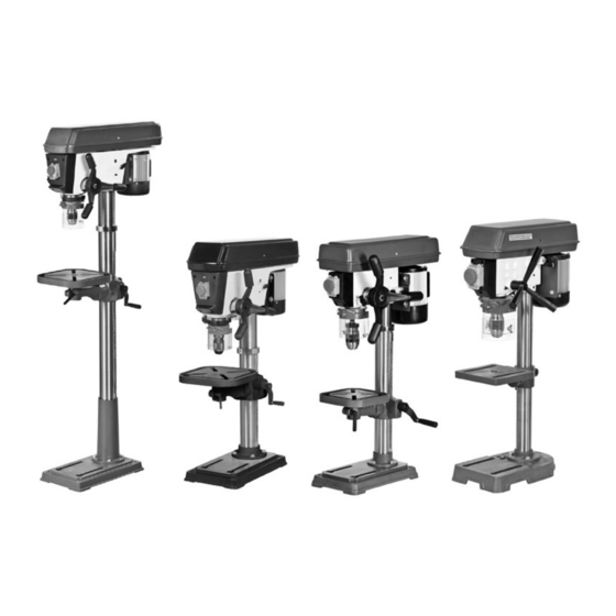
- Page 1 Code 505024 Code 700099 Code 700100 Code 700101 Pillar Drills Axminster Tool Centre, Unit 10 Weycroft Avenue, Axminster, Devon EX13 5PH axminster.co.uk...
-
Page 2: Declaration Of Conformity
Index of Contents Index of Contents Declaration of Conformaity What’s Included 03-04-05-06 General Safety Instructions General Safety Instructions for Drilling Machines 06-07 Specification Assembly 08-09-10-11-12-13 Illustration and Parts Description 14-15-16-17-18-19 Changing the Speed 20-21 Speed Select Table Removing the Chuck Assembly Maintenance Parts Breakdown/List 25-26-27-28-29-30... - Page 3 What’s Included Quantity Item Part Model Number 1 No ED16F2 Pillar Drill Code: 505024 ED16B2 Pillar Drill Code: 700100 ED16SB Pillar Drill Code: 700101 WD13L Pillar Drill Code: 700099 Box Containing: 1 No Pillar drill head 1 No Base 1 No Drill pillar complete with mounting flange, rise and fall rack and retaining ring 1 No...
- Page 4 What’s Included Guard shield and screws inside the pulley drive belt cover...
-
Page 5: General Safety Instructions
Having unpacked your machine and its accessories, please check the contents against the equipment General Safety Instructions list ”What’s Included” , if there are any discrepancies, please contact Axminster Tool Centre using the Work Place/Environment/Installation procedures laid down in the catalogue. Mains Powered Machines/ Primary Precautions... - Page 6 What’s Included Keep the machine clean; it will enable you to more Work Place/Environment easily see any damage that may have occurred. Do not use when or where it is liable to get wet. If the machine is to be used outside and it starts to rain Clean the machine with a damp soapy cloth if needs stop work and move it inside.
- Page 7 General Safety Instructions for Drilling Machines may have been used in setting up operations and put 11. It is not a good idea to wear gloves when them away in their correct stowage positions. operating a drill press. 7. Try to arrange the drilling operation so that the drill 12.
- Page 8 Assembly it to slide down the column until the rise and fall Assembly for ED16F2-ED16B2-ED16SB Pillar Drills rack is located in the cup chamfer in the top of the Please read through the section entitled mounting flange (see figs 9-10). Replace the cup...
- Page 9 Assembly Take the chuck guard and fit to the lower bearing Fig 04 flange of the quill mounting. Tighten the screw and nut fastening so that the drill guard is securely held in place (see fig 19). Fig 01 Worm drive shaft Machined flat Fig 05 Fig 02...
- Page 10 Assembly Cup chamfer Pinion Fig 11 Bristol clamping handle Rise and fall rack Fig 12 Fig 09-10 Bristol clamping handle Fig 13 Grub screw Grub screw...
- Page 11 Assembly Fig 14 Fig 17-18 WARNING! THE DRILLHEAD IS A HEAVY AND SUBSTANTIAL PIECE OF MACHINERY, YOU ARE ADVISED TO HAVE HELP TO LIFT IT CLEAR Phillips screw OF THE BOx AND FIT IT TO THE COLUMN. Fig 15 Raised boss Fig 19 Spigot Fig 16...
- Page 12 Assembly Fig 20 Table Locate the table/support assembly and slide it down the column until it rests on the base plate. Insert the bristol clamping handle into the threaded hole to Morse taper arbor the side of the table casting, slide the table up the column to working height and clamp the table in position, (see figs 23-24).
- Page 13 Assembly Fig 25-26 Fig 28 Guard moulding Guard shield Pillar drill head Pre-drilled hole WARNING! THE DRILLHEAD IS A HEAVY AND SUBSTANTIAL PIECE OF MACHINERY, YOU ARE ADVISED TO HAVE HELP! Using the 3mm Hex key loosen the two grub screws to the right side of the head, (see fig 29) lift the drill head above the column and let it drop into place.
- Page 14 Illustration and Parts Description Pillar Drills (ED16B2 and ED16F2) Pulley drive belt cover Motor yoke locking knob Light switch Motor On/Off switch shroud Lever Feed handle Chuck guard B16 Keyless Chuck Retaining collar Crank handle Drill table Rise and fall rack...
- Page 15 Illustration and Parts Description Pillar Drills (ED16B2 and ED16F2) Depth stop nuts On/Off switch (A) Motor yoke butterfly knob (A) Depth stop assembly (A) Emergency stop button (B) Drive belt tensioning lever lock (B) Depth stop scale (B) Pillar drill light switch...
- Page 16 Illustration and Parts Description Pulley drive belt cover Pillar Drill (ED16SB) Motor yoke locking knob On/Off switch shroud Motor Depth stop clamp Lever Feed handle Chuck guard Retaining collar B16 Keyless Chuck Drill table Crank handle Table clamping handle Rise and fall rack Drill column Mounting flange Base casting...
- Page 17 Illustration and Parts Description Pillar Drill (ED16SB) Motor yoke butterfly locking knob Drill table mounting Table clamping handle bracket clamping handle Table tilt clamping bolt On/Off switch (A) Table tilt pointer (A) Emergency stop button (B) Table tilt scale (B) Depth scale (A) Depth stop butterfly clamp Chuck guard...
- Page 18 Illustration and Parts Description Pillar Drill (WD13L) Pulley drive belt cover Motor yoke locking knob On/Off switch shroud Depth stop clamping nut Motor Chuck guard Lever Feed handle B16 Keyless Chuck Drill table Drill column Mounting flange Base casting 700099 (WD13L) Micro switch Quill pulley Motor pulley...
- Page 19 Illustration and Parts Description Pillar Drill (WD13L) Drill table mounting Motor yoke butterfly locking knob Depth stop clamping screw/nut bracket clamping handle Depth stop nuts Pointer Depth stop assembly (A) Chuck guard assembly Table tilt pointer (A) Depth stop scale (B) Table tilt scale (B)
-
Page 20: Changing The Speed
Turn clockwise to Fig 30 tension the belts Pillar Drills (ED16B2 and ED16F2) Only Locate and loosen the motor yoke butterfly locks (A). Locate the drive belt tensioning lever (B), (see fig 31) and turn it un-clockwise, to move the motor assembly “in”... - Page 21 Changing the Speed tensioning lever (B) clockwise, to move the motor Pillar Drill (WD13L) Only assembly “out” . Tighten the motor yoke butterfly knobs (A) to lock the motor assembly in position. To release the tention loosen the motor yoke tensioning lock which loosens the tension on the spring, push the motor up against the drillhead Pillar Drill (ED16SB) Only...
- Page 22 Speed Select Table 700100 (ED16B2)- 505024 (ED16F2) Pillar Drills 7000101 (ED16SB) Pillar Drill 700099 (WD13L) Pillar Drill...
- Page 23 Removing the Chuck Assembly Removing the chuck Preparation While holding the handle in place turn the chuck You wil require the morse taper drift (12) to line up the morse taper arbor (11) in the quills machined slot, (See fig 40). Insert the morse taper Pillar Drill (ED16SB) Only drift (12) in the quills slot, thus pushing the morse taper down and releasing the chuck, (See fig 41).
- Page 24 HAS BECOME DAMAGED If any servicing (other than the above cleaning) becomes necessary the unit should be returned to Axminster tool centre to be repaired by one of our qualified electrician. Contact our technical sales department for further assistance. Call 03332 406406 Email technical@axminster.co.uk...
- Page 25 Parts Breakdown/List Pillar Drills 505024 (ED16F) 700100 (ED16B2)
- Page 26 Parts Breakdown/List Pillar Drills 505024 (ED16F) 700100 (ED16B2) CENTER PULLEY BASE C-CLIP COLUMN SHOULDER SCREW RACK KNOB COLUMN WASHER HEX BOLT SPEED CHART LABEL SCREW SCREW MARK WASHER TABLE BRACKET HEX BOLT CLAMP BOLT SHIFTER WORM GEAR SET SCREW SHAFT...
- Page 27 Parts Breakdown/List Pillar Drill 700101 (ED16SB)
- Page 28 Parts Breakdown/List Pillar Drill 700101 (ED16SB)
- Page 29 Parts Breakdown/List Pillar Drill 700099 (WD13L)
- Page 30 Parts Breakdown/List Pillar Drill 700099 (WD13L)
- Page 31 Notes...
- Page 32 Please dispose of packaging for the product in a responsible manner. It is suitable for recycling. Help to protect the environment, take the packaging to the local recycling centre and place into the appropriate recycling bin. Only for EU countries Do not dispose of electric tools together with household waste material.
Need help?
Do you have a question about the Pillar Drills and is the answer not in the manual?
Questions and answers