Table of Contents
Advertisement
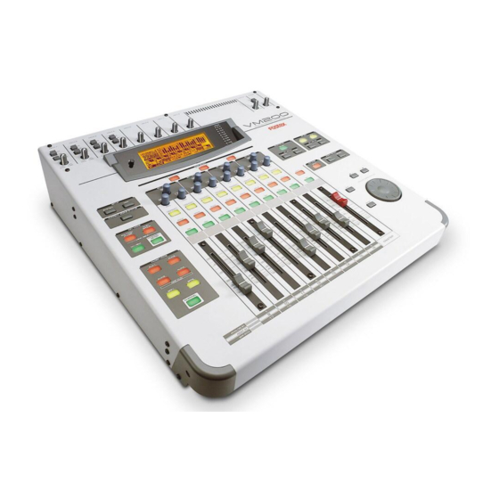
VM200
DIGITAL RECORDING MIXER
USER'S GUIDE
INPUT 1
INPUT 2
INPUT 3
INPUT 4
INPUT 5
INPUT 6
A
A
A
A
B
B
B
B
PAD
PAD
PAD
PAD
26dB
26dB
26dB
26dB
TRIM
TRIM
TRIM
TRIM
TRIM
TRIM
-16
-60
-16
-60
-16
-60
-16
-60
-10
-50
-10
+10
-34
+10
-34
+10
-34
+10
-34
1-8 ANALOG IN
SETUP
EQ/LO
EQ/LO-MID
SYSTEM
MIDI
GAIN
GAIN
FREQ
Q
FREQ
Q
CURRENT SCENE STATUS
PAN
PAN
PAN
PAN
EQ EDIT
EQ EDIT
EQ EDIT
EQ EDIT
KEY MODE
ROUTING/
PAIR/
PHASE
GROUP
SOLO
SOLO
SOLO
SOLO
MMC SEND
CHANNEL/
CH VIEW
METER
ON
ON
ON
ON
FADER MODE
AUX1
AUX2
AUX3
AUX4
+10
+10
+10
+10
ADD.AUX
0
0
0
0
EFF1
EFF2
-10
-10
-10
-10
CHANNEL
-20
-20
-20
-20
-30
-30
-30
-30
-40
-40
-40
-40
-
-
-
-
2
ANALOG IN
1
3
4
ADAT IN
9
10
11
12
EFF RTN
17
18
19
20
INPUT 7
INPUT 8
TRIM
TRIM
-50
-10
-50
-10
-50
MIN
METER
OL
-3
-6
VM200
-9
-12
-18
DIGITAL RECORDING MIXER
-24
-36
-48
L
R
ST BUSS/SOLO
PAGE SELECT
9-16 ADAT IN
17-20 EFF RTN
EQ/HI-MID
EQ/HI
SELECTED EQ
GAIN
GAIN
EQ ON
EQ LIBRARY
FREQ
Q
FREQ
Q
RECALL
STORE
PAN
PAN
PAN
PAN
EQ EDIT
EQ EDIT
EQ EDIT
EQ EDIT
REC BUSS
SOLO
SOLO
SOLO
SOLO
SOLO
SOLO
ON
ON
ON
ON
ON
EXIT
+10
+10
+10
+10
0
0
0
0
0
-10
-20
-10
-10
-10
-10
-30
ENTER
-20
-20
-20
-20
-40
-30
-30
-30
-30
-60
-40
-40
-40
-40
-
-
-
-
-
5
6
7
8
MASTER
13
14
15
16
MONITOR
PHONES
2TRK IN
GAIN
GAIN
MAX
MIN
MAX
EFF EDIT
EFF1
EFF2
EFF LIBRARY
RECALL
STORE
SCENE MEMORY
RECALL
STORE
/-1
+1/
DATA
Advertisement
Table of Contents

Related Manuals for Fostex VM200


Summary of Contents for Fostex VM200
- Page 1 VM200 DIGITAL RECORDING MIXER USER’S GUIDE INPUT 1 INPUT 2 INPUT 3 INPUT 4 INPUT 5 INPUT 6 INPUT 7 INPUT 8 26dB 26dB 26dB 26dB TRIM TRIM TRIM TRIM TRIM TRIM TRIM TRIM PAGE SELECT 1-8 ANALOG IN 9-16 ADAT IN...
-
Page 2: Safety Instructions
CAUTION RISK OF ELECTRIC SHOCK DO NOT OPEN CAUTION: TO REDUCE THE RISK OF ELECTRIC SHOCK, DO NOT REMOVE COVER (OR BACK). NO USER - SERVICEABLE PARTS INSIDE. REFER SERVICING TO QUALIFIED SERVICE PERSONNEL. "WARNING" "TO REDUCE THE RISK OF FIRE OR ELECTRIC SHOCK, DO NOT EXPOSE THIS APPLIANCE TO RAIN OR MOISTURE."... -
Page 3: Table Of Contents
Chapter Contents ......9 Welcome to the VM200 ......10 Using this Guide . - Page 4 Chapter Contents ......43 VM200 System Example..... . . 44 Connecting the Power Cord .
- Page 5 Chapter Contents ......123 VM200 Effects......124...
- Page 6 Assigning S/P DIF Signals to Channels ..169 Cascading the VM200 ..... . . 171...
- Page 7 VM200 & MIDI ......173 CHAPTER 11 Initializing the VM200 ....197 CHAPTER 12 Specifications and Data .
- Page 8 VM200 User’s Guide...
-
Page 9: Chapter 1 Introducing The Vm200
Chapter Contents Welcome to the VM200 ......10 Using this Guide....... . . 10 Installing the VM200 . -
Page 10: Welcome To The Vm200
Chapter 3: Getting Started offers illustrated system examples and explains how to connect and turn on the power to the VM200, and try out a few features, such as the EQ and Effects processors. Chapter 4: Inputs describes the available input channels and dis- cusses pad switches, trim controls, phase inversion, as well as mut- ing, panning, grouping, and routing input channels. -
Page 11: Installing The Vm200
Installing the VM200 Locate the VM200 on a level, stable surface. You can also mount the VM200 vertically in a rack using the Fostex 9910 optional rack mount adapter. Remove the six screws from the bottom of the VM200, attach the rack mount adapter, then reinstall the screws as shown in the illustration below. -
Page 12: Feature Summary
Introducing the VM200 Feature Summary This section summarizes the main features of the VM200. Audio Specifications 20-bit 64-times oversampling, delta sigma modulation A/D con- verters 20-bit 128-times oversampling, delta sigma modulation D/A con- verters 90dB or higher dynamic range 20Hz to 20kHz, +1dB/-3dB frequency response industry standard 44.1K or 48K sampling rates... -
Page 13: Midi Functions
(Presets and User tables) You can use System Exclusive messages to control mixer parame- ters You can output MIDI Machine Code (MMC) by pressing keys on the control panel MIDI Bulk Dump capability for data backup and transfer VM200 User’s Guide Mixer Functions... -
Page 14: Why A Digital Mixer
Introducing the VM200 Mixer Configuration The VM200 is equipped with a total of 20 analog and digital inputs: eight analog mono input channels (1-8), four internal effects returns, and an eight-channel ADAT digital input. A two-channel S/P DIF digital input signal can be routed to any of 20 channels, and a two-track analog input (2TRK IN) is also provided. -
Page 15: Dual On-Board Effects Processors
Digital I/O The VM200 features two types of digital inputs and outputs: S/P DIF and ADAT. The S/P DIF is a two-channel digital I/O commonly found on con- sumer CD players, computer audio cards, etc. -
Page 16: Midi
“scene,” in the Scene Memory. The Scene Memory can store up to 100 scenes, which you can later recall by simply pressing a key on the VM200, or by issuing a remote MIDI Program Change command from a connected MIDI device. -
Page 17: Chapter 2 Touring The Vm200
Touring the VM200 CHAPTER 2 About This Chapter This chapter takes you on a guided tour of the VM200, introducing various components of the control surface, including the faders, rotary controls, the Data Wheel, and other features. It also explains the operations associated with each function key. -
Page 18: Top Panel Control Surface
Touring the VM200 Top Panel Control Surface The following illustration shows the top panel control surface of the VM200. Each section of the mixer is discussed in the following pages. INPUT 1 INPUT 2 INPUT 3 INPUT 4 26dB 26dB... -
Page 19: Analog Control Section
TRIM TRIM A/B Input selectors The VM200 features four A/B Input selectors that enable you to select the A or B inputs for input channels 1 through 4. The A Inputs are balanced XLR-type connectors for use with micro- phones that feature XLR-type plugs, such as condenser microphones, or other input devices that require XLR connectors. -
Page 20: Lcd Display
Touring the VM200 Monitor Gain knob Use the Monitor Gain knob to adjust the Monitor Out level. The Monitor Out jacks output the buss signal you specify on the SETUP SYSTEM 1:CLOCK/MON OUT.) Phones Gain knob Use the Phones Gain knob to adjust the headphone output level. -
Page 21: Data Wheel And Neighboring Keys
Data Wheel and Neighboring Keys The Data Wheel is located in the lower-right corner of the VM200. It enables you to scroll through lists of programs in the Effect and EQ Libraries. You can also use the Data Wheel to move the cursor left and right when naming a new effect or EQ program. -
Page 22: Function Keys
Touring the VM200 Function Keys This section provides a brief tour of the VM200’s numerous function keys. When you press certain function keys, such as , the VM200 displays a “function page” of information SCENE STATUS] on the LCD Display Panel. Each function page contains parameters that you can set to configure and control the VM200. -
Page 23: Setup Section
3:CH RCL SAFE 4:SOLO SAFE 5:POWER ON RCL 6:INITIALIZE [MIDI] Key key enables you to interface the VM200 with MIDI (Musical [MIDI] Instrument Digital Interface) instruments and devices. key also features six function pages, as summarized below: [MIDI] MIDI Key Function Pages 1:MIDI TX&RX... -
Page 24: Current Scene Status
Press a Page Select key to specify Channels 1-8, 9-16, or 17-20. Then press the [EQ EDIT] [SOLO] the signal to a potential destination. The indicator in the chan- nel/buss matrix highlights (dark square). key, the VM200 enters CURRENT SCENE STATUS function page enables you to: , and [CH VIEW] [CHANNEL/METER]... -
Page 25: [Pair/Group] Key
EQ settings from a source channel to destina- tion channels. CH VIEW specific channels. VM200 User’s Guide function page lets you invert the phase for each of input [ROUTING/PHASE] key to enter MMC mode. (For more information, see Includes parameters that enable you to... -
Page 26: [Channel/Meter] Key
[CHANNEL/METER] tion pages: Channel Edit/Input and Channel Edit/Output. These are essentially the “main” pages of the VM200, the pages you will likely display most often. However, unlike other function pages, the name of the page does not appear on a page. -
Page 27: Fader Mode Section
EFF1 CHANNEL The VM200 features 20 input channels and 18 output channels. However, with only eight faders plus the Master fader, the VM200 must use its faders for multiple tasks to accommodate all those channels. Depending on the Fader Mode, the faders (as well as the [EQ EDIT] functions the faders and keys will control by selecting a Fader Mode. -
Page 28: Selected Eq Section
Selected EQ Section An equalizer (EQ) enables you to boost or cut specific frequency ranges to “shape” a sound. The VM200 features a four-band parametric equalizer for each input channel. Each band features rotary controls for Gain, Frequency, and Q. -
Page 29: Eff Edit Section
The Effect Library stores effects that you can recall. It features 50 preset effects and effect combinations. You can modify the parameters for these existing effects to create and store an addi- tional 50 custom effect programs. VM200 User’s Guide key displays the EQ LIBRARY STORE [STORE]... -
Page 30: [Recall] Key
For more information, see “Effects” on page 123. Rec Buss Section The Rec Buss section features only the The VM200 also features ter fader. For more information on the Rec Buss “Soloing the REC BUSS OUT” on page 113. The REC BUSS is enabled only when the ADD. AUX parameter is turned off. -
Page 31: Scene Memory Section
A “scene” is a collection or “snapshot” of virtually all the parameter settings of the VM200 at a given point in time. [RECALL] Key Pressing the page. -
Page 32: Channel Control Section
Channel Control Section EQ/LO GAIN FREQ EQ EDIT EQ EDIT SOLO SOLO Faders The VM200 features nine 60mm motorized faders. Faders 1 through 8 are associated with separate , and [ON] [SOLO] [EQ EDIT] (The Master fader features only keys.) - Page 33 1–8 (ANALOG IN) | 9–16 (ADAT IN) | 17–20 (EFF RTN) CHANNEL AUX1 AUX2 AUX3 AUX4 EFF1 EFF2 VM200 User’s Guide Input Channel Channel Gain Channel to AUX1 Send Gain Channel to AUX2 Send Gain Channel to AUX3 Send Gain Channel to AUX4 Send Gain Channel to EFF1 Send Gain...
-
Page 34: [On] Keys
AUX1 AUX2 AUX3 Channel ON/OFF AUX4 EFF1 EFF2 [ON], [SOLO], & [EQ EDIT] Keys The VM200 features eight sets of , and keys, one set for each [SOLO] [EQ EDIT] channel fader. The Master fader also features a and an key. - Page 35 AUX1 AUX2 AUX3 AUX4 EFF1 EFF2 VM200 User’s Guide keys enable you to solo channels for monitoring. SETUP:SYSTEM 1:CLOCK/MON keys solo channels 1-20, depend- [SOLO] keys control various functions depending on the current key solos the AUX1 Buss. In Fader...
-
Page 36: Eq Section Rotary Controls
Channels 1–8 is Channels 9–16 is turned OFF.) EFF1 EFF2 EQ Section Rotary Controls The VM200 EQ section is horizontally subdivided into four sections: EQ-LO, EQ/LO-MID, EQ/HI-MID, and EQ HI. EQ/LO GAIN FREQ FREQ Each band features three knobs labelled Gain, Freq, and Q that con- trol the parametric equalizer in EQ Edit mode. - Page 37 Page Select Keys The VM200 uses a channel-layer format, in which its nine faders per- form multiple tasks to accommodate 20 input channels. You can imagine the VM200 as being divided into three layers. Layer 1 provides access to Channels 1 through 8, which primarily handle the analog inputs.
-
Page 38: Rear Panel
Touring the VM200 Rear Panel All inputs and outputs on the VM200 are conveniently located on the rear panel. The following paragraphs briefly describe each input and output. PHONES MONITOR OUT 2TRK IN ST BUSS OUT REC BUSS OUT ADD.AUX SEND... - Page 39 You can connect an external effects unit to these connectors using an insert cable to send the signal to the effects unit and return it to the VM200. (For more information, see “Insert Channels 1–4” on page 62.) The Insert connectors allow you to insert a signal into the signal chain after the PAD switches and TRIM knobs.
- Page 40 MIDI messages received by the MIDI IN port. 75 On, Off Switch This switch turns WORD IN termination on and off. If the VM200 is the last device to receive word clock via the WORD IN connection, turn this termination switch on.
-
Page 41: Block Diagram
Block Diagram Block Diagram VM200 User’s Guide... - Page 42 Touring the VM200 VM200 User’s Guide...
-
Page 43: Chapter 3 Getting Started
9 and “Touring the VM200” on page 17 before you “get started.” Chapter Contents VM200 System Example ......44 Connecting the Power Cord Turning the VM200 On and Off . -
Page 44: Vm200 System Example
Getting Started VM200 System Example The following illustration shows one example of a recording studio based on the VM200. Guitar processor Lead guitar Guitar processor Second guitar Bass processor Bass guitar MIDI keyboard MIDI Interface ADAT compatible Master recorder ANALOG IN... -
Page 45: Connecting The Power Cord
Use the included power cord to connect the VM200 to an appropriate AC electrical outlet. Insert the female end into the AC input on the rear panel of the VM200. Insert the male end into a wall outlet of an appropriate voltage for your area. -
Page 46: A Few Tips On Using The Vm200
This type of design can work well, but is redundant and subject to analog noise. The VM200 is a digital recording mixer, and does not conform to ana- log recording conventions. The VM200 uses an innovative “channel layering” system that enables you to control up to 20 channels using only eight faders and one Master Fader. - Page 47 The [1–8 ANALOG IN] key is lit. You can control channels 1–8. The [9–16 ADAT IN] key is lit. You can control channels 9–16. The [17–20 EFF RTN] key is lit. You can control channels 17–20. VM200 User’s Guide Channel Layers...
-
Page 48: An Important Note About Word Clock Information
final recording. With the VM200, you can record and mixdown entirely in the digital domain. This may make a dramatic improvement in the quality of your final recordings. -
Page 49: Reading The Display
Lower and Raise Faders to Initiate Sends If on occasion you think you have configured the VM200 to send a particular signal to a buss, but you unexpectedly cannot hear the output, try bringing the fader down and raising it back up to the desired level to initiate the send. -
Page 50: Function Page Parameter Matrix
On such a function page, the four Gain rotary controls adjust param- eters in the top row, and the Freq and Q rotary controls adjust the parameters in the bottom row. , and keys to toggle two-state indi- [SOLO] [ON] Level indicator VM200 User’s Guide... -
Page 51: Lit & Flashing Led Keys
CH FADER parameter on and off. Lit & Flashing LED Keys Many of the keys on the control surface of the VM200 are translu- cent and fixed in position over an LED light that can provide status information. -
Page 52: Finally
Finally...Let’s Get Started! The following procedure lets you try out some of the capabilities of your VM200. To simplify the explanation, in this procedure we will connect a microphone to channel 1, adjust the EQ, apply effects, and record the signal. -
Page 53: Powering On
If you just want to try out the EQ and some effects, you can skip this step (step 3) altogether. Lower all faders and Gain and Trim knobs on the VM200. Powering On Press the Power button on the rear panel to turn on the power to the VM200. - Page 54 For example, watch the response curve swell as you raise the EQ/HI-MID Gain, as illustrated in figures A and B below. key. [EQ EDIT] [EQ ON] the response curve swells when Gain is raised key in the VM200 User’s Guide...
- Page 55 EQ/HI-MID Q value is raised. You can store EQ settings in a program, or you can recall a preset EQ program. Refer to “EQ” on page 75 for more information. VM200 User’s Guide Adjusting the EQ...
- Page 56 Let’s apply some effects from the Eff2 effect processor to the signal. Press the key in the Eff Edit section. [EFF2] The [EFF2] key lights up orange and the VM200 displays the EFF EDIT function page. Press the [RECALL] The VM200 displays the following EFFECT LIBRARY RECALL function...
-
Page 57: Recording
REC and PLAY button on the recorder to begin recording. You can now record your performance to the recorder. To check the input and output levels of the VM200, press the [CHANNEL/METER] key to toggle between the input and output meters. - Page 58 Getting Started VM200 User’s Guide...
-
Page 59: Chapter 4 Input Channels
Input Channels CHAPTER 4 About This Chapter This chapter provides an overview of the VM200’s input channels, including phantom power, routing, pairing, grouping, copying channel settings, and more. Chapter Contents Input Channels 1–4 ......60 Input Channels 5–8 . -
Page 60: Input Channels 1-4
Turn off the corresponding phantom power switch before you connect a dynamic microphone; otherwise, you may damage the microphone. If you turn on the power to the VM200 while the input channel’s phantom power switch is turned on, the VM200 displays a warning message: “Warning! +48V SW ON!”... -
Page 61: Input Channels 5-8
Phantom Power for Input Channels 1–4 The VM200 supplies optional phantom power (+48 V) to the XLR con- nectors. You can turn the phantom power on or off using the switches on the rear panel as shown in the figure above. -
Page 62: Insert Channels 1-4
Input Channels Insert Channels 1–4 You can use a Y-shaped insert cable to connect the VM200 to an external effects processor. The signal flows out of the VM200 Insert connector, into and out of the effects processor, and back into the VM200 via the insert cable. -
Page 63: Pad Switches (Input Channels 1-4)
VM200 UserÕs Guide 26dB 26dB 26dB INPUT 3 INPUT 4 INPUT 5 26dB 26dB 26dB TRIM TRIM TRIM Pad Switches (Input channels 1–4) INPUT 6 INPUT 7 INPUT 8 TRIM TRIM TRIM VM200 uses “boxed” values when Pad switch is depressed. -
Page 64: Inverting The Input Phase
Phase is often represented by this symbol: On the VM200, you can invert the phase for channels 1–20. First you access the PHASE function page, then press an phase inversion on or off. A light indicator on the display means phase is normal (off) for that channel;... -
Page 65: Input Channel Eq
If it is not already selected, select the desired channel layer using a Page Select key, then press the channel’s The VM200 features seven Fader Modes. The faders control different functions and parameters depending on the current Fader Mode. You can select a Fader Mode by pressing one of the keys in the Fader Mode section, such as page 32 for more information about Fader Modes.) -
Page 66: Routing Input Channels
Input Channels The VM200 displays the CHANNEL EDIT function page. panpot icon Use the Page Select keys to select the target channel layer. Use the panpot rotary controls to make the pan settings. The display shows a dial icon for each channel that visually indi- cates the pan position. -
Page 67: Monitoring And Soloing Input Channels
Aux 3 and 4 when ADD. AUX mode is turned on.) You can also configure input channel sends as either pre-fader or post-fader. See “Using the AUX Sends” on page 115 for more information. VM200 User’s Guide Monitoring and Soloing Input Channels , or... -
Page 68: Pairing Channels
For example, you may wish to turn all the channels devoted to a cho- keys, faders, Aux sends, Effect sends, key to display the 1:CH PAIR function key for one of the channels you wish to key to cancel any stereo [EQ EDIT] [CHANNEL/METER] key to return to key. [ON] VM200 User’s Guide... -
Page 69: Grouping Faders
Three groups are available: Mute Groups A, B, and C. Press the GROUP function page. VM200 User’s Guide key twice to display the 2:MUTE GROUP [PAIR/GROUP] key and all [EQ EDIT], [SOLO], and [ON] keys... -
Page 70: Viewing Input Channel Settings
The CHANNEL VIEW function page enables you to view the settings for any input channel. You cannot adjust any parameters on the CHANNEL VIEW function page. (If you try to adjust the pan setting, the VM200 displays the CHANNEL EDIT function page.) Press the... - Page 71 [ON] key status Press the Channel Edit mode. VM200 UserÕs Guide key for the target channel. [EQ EDIT] key lights up. The number of the selected [EQ EDIT] routing (Direct, Rec buss, St buss)
-
Page 72: Copying Channel Settings
(from start of cycle) to display keys for all channels flash. The [EQ EDIT] key for the copy source channel. key lights up. The CHANNEL COPY function page key of the copy destination [EQ EDIT] VM200 User’s Guide... - Page 73 (enables) the selected destination channel(s) as fol- lows. Press the The CHANNEL COPY function page flashes the word “COMPLETE!” on the display for a few seconds, and the VM200 displays the first CH COPY function page. Press the Channel Edit mode.
- Page 74 Input Channels VM200 User’s Guide...
-
Page 75: Chapter 5 Eq
CHAPTER 5 About This Chapter This chapter explains how to use the VM200 four-band parametric equalizer (EQ) and how to edit, recall, and store EQ settings. Chapter Contents Equalizers (EQ)........76 Adjusting the EQ . -
Page 76: Equalizers (Eq)
Equalizers (EQ) The VM200 features a four-band parametric equalizer for input channels 1–16. The four-band equalizer subdivides the audio spectrum into LO, LO-MID, HI-MID, and HI frequency ranges. Each of the four bands includes rotary controls for Gain, Frequency, and Q. -
Page 77: Adjusting The Eq
You can adjust the EQ for each of the four bands using three rotary controls: Gain, Freq, and Q. These three EQ controls form a triangu- lar shape on the top panel of the VM200. The LCD display also features four sets of three circular knob icons. - Page 78 Press the key in the Selected EQ section to turn it on. [EQ ON] key lights up, and the VM200 turns on the EQ for the [EQ ON] selected channel. The EQ On/Off indicator in the lower-right corner of the display shows “On”...
- Page 79 If you select HPF or LPF for LO band Q or HI band Q respectively, the Gain rotary control for LO EQ or HI EQ functions as the On/Off switch. The following table shows the VM200 EQ specifications. Gain (G) Frequency (F) 1.
-
Page 80: Eq Enabling Channels
The selected [EQ EDIT] EQ EDIT function page. Press the key in the Selected EQ section. [EQ ON] key lights up, and the VM200 turns on the EQ for the [EQ ON] selected channel. key. [CHANNEL/METER] key), press the [EQ ON] Page Select key to [9–16 ADAT IN]... -
Page 81: Resetting The Eq
The following confirmation dialog appears on the display. Press the cancel the reset operation. VM200 User’s Guide key turns off (goes dark), and the VM200 turns off the EQ On/Off indicator. Here, EQ is bypassed. Lo-Mid 0 dB 0 dB... - Page 82 If you have pressed the channel will be reset to the initial values. Press the key or the [EXIT] Channel Edit mode. key, all EQ parameters for the [ENTER] key to return to [CHANNEL/METER] VM200 User’s Guide...
-
Page 83: Eq Library
Deep_SD Talk_Tom Melo.Tom W.GongTom Brill.Cym Lo-Fi_Cym Vivid_HH Sharp_HH Lo-Fi_HH Perc. Tamb. Fat_Bass Norm.Bass Loud_Bass PowerBass Bright_Pf Loud_Pf Power_Pf VM200 User’s Guide EQ Library Name Real_Pf E.Pf Clean_EG Crunch_EG OverDrvEG Dist.EG Metal_EG Stroke_AG StrokeEAG Arpeg.GG Arpeg.EAG Arpeg.AG Brass_Sec W.WingSec Male_Vo1 Male_Vo2... -
Page 84: Recalling Eq Programs
[EQ EDIT] recall an EQ setting. The selected [EQ EDIT] The VM200 displays the EQ EDIT function page, which shows the parameter settings for the selected channel. Press the Selected EQ Press the EQ Library The VM200 displays the EQ LIBRARY RECALL function page. The key for the selected channel flashes. - Page 85 Steps 2 EDIT] through 5. Press the page and return to the CHANNEL EDIT function page. VM200 User’s Guide key at any time to exit the EQ Library Recall [EXIT] Recalling EQ Programs...
-
Page 86: Storing Eq Programs
“(No Data)”. Press the key. [ENTER] The VM200 displays the EQ LIBRARY NAME EDIT function page. character-selector cursor The EQ LIBRARY NAME EDIT function page includes a character selec- tor box that displays all the letters of the alphabet, as well as numerals and punctuation symbols. - Page 87 EQ program. The following warning dialog appears for a brief moment, followed by the EQ EDIT function page. Warning: Do not power off the VM200 while it is writing to memory or you may damage the system. Press the LIBRARY NAME EDIT function pages.
-
Page 88: Editing Eq Program Titles
You cannot change the names of Preset programs 00–49. Press the key to recall the desired EQ Program. [ENTER] The VM200 displays the EQ EDIT function page, which shows the recalled EQ parameter values applied to the current channel. Press the EQ Library STORE function page. - Page 89 When you’ve finished re-naming the program, press the [ENTER] The VM200 displays the EQ EDIT function page. WARNING: Do not power off the VM200 while it is writing to memory or you may damage the system. Press the EQ LIBRARY NAME EDIT function pages.
-
Page 90: Copying Eq Settings
(disabled) as a copy des- tination. Press the [CH VIEW] The VM200 displays the 3:EQ COPY function page. key and the [CH VIEW] selected Page Select key lights up; unselected Page Select keys flash. - Page 91 (enables) the selected destination channel(s) as follows. source channel Press the The EQ COPY function page flashes the word “COMPLETE!” on the display for a few seconds, and the VM200 displays the first CH COPY function page. Press the Channel Edit mode.
-
Page 92: Eq Preset Library Parameters
.125 3.78K 8.00K sound. -6.0 -1.0 +7.0 Creates a “sparkling” 55.7 1.94K 5.66K and brilliant cymbal sound. +2.5 -4.0 -&.0 Emphasizes the mid to low range to muffle 40.5 3.27K 4.00K “sparkling” part of cym- bals. Description VM200 User’s Guide... - Page 93 13 Vivid_HH 14 Sharp_HH 15 Lo-Fi_HH 16 Perc. 17 Tamb. 18 Fat_Bass 19 Norm.Bass 20 Loud_Bass 21 PowerBass 22 Bright_Pf 23 Loud_Pf 24 Power_Pf 25 Real_Pf VM200 User’s Guide Parameter Lo-Mid Hi-Mid Gain -7.5 -2.5 +4.0 Freq. 93.6 2.31K 0.79 Gain -9.0...
- Page 94 Adjusts the balance of -2.5 +2.0 +4.0 brass section sound 96.4 2.52K 5.66K (such as trumpets and 0.79 trombones). Emphasizes the rich +3.0 +4.0 mid-range of wind 3.38K 8.00K instruments, such as clarinets and oboes. Description VM200 User’s Guide...
- Page 95 Name 39 Male_Vo1 40 Male_Vo2 41 FemaleVo1 42 FemaleVo2 43 Chorus 44 Speech_1 45 Speech_2 46 Digi.Mix 47 AnalogMix 48 Telephone 49 Husky VM200 User’s Guide Parameter Lo-Mid Hi-Mid Gain -1.0 +2.0 Freq. 1.00K 2.00K 0.56 Gain +2.5 -4.0 -2.0 Freq.
- Page 96 VM200 User’s Guide...
-
Page 97: Chapter 6 Monitoring Signals
Monitoring Signals CHAPTER 6 About This Chapter This chapter explains how to monitor signals on the VM200, includ- ing selecting a monitor output, soloing, using the two-track input, as well as viewing meters and send levels. Chapter Contents Monitoring and Soloing ......98 MON SEL Parameter. -
Page 98: Monitoring And Soloing
[SOLO] The Setup:System 1:CLOCK/MON function page features two parameters that control the monitoring and soloing functions of the VM200: the MON SEL (monitor select) and SOLO MODE parameters. You can display the 1:CLOCK/MON function page by pressing the key. -
Page 99: Monitor Outs And Phones
2TRK IN jacks for confidence monitoring or master play- back. The 2TRK IN accepts phono jacks with a –10 dBV nominal input level. 2TRK IN switch VM200 User’s Guide key for the desired channel. [SOLO] MONITOR PHONES... -
Page 100: Monitoring
EFF2 Effect processor EFF2 AUX1&2 Auxiliary 1 and Auxiliary 2 mixed AUX3&4 Auxiliary 3 and Auxiliary 4 mixed Press the [CHANNEL/METER] The VM200 exits Setup mode and displays the CHANNEL EDIT func- tion page. key. EQ/LO-MID EQ/HI-MID GAIN GAIN FREQ FREQ key. -
Page 101: Soloing
Set the Monitor Gain control to about halfway. (If you are using headphones, set the Phones Gain control to about halfway.) Press the Setup The VM200 displays the 1:CLOCK/MON function page. Rotate the channel 5/6 (EQ/HI-MID) Gain rotary control to select the desired Solo Mode. EQ/LO... - Page 102 Monitoring Signals PFL: In PFL (Pre-Fader Listen) mode, the VM200 feeds a soloed channel’s pre-fader signal to the Solo buss and then outputs it only to the MONITOR OUT and PHONES. Pressing the appropriate master or Rec Buss signal before it is adjusted by the Master Fader or Rec Buss Gain parameter.
- Page 103 68), their [SOLO] keys are linked. Note: If Solo Mode is set to M-SOLO, you must raise the fader for the soloed channel and the Master fader or you will not hear any output. VM200 User’s Guide key for the channel(s) you [SOLO] keys light up.
- Page 104 Monitoring Signals Solo Safe Function The VM200 features a Solo Safe function that enables you to desig- nate specific channels as “solo safe.” You can monitor solo safe channel signals that are sent to the stereo buss regardless of the channel’s available when Solo Mode is set to M-Solo (see page 98).
-
Page 105: Metering Signal Levels
If this happens, lower the levels. Otherwise the signal may distort. Viewing Input/Output Level Meters Press the modes). The VM200 displays the first CHANNEL EDIT page, which features input level meters. Press the between the input level meters and output level meters. VM200 User’s Guide... -
Page 106: Viewing Channel, Aux Send & Effect Send Meters
Monitoring Signals LED Display Meter (L/R or ST BUSS/SOLO) The VM200 features two LED meters to the right of the LCD Display that enable you to view stereo output levels. These nine-segment LED meters display levels for the left and right channels (L/R) or the Stereo Buss and soloing channels (St Buss/Solo). -
Page 107: Chapter 7 Outputs
Outputs CHAPTER 7 About This Chapter This chapter describes the output configurations of the VM200, including the stereo buss output, the recording buss output, the ADAT and S/P DIF digital outputs, and the auxiliary (AUX) sends. Chapter Contents Overview........108 ST BUSS OUT. -
Page 108: Overview
“Effects” chapter page 123. ST BUSS OUT The VM200 converts the digital stereo buss (ST BUSS) signal to an analog signal using 20-bit 128-times oversampling D/A converters. It then outputs it from the ST BUSS OUT unbalanced phone jack (located on the rear panel) with a –10 dB nominal output level. -
Page 109: Adat Out & S/P Dif Out
DIF OUT connectors. You can connect any ADAT-compatible recording device to the ADAT OUT optical connector, including a Fostex VR800 recorder, Alesis® ADAT, Alesis ADAT-XT, or other digital multitrack recorders. The S/P DIF OUT uses an optical connector. You can use this to route the stereo signal to any S/P DIF format audio device, such as a com- puter soundcard or DAT recorder. -
Page 110: Using The St Buss Out
Outputs Using the ST BUSS OUT The VM200 converts the ST BUSS stereo digital signal to analog using 20-bit 128-times oversampling D/A converters. The analog sig- nal is then output from the ST BUSS OUT connectors on the rear panel. These connectors are unbalanced phone jacks with a –10 dB nominal output level. -
Page 111: Setting The St Buss Out Level
Fader Mode, you may need to press [CHANNEL] you can mute the stereo buss output. This places the VM200 in Channel Fader Mode, enabling the Master key to mute the stereo output. [ON] See “[ON] Keys” on page 34 for more information. -
Page 112: Using The Rec Buss Out
Outputs Using the REC BUSS OUT The VM200 converts the REC BUSS stereo signal to analog using 20-bit 128-times oversampling D/A converters. The analog signal is then output from the REC BUSS OUT connectors on the rear panel. These connectors are unbalanced phone jacks with a –10 dB nominal output level. -
Page 113: Setting The Rec Buss Out Level
You can set the Rec Buss output level on the CURRENT SCENE STATUS function page. Press the The VM200 displays the CURRENT SCENE STATUS function page. Rotate the EQ/HI Gain rotary control (channels 7/8) to adjust the REC-B GAIN parameter. - Page 114 FREQ Note: If you try to operate the Gain rotary control while the ADD.AUX parameter is turned ON, the VM200 displays a warning message and you will be unable to adjust the REC-B Gain. Use the EQ/LO-MID Gain rotary control (channels 3/4) to turn off the ADD.AUX parameter on the CURRENT SCENE STATUS function page.
-
Page 115: Using The Aux Sends
Using the AUX Sends The VM200 features four auxiliary (AUX) sends, which enable you to send a signals to various destinations. You can send signals from input channels 1 through 20 to AUX Sends 1 through 4. You can use the four AUX Sends individually or in stereo pairs. -
Page 116: Monitoring Aux Sends
You can display the CHANNEL EDIT/OUTPUTS function page to view the AUX Send master level by pressing the See “Monitoring Signals” on page 97 for more information. key to display the [CH VIEW] key for the Aux Send channel. [EQ EDIT] [CHANNEL/METER] key twice. VM200 UserÕs Guide... -
Page 117: Pre-Fader/Post-Fader Aux Sends
Follow these steps to configure each AUX Send as pre-fader or post-fader. Press the The VM200 displays the CURRENT SCENE STATUS function page. VM200 User’s Guide Sending Channel Signals to AUX Sends button, and then raising the fader. [CHANNEL]... -
Page 118: Muting Aux Sends
Stereo Buss and Effects , or key to select an AUX Send [AUX4] , or key to select an AUX [AUX4] button to turn the AUX Send on and off. [ON] buttons [ON] VM200 UserÕs Guide... -
Page 119: Pairing Aux Sends
Send are set the same and linked for simultaneous control. Follow these steps to pair AUX Sends: Press the The VM200 displays the CURRENT SCENE STATUS function page. Use the Freq and Q rotary controls for channels 7/8 to turn the A1&A2 and A3&4 parameters On or Off. -
Page 120: Smoothing Function
Depending on the sound you are mixing, you may hear a slight step- ping noise when you slide the faders. This indicates an overloaded CPU. To resolve this problem, the VM200 features a Smoothing func- tion that reduces CPU load to achieve smoother fader adjustment. -
Page 121: Viewing Buss Routing For Each Channel
Stereo Buss, or the Record Buss. Press the Press the The VM200 displays the 1:CH VIEW function page, which includes the ROUT indicator in the top center of the display. The D, R, and S indicators represent the ADAT Direct Outs, the Record Buss, and the Stereo Buss. - Page 122 Outputs VM200 User’s Guide...
-
Page 123: Chapter 8 Effects
Chapter Contents VM200 Effects ....... . . 124 Effects Library ....... . . 125 Effect Preset Library List. -
Page 124: Vm200 Effects
(Hi-Density Logarithmic Processing), which eliminates the mutual interference between the numerous integrated delay modules and reduces sonic impurities and “grit.” The VM200 includes an Effects Library that contains 50 Preset pro- grams and 50 User programs. See the “Effects Library” on page 125 for more information. -
Page 125: Effects Library
Effects Library The VM200 also includes an Effects Library that contains 50 Preset programs and 50 User programs. Effect Preset Library List The following table lists the Preset effect programs. See “Effects Parameters” on page 139 for detailed parameter information. - Page 126 3-tap delay, which can create interesting effects with your wizardry. Description Standard chorus effect setting. More natural and spacious effects than Chorus. Standard flanging effect setting. You can pan two types of effects sound to any position. VM200 User’s Guide...
- Page 127 -Normal Hall Panning Delay -Normal Plate CHORUS- REVERB REVERB- CHORUS FLANGE- REVERB REVERB -FLANGE VM200 User’s Guide Display Description MonoPITCH Standard pitch shifter. Stereo pitch shift with two channels pitch-shifted DualPITCH independently. Display Description MnDL-NmHL Combination of mono delay and hall reverb.
-
Page 128: Applying Effects
Press the [EFF1] an effects processor. The selected key lights up and the VM200 displays the EFF EDIT function page, which includes parameters for the current effect. Recall the desired effects program from the Effects Library. (For more information on how to recall the effects program, see “Recalling Effects Programs”... -
Page 129: Sending Signal To Effects Processor
66 for more information. You can also route signals to AUX Sends 1 through 4. (Note that the REC BUSS OUT is disabled if AUX Sends 3 and 4 are selected). VM200 User’s Guide key is turned on. [ON] Page Select key. -
Page 130: Controlling The Sends Signals
[EXIT] Viewing and Adjusting the Effect Send Level The VM200 enables you to view and adjust effect send levels for effects processors EFF1 and EFF2 on the Channel View (CH VIEW) function page. A graphic image of a fader and a numerical value rep- resent the send levels on the display. -
Page 131: Viewing And Adjusting The Effect Send Master Level
Page Select key and [EQ EDIT] The VM200 displays a new channel number in the CH section, near the upper-left corner of the display. Press the EFF1 or EFF2 key in the Fader Mode section to specify an effects processor. -
Page 132: Monitoring Effects Sends
AUX buss outs. See “Panning Input Channels” on page 65 for more information. key in the Fader Mode section to [EFF2] key to turn the Effect Send on or off. [ON] key in the Fader Mode section. Page Select key. effect return level key. The [ON] VM200 UserÕs Guide... -
Page 133: Effects Library
Effects Library The VM200 stores effects settings as programs in the Effects Library, which contains 50 Preset programs (0–49) and 50 User programs (50–99). The Preset effects programs are designed for specific applications and instruments, and include numerous reverbs, delays, choruses, flangers, and combinations. -
Page 134: Recalling Effects Programs
The selected lights up. Press the [RECALL] The VM200 displays the EFF LIBRARY RECALL function page, and the [EFF1] or [EFF2] key flashes. Use the Data Wheel or the desired effect program number from the program listing on the function page. -
Page 135: Storing Effects Programs
Make any adjustments you like, then continue with this procedure to store the “new” effect. Press the The VM200 displays the EFF LIBRARY STORE function page, and the [EFF1] or [EFF2] key flashes. Rotate the Data Wheel or the Effect program location. - Page 136 Effect program. The following warning dialog appears for a brief moment. Warning: Do not power off the VM200 while it is writing to the flash memory or you may damage the VM200. After the warning, the VM200 displays the EFF EDIT function page.
-
Page 137: Editing Effect Program Titles
[EFF1] or [EFF2] key you selected lights up. Press the The VM200 displays the EFF LIBRARY RECALL function page, and the [EFF1] or [EFF2] key flashes. Rotate the Data Wheel or use the select an Effect program you wish to rename. - Page 138 [ENTER] The following warning dialog appears for a brief moment. Warning: Do not power off the VM200 while it is writing to the flash memory or you may damage the VM200. After the warning, the VM200 displays the EFF EDIT function page.
-
Page 139: Effects Parameters
ROOM SIZE INI.DLY LIVENESS E/R FB LO RATIO HI RATIO DIFFUSION VM200 User’s Guide Value 0.1–30.0 [s] (0.1 step) Length of the reverberation. Delay time from the early reflections until the 0–160 [ms] (1 step) reverb. Density of the reverb. - Page 140 Cut-off frequency of the low pass filter. Description Delay time. Tempo value used to calculate DELAY TIME and NOTE. Note value used to calculate DELAY TIME. Amount of delay feedback. Low frequency amount of the feedback. High frequency amount of the feedback. VM200 User’s Guide...
- Page 141 DLY1/2/3 GAIN DLY1/2/3 FB DLY TIME DELAY FB VM200 User’s Guide Value THRU, Same as EQ Cut-off frequency of the high pass filter. value [Hz] L10.0–0.0–R100 (0.5 step) Pan position of the first delay. L10.0–0.0–R100 (0.5 step) Pan position of the second delay.
- Page 142 Modulation speed. Modulation depth. Delay time from the direct sound until the modu- lated sound. Feedback amount. Gain of FLANGE 1 or 2. Pan position of FLANGE 1 or 2. Brightness in the high range of the reverberation. VM200 User’s Guide...
- Page 143 PIT1/2 MODE 1, 2, 3, 4 1. Select “1” when response speed is priority. Select “2” for a typical setting. Select “3” or “4” for more clarity. VM200 User’s Guide Value 1.00kHz–20.2kHz, THRU Cut-off frequency of the low pass filter.
- Page 144 Length of the high frequency reverberation, expressed as a ratio relative to REV.TIME. Brightness in the high range of the reverb. Density of the reverb. Cut-off frequency of the low pass filter. Level of reverb sound. VM200 User’s Guide...
- Page 145 REV BAL 1. Brightness increases with a positive setting, and decreases with a negative setting. 2. With AUTO, the optimum value for the REV TIME setting will be used. VM200 User’s Guide Value 0.1–30.0 [s] (0.1 step) Length of the reverberation.
- Page 146 REV.TIME. Brightness in the high range of the reverb. Density of the reverb. Cut-off frequency of the low pass filter. Modulation speed. (0.01 step when ENTER is pressed.) Feedback amount. Level of flange sound. VM200 User’s Guide...
-
Page 147: Chapter 9 Scene Memory
Specifying Recall Safe Channels ....156 Specifying Recall Safe Parameters....157 VM200 User’s Guide... -
Page 148: What Is Scene Memory
What is Scene Memory? “Scene Memory” refers to specific locations in the flash memory of the VM200 in which you can store mix scenes. A mix scene is a snapshot of settings for virtually all VM200 parameters (i.e., EQ, fader positions, effects, and so on) at a given point in time. -
Page 149: Scene Edit Indicator
Adjustments you make to the PAN controls will be saved with the scene. Scene Edit Indicator The VM200 features an EDIT indicator that lights up when you adjust any parameter in the scene, indicating that the current scene no longer exactly matches the parameters of the scene you recalled. -
Page 150: Preset Scene Memory
Scene Memory Preset Scene Memory The VM200 includes three preset scenes: P0, P1, and P2. These presets were designed as scenes you can quickly recall for three common purposes: Init Mix: For initial mixing Recording: For a typical recording situation... -
Page 151: Recalling Mix Scenes
Recalling a Scene Automatically at Start-up You can specify a scene to be recalled automatically when you power on the VM200. This is useful if you wish to start all sessions with a particular scene, or if you wish to continue working with the current scene in your next session. -
Page 152: Recalling Scenes Using Midi Program Change
Press the key to confirm the selection. [ENTER] The next time you power on the VM200, the selected scene will be automatically recalled. Recalling Mix Scenes Using MIDI Program Change Messages You can use MIDI Program Change messages to recall scenes for snapshot-style mix automation. -
Page 153: Motorized Faders
If you have set the Program Change/Tx parameter to On, the VM200 transmits a Program Change message each time you recall a scene. (The Program Change/Tx parameter appears on the Setup: MIDI 1:MIDI TX&RX function page. See “Program Change Messages” on page 177 for more information.) Using this capability, you can recall... -
Page 154: Storing Mix Scenes
Press the key. [ENTER] The VM200 displays the SCENE MEMORY NAME EDIT function page. character-selector cursor The SCENE MEMORY NAME EDIT function page includes a character set box that displays all the letters of the alphabet, as well as numer- als and punctuation symbols. - Page 155 The VM200 stores the scene into the selected Scene Memory loca- tion and returns to the previous mode. Warning: Do not power off the VM200 while it is writing to the flash memory or you may damage the system. VM200 User’s Guide...
-
Page 156: Editing Scene Memory Titles
However, in some cases you may wish to retain the settings for specific channels or parameters. The VM200 features a Recall Safe function that enables you to desig- nate channels and certain parameters as “recall safe.” When a new scene is recalled, “safe”... -
Page 157: Specifying Recall Safe Parameters
The box indicators of the recall safe channels are highlighted. Press the mode. Specifying Recall Safe Parameters The VM200 features a Recall Safe function that enables you to desig- nate specific parameters as “recall safe.” When a new scene is recalled, “safe” parameters are not updated. Press the The VM200 displays the 1:CH RCL SAFE function page. - Page 158 Scene Memory VM200 User’s Guide...
-
Page 159: Chapter 10 Digital Connections
Assigning S/P DIF Signals to Channels... . . 169 Cascading the VM200......171... -
Page 160: Digital Connections, Word Clocks, And Sample Rates
The number of samples taken each second is called the “sample rate.” The VM200, like many current digital devices, can sample at a rate of 44,100 times per second (44.1kHz) or 48,000 times per second (48kHz). - Page 161 The word clock signal runs at the same frequency as the sampling rate. The VM200 generates its own word clock at 44.1 kHz (the industry-standard sampling rate for music CDs) and can be used as the word clock master.
-
Page 162: Word Clock Setup
WORD IN/OUT connector, such as the Fostex VR800 digital multitrack recorder, to these connectors. If the VM200 is the last device in the word clock chain, set the word clock termination switch to ON. -
Page 163: Setting The Vm200 As Master Or Slave
WORD48 Caution: Selecting an inappropriate sampling frequency will interfere with normal recording and playback. Note: If the VM200 is only the digital device in your system, use the default setting of INT44. Press the The VM200 displays the previous function page. -
Page 164: Multitrack Recording And Mastering To A Dat
The digital multitrack recorder is the word clock master. The VM200 and the DAT machine slave to it. Set the Master Word Clock parameter on the VM200 to “ADAT44” or “ADAT 48,” depending on the sampling frequency of the digital mul- titrack recorder. -
Page 165: Digital I/Os
VM200 to the ADAT Out connector on an Alesis ADAT or other ADAT-compatible device, such as the Fostex VR800. The signal, which carries eight-channel data from the ADAT IN con- nector, will be assigned to input channels 9 through 16 on the VM200. INPUT 1 INPUT 2... -
Page 166: Assigning Channels To Adat Direct Sends
MASTER ADAT IN EFF RTN In this configuration, the VM200 is the word clock master and the multitrack recorder or ADAT is the slave. Set the Word Clock parameter on the VM200 to “INT44.” For more information on the master word clock setup, refer to “Set- ting the Master Word Clock”... - Page 167 ADAT channels. Press the The VM200 displays the CHANNEL EDIT function page. Note: The Rec Buss also sends the left signal to channels 1, 3, 5 and 7, and the right signal to channels 2, 4, 6 and 8 so that you can route them to ADAT OUT 1–8 directly.
-
Page 168: Using S/P Dif Out
In this example, the VM200 S/P DIF output is connected to the digital input of a DAT recorder for digital mixdown recording. The VM200 serves as the word clock master; the DAT is a word clock slave. Set the “Master Word Clock” parameter on the V200 to “INT44.”... -
Page 169: Using S/P Dif In
Disc player to the S/P DIF IN optical connector on the rear panel of the VM200. You can also connect the S/P DIF output from a second VM200 to the S/P DIF IN optical connector in a cascade configuration. See “Cascad- ing the VM200”... - Page 170 In the example above, channels 7–8 are assigned to receive the S/P DIF signal. Press the [CHANNEL/METER] The VM200 displays the CHANNEL EDIT function page. keys for channels to which you wish to keys light up in paired uni- [EQ EDIT] key or key.
-
Page 171: Cascading The Vm200
ADAT IN EFF RTN VM200-A In this figure, the stereo buss signal flows from the VM200-A S/P DIF OUT to the VM200-B S/P DIF IN. (S/P DIF OUT outputs the stereo buss signal in digital form.) VM200-A serves as word clock master. Its Clock parameter is set to INT44. - Page 172 Digital Connections The VM200 exits Setup mode and displays the CHANNEL EDIT func- tion page. Note: When you attempt to cascade multiple VM200s, be certain not to assign S/P DIF IN to any channels, or the cascade operation will fail.
-
Page 173: Chapter 11 Vm200 & Midi
Chapter Contents Using the VM200 with MIDI ..... . . 174 MIDI Ports ........174 MIDI Transmit and Receive Channels . -
Page 174: Using The Vm200 With Midi
To backup and transfer data between two VM200s, you can use Sys- tem Exclusive Bulk Dump commands. If a recorder is connected to the VM200, you can control it remotely via MIDI Machine Control (MMC). You can also cascade multiple VM200s via MIDI connections and remotely operate the VM200 via MIDI Local Control. -
Page 175: Connecting Midi Devices
Connecting MIDI devices The system illustrated below uses a standard MIDI interface to con- nect the VM200, a MIDI keyboard, and a MIDI sampler to a com- puter. MIDI sequencer MIDI keyboard MIDI sampler Cascading Two VM200s In the configuration illustrated below, two VM200s are cascaded (linked) together via MIDI. -
Page 176: Midi Transmit And Receive Channels
VM200 will use to transmit MIDI messages. Select a channel from 1 through 16. Set the device that will receive MIDI messages from the VM200 to the same MIDI Channel. When the VM200 receives a request for MIDI data, it transmits a response on the same MIDI channel that received the request. -
Page 177: Program Change Messages
Program Change Messages You can send a Program Change message to the VM200 to recall a scene from the VM200’s Scene Memory. (For more information, see “Using Program Change Messages to Recall Scenes” on page 180.) Inversely, by recalling a scene on the VM200, you can transmit Pro- gram Change messages to connected MIDI devices or instruments. -
Page 178: Control Change Messages
Control Change messages to remotely control the parame- ters of connected MIDI devices or instruments. Control Change TX Turn on the Control Change TX parameter if you want the VM200 to transmit Control Change messages when you adjust mix parameters. The default setting is “Off.”... -
Page 179: System Exclusive Messages (Fostex Exclusive)
(such as Scene Memory, EQ Library, Effects Library, and Setup data) to another MIDI device. This is useful for backing-up VM200 data to a MIDI data filer or com- puter, or for exchanging data between VM200s. Note: Fostex does not guarantee compatibility of MIDI Bulk Dump mes- sages between two VM200s with different software versions. -
Page 180: Using Program Change Messages To Recall Scenes
Program Change Assignment Table. For more information, see page 210.) Similarly, when you recall a scene on the VM200, it can transmit a Program Change message that will recall a scene on another VM200. Alternatively, the Program Change message can be recorded to a MIDI sequencer and later used to recall a particular scene automati- cally. - Page 181 Editing the User Program Change Assign Table The VM200 features two Program Change Assign Tables. The first is the User Table, which appears on the 2:PGM TABLE1 function page. You can edit the assignments in this table. The second table is the Preset Table, which appears on the 3:PGM TABLE2 function page.
- Page 182 Follow these steps to view the Preset assignments: Press the key three times. [MIDI] The VM200 displays the 3:PGM TABLE2 function page. Select a Program Change number. Rotate the EQ/LO GAIN rotary control to select a number from 001 through 128.
- Page 183 MIDI sequencer and will be transmitted to the VM200 at the specified point when the song is played. If you are using the Preset Program Change Table (2), the VM200 will recall Scene 33, due to preset assignment.
-
Page 184: Using Control Change Messages
The VM200 “Control Change To Control Parameters Assignment Tables” on page 211 lists initial assignments. You can edit these assignments using the 4:CTL TABLE1 function page. Follow these steps to set up the VM200 to receive and transmit MIDI Control Change messages: Press the key. -
Page 185: Editing The Control Change Assign Table
0 through 95 or 102 through 119. (Numbers 096 through 101 are unavailable). Select the section of the VM200 you wish to control with the Control Change number. Rotate the EQ/LO-MID GAIN rotary control to select the section you wish to control with the selected Control Change number. - Page 186 Follow these steps to view the Preset assignments: Press the [MIDI] key five times. The VM200 displays the 5:CTL TABLE2 function page. Select a Control Change number. Rotate the EQ/LO GAIN rotary control to select from 0 through 95 or 102–119.
-
Page 187: Examples: Using Control Change Messages
MIDI controller on the MIDI keyboard has been assigned Control Change 83. When you adjust the controller, Control Change 83 will be transmit- ted to the VM200, which will then adjust the effect send 2 level for input channel 2. MIDI OUT... -
Page 188: Controlling Parameters Using Fostex Exclusive
VM200 & MIDI Controlling Parameters Using Fostex Exclusive Messages You can also control VM200 parameters in real time using MIDI Sys- tem Exclusive messages. When you adjust a mix parameter, the VM200 transmits a System Exclusive Parameter Change message. To transmit and receive System Exclusive messages on the VM200, set the SYSTEM EX. -
Page 189: Bulk Dump
Automatic transmission in response to Bulk Dump Request If you set the BLK DMP REQ. parameter on the 1:MIDI TX&RX function page to RX ON, the VM200 will be able to receive a MIDI Bulk Dump request message from an external MIDI device. - Page 190 MIDI device and displays the following message: “WARNING! Transmit Bulk Dump Data Now...” Warning: Do not power off the VM200 while it is transmitting data or you may damage the system or the connected MIDI device. Specifying the data you want to transfer Press the key six times (from start of cycle).
-
Page 191: Receiving Bulk Dump Requests
Receiving Bulk Dump Requests If the receive channel (RX CH parameter on the 1:MIDI TX&RX function page) and the DevID (device ID number) parameter on the VM200 match those of the sending device, the sending device will transmit the specified Bulk Dump data to the VM200. -
Page 192: Mmc (Midi Machine Control) Send
While you hold down the [ENTER] key, the the record track select keys. MMC commands are transmitted via MIDI. The following example illustrates remote control of an MMC-compat- ible digital MTR (such as the Fostex VR800) from the VM200 using MMC commands. ADAT IN ADAT OUT... - Page 193 The two keys flash and the VM200 displays the MMC SEND function page. Note: Press the [EXIT] key at any time to cancel MMC Send mode and return to Channel Edit mode. Refer to the table below for an explanation of the functions and controls on the MMC SEND function page.
-
Page 194: Frame Mode
Frame Mode parameter found on the SETUP:SYSTEM 1: CLOCK/MON function page. Before you can correctly set a locate time on the VM200 to locate a position on a connected external digital recorder via MMC Send com- mands, you need to set the correct frame rate for the timecode. -
Page 195: Checking The Locate Points
Press the channel 8 then press an wish to store the locate point. The VM200 displays the locate point in the upper-left of the dis- play. Checking the Locate Points You can check the locate points memorized into the Locate keys as... - Page 196 VM200 & MIDI VM200 User’s Guide...
-
Page 197: Chapter 12 Initializing The Vm200
Chapter Contents Initializing the VM200 ......198 Default Setup Parameters ......200... -
Page 198: Initializing The Vm200
Initializing the VM200 Initializing the VM200 You can initialize the VM200 to its factory default settings by using the Initialization function. You can specify the items you wish to initialize, choosing from the fol- lowing options: ALL (all parameters) SCENE MEM. (Scene Memory) - Page 199 [ENTER] key to initialize the specified settings, or [ENTER] key to return to the previous screen. [EXIT] key, a warning message appears and the [ENTER] Do not power off the VM200 while it is writing to the Initializing the VM200...
-
Page 200: Default Setup Parameters
Initializing the VM200 Default Setup Parameters System Parameters CLOCK SEL MON SEL SOLO MODE SOLO KEY CASCADE MOTOR FRAME MODE RECALL SAFE SOLO SAFE POWER ON RCL MIDI Parameters Tx CH Rx CH ECHO BULK Rx PG Tx PG Rx... -
Page 201: Appendix
Declaration of EC Directive ......226 Fostex Distributors List In Europe ....226... -
Page 202: Display Warning Messages
The word clock received from the connected device is not correct and the VM200 cannot synchronize correctly. Digital signals from the ADAT IN connector are not word clock synchronized with the VM200, and noise may infiltrate the audio data. Digital signals from the S/P DIF-IN connector are not word clock synchronized with the VM200, and noise may infiltrate... -
Page 203: Specifications
Input impedance Max. output level Connector WORD OUT Level VM200 User’s Guide XLR3-31 (1: Ground, 2: Hot, 3: Cold), 1/4-inch phone jack A: XLR3-31 (mics), B: 1/4-inch phone jack (lines) 3k or higher (mics), 10k or higher (lines) 26dB (+2dB, –1dB) +48V (+1V, –2V) - Page 204 Scene memory: 3 (preset) + 100 (user) Memory Effect library: 50 (preset) + 50 (user) EQ library: 50 (preset) + 50 (user) Display STN graphic LCD (256 x 64 dots) DIN 5-pin (x3) MIDI standards modulation modulation VM200 User’s Guide...
-
Page 205: Maintenance
For normal cleaning, use a soft dry cloth. For stubborn dirt, moisten a cloth in diluted detergent, wring it out firmly, and wipe the dirt off. Then polish the VM200 with a dry cloth. Note: Never use solvents such as alcohol, thinner, or benzene, since these will damage the printing and finish of the exterior. -
Page 206: Tables & Data
-4.7 -4.3 -3.9 -3.5 -3.1 -2.7 -2.3 -1.9 -1.5 -1.1 -0.7 -0.4 +0.4 +0.7 +1.1 +1.4 +1.8 +2.2 +2.6 +3.0 +3.4 +3.8 +4.2 +4.6 +5.0 +5.4 +5.8 +6.2 +6.6 +7.0 +7.4 +7.8 +8.2 +8.6 +9.0 +9.5 +10.0 VM200 UserÕs Guide... -
Page 207: Master Fader Gain
-42.10 -42.1 -41.40 -41.4 -40.70 -40.7 -40.00 -40.0 -39.30 -39.3 -38.60 -38.6 -37.90 -37.9 -37.20 -37.2 -36.50 -36.5 VM200 User’s Guide Calculated Displayed Calculated Gain (dB) Gain (dB) -35.80 -35.8 -15.18 -35.10 -35.1 -14.81 -34.40 -34.4 -14.44 -33.70 -33.7 -14.07 -33.00... -
Page 208: Pan Gain
-9.0 -1.4 R4.0 -10.2 -1.2 R4.5 -11.6 -1.0 R5.0 -13.2 -0.8 R5.5 -15.0 -0.6 R6.0 -16.1 -0.5 R6.5 -17.4 -0.4 R7.0 -19.0 -0.35 R7.5 -21.0 -0.3 R8.0 -23.5 -0.25 R8.5 -27.0 -0.2 R9.0 -32.0 -0.1 R9.5 R–> VM200 UserÕs Guide... -
Page 209: Eq Frequency
37.2 38.3 39.4 40.5 41.7 42.9 44.2 45.5 46.8 48.2 49.6 51.1 52.6 54.1 55.7 57.3 59.0 60.7 62.5 VM200 UserÕs Guide Freq Freq (display) (display) (display) 64.3 66.2 68.2 70.2 72.2 74.3 76.5 78.7 81.1 83.4 85.9 88.4 91.0 93.6... -
Page 210: Program Change Assign Table 1 (User)
Program Change To Scene Memory Assignment Tables Program Change Assign Table 1 (User) Scene Scene Program Change Assign Table 2 (Preset) Scene Scene Scene Scene VM200 User’s Guide... -
Page 211: Control Change Assign Table 1 (User)
Control Change To Control Parameters Assignment Tables Control Change Assign Table 1 (User) Section 1 Section 2 VM200 User’s Guide Control Change To Control Parameters Assignment Tables Item Section 1 Section 2 Item Section 1 Section 2 Item... -
Page 212: Control Change Assign Table 2 (Preset)
Not available EFF2 SND EFF2 SND EFF2 SND EFF2 SND EFF2 SND EFF2 SND ST-BUSS FADER AUX1 FADER AUX2 FADER AUX3 FADER AUX4 FADER EFF1 FADER EFF2 FADER ST-BUSS CH ON EFF1 LIB.RCL EFF2 LIB.RCL ---- ---- VM200 UserÕs Guide... -
Page 213: Preset Scene Parameters
EQ/HI Q EQ ON ROUTING ST-BUSS ROUTING REC-BUSS ROUTING DIRECT PHASE CH PAIR MUTE GROUP FADER GROUP S/P DIF IN VM200 UserÕs Guide Value Category – ST-BUSS MASTER 0dB ST-BUSS ON AUX1 MASTER Ch1–16:Center Ch17,19:L10.0 AUX1 ON Ch18,20:R10.0 AUX2 MASTER –... - Page 214 AUX1 POST/PRE POST AUX2 POST/PRE POST SCENE AUX3 POST/PRE POST STATUS AUX4 POST/PRE POST EFF1 POST/PRE EFF2 POST/PRE AUX1&2 PAIR AUX3&4 PAIR Scene Name Others EFFECT1 EFFECT2 Value 1–8 POST POST Recording 01: Normal Large Hall 38: 3D Chorus VM200 UserÕs Guide...
- Page 215 EQ/HI Q EQ ON ROUTING ST-BUSS ROUTING REC-BUSS ROUTING DIRECT PHASE CH PAIR MUTE GROUP FADER GROUP S/P DIF IN VM200 UserÕs Guide Value Category – ST-BUSS MASTER 0dB ST-BUSS ON AUX1 MASTER Ch1–16:Center Ch17,19:L10.0 AUX1 ON Ch18,20:R10.0 AUX2 MASTER –...
-
Page 216: Midi In/Out Data Format
Command 00000110 06 MMC sub-id 01000100 44 Locate 00000110 06 byte count 00000001 01 “target” sub command 0hhhhhhh hh hour mm minute 0mmmmmmm ss second 0ssssss 0fffffff ff frame 0sssssss ss sub frame (only ‘0’) 11110111 F7 End Of Exclusive VM200 User’s Guide... - Page 217 3. FOSTEX EXCLUSIVE MESSAGE <Reception> Fostex Exclusive messages are received when [SYSTEM EX. Tx&Rx] is set to ON and the Rx channel matches the channel of [Dev ID]. When the VM200 receives the System Exclusive message, the specified parameter will be changed immediately.
- Page 218 39,10 <Ch> 73 <OnOff> 29,10 <Ch> 74 39,10 <Ch> 74 <OnOff> Request Status 2a <EffId> 10 3a <EffId> 10 <Type> 2a <EffId> 11 3a <EffId> 11 <ParamNo> <ParamNo> <Val-L> <Val-H> 2a <EffId> 70 3a <EffId> 70 <Name..> Request Status VM200 User’s Guide...
- Page 219 51 <DevId> 28 28 49 <EffId> f7. status: f0 51 <DevId> 38 28 49 <EffId> <OnOff> f7. <EffId> 01:eff1 02:eff2 7f:all_eff VM200 User’s Guide MIDI In/Out Data Format <OnOff> 0:off 1:on. << Rcl Safe – Eq On >>...
- Page 220 <Pan> 0 to 40 (0:L - 20:Center - 40:R) << CH1-20 – Ch Solo >> command: f0 51 <DevId> 19 10 <Ch> 19 <OnOff> f7. request: f0 51 <DevId> 29 10 <Ch> 19 f7. status: f0 51 <DevId> 39 10 <Ch> 19 <OnOff> f7. VM200 User’s Guide...
- Page 221 <AuxId> 1:aux1 2:aux2 3:aux3 4:aux4 0x7f:all_aux <Post/Pre> 0:post 1:pre << CH1-20 – Eff Send Level >> command: f0 51 <DevId> 19 10 <Ch> 49 <EffId> <Vol> f7. VM200 User’s Guide MIDI In/Out Data Format request: f0 51 <DevId> 29 10 <Ch> 49 <EffId> f7. status: f0 51 <DevId>...
- Page 222 <OnOff> 0:off 1:on << Key Remote >> command: f0 51 <DevId> 1f 02 <EncId> <EncVal> f7 <EncId> 01-12:Encoder (top raw from left:1-4, bottom raw from left: 9-12), 11:Data <EncVal> 0-3f:-64 – -1, 40-7f:+1 – +64 0–3f:variation=0x40-Val 40–7f:variation=Val-0x3f VM200 User’s Guide...
- Page 223 The received Bulk Dump is immediately written into the specified memory. When the VM200 receives the Bulk Dump Request, it immediately transmits Bulk Dump. <Transmission> Bulk Dump is transmitted on the channel specified by [TX CH] when you operate the key in the [BULK DUMP] page.
- Page 224 5. MIDI Device Inquiry Message The VM200 transmits Identity Reply when it receives Identity Request, if the Setup: System EX. Tx&Rx has been turned on. Identity Request: F0 7c <DeviceId> 06 01 f7 Identity Reply: F0 7c <DeviceId> 06 02 51 02 00 01 00 01 00 63 04 f7...
-
Page 225: Midi Implementation Chart
FOSTEX (Digital Recording Mixer – Internal Parameters) Model: VM200 Function... Default Basic Channel Changed Default Mode Messages Altered Note Number True voice Note ON Velocity Note OFF Key’s After Touch Ch’s Pitch Bend 0-95, 102-119 Control Change Prog Change True #... -
Page 226: Declaration Of Ec Directive
❑ In the electrical fast transient/burst requirements, radiate electromagnetic field requirements and static electricity dis- charging environment, this could be affected by generation of noise in some cases. Fostex Distributors List In Europe ❑ Including non-EU countries. ❑ underlined: contracted distributors (as of April 1999) <AUSTRIA>... - Page 227 Fostex Distributors List In Europe <GREECE> Name: Bon Studio S. A. Address: 6 Zaimi Street, Exarchia, 106.83 Athens, Greece Tel: (+30) 1-3809605-8, 3302059, Fax: (+30) 1-3845755 <ICELAND> Name: I. D. elrf. electronic Ltd. Address: ARMULA 38 108 REYKJAVIK, ICELAND Tel: (+354) 588 5010, Fax: (+354) 588 5011 <ITALY>...
- Page 228 VM200 User’s Guide...
- Page 229 20 Control Change 178 Control Change Assign Tables 178, 185, 211 Control Change messages 184 Control Change RX 178 VM200 User’s Guide Control Change TX 178 control surface illustration 18 controls, rotary 48 converters, D/A and A/D 12, 48...
- Page 230 Fostex 9910 11 Fostex Advanced Signal Processing Technology 15, 124 Fostex FD-8 10 Fostex System Exclusive 174, 217 Fostex VR800 10, 15, 40, 164, 165, 166, 192 Frame Mode 194 Freq 54, 77 Freq control 86 frequency response 12 frequency response curve 78...
- Page 231 Program Change To Scene Memory Assignment Tables 210 Program Change TX parameter 177 Q 54, 77, 208 Q control 76, 86 VM200 User’s Guide rack mount 11 rear panel 38 REC BUSS OUT 108, 112 Rec Buss Out 38 Rec Buss section 30...
- Page 232 TX parameter 177, 178 unbalanced (1/4-inch) phone plugs 39 UNLATCH 111 User Table 185 user’s guide 10 VM200, installing 11 VR800 10, 15, 40, 164, 165, 166, 192 warning messages 202 waveform 160 Wheel, Data 21 word clock 12, 48, 160...
- Page 234 FOSTEX CORPORATION 3-2-35 Musashino, Akishima-shi, Tokyo 196 , Japan -0021 FOSTEX CORPORATION OF AMERICA 15431, Blackburn Ave., Norwalk, CA 90650, U. S. A. PRINTED IN JAPAN OCT.1999 8288 433 200 FX...
Need help?
Do you have a question about the VM200 and is the answer not in the manual?
Questions and answers