
Related Manuals for TC Electronic REVERB 4000


Summary of Contents for TC Electronic REVERB 4000
- Page 1 REVERB 4000 HIGH DEFINITION REVERB U U s s e e r r ’ ’ s s m m a a n n u u a a l l...
-
Page 3: Important Safety Instructions
IMPORTANT SAFETY INSTRUCTIONS The lightning flash with an arrowhead The exclamation point within an symbol within an equilateral triangle, is equilateral triangle is intended to alert intended to alert the user to the the user to the presence of important presence of uninsulated "dangerous volt- operating and maintenance (servicing) age"... -
Page 4: Certificate Of Conformity
Reverb 4000 - High Definition Reverb used in accordance with the instructions, may cause harmful interference to radio - that is covered by this certificate and communications. -
Page 5: Table Of Contents
Signal Flow Diagram ....9 Reverb-4 ..... . .51 Typical Reverb 4000 Setups ..10 APPENDIX OPERATION - STAND ALONE MIDI Implementation . -
Page 7: Introduction
INTRODUCTION Congratulations on the purchase of your new Reverb 4000! The Reverb 4000 is a Single Engine Stereo version of System 6000 - featuring the best reverbs and presets from System 6000 and M5000 plus emulations of immortal classics. Reverb 4000 is also the first stereo reverb capable of rendering credible space onto two discrete sources, or to truly process a composite stereo source. -
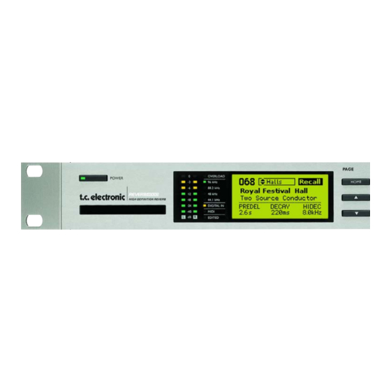
Page 8: Front Panel Overview
Rear panel POWER never be lit. to essential information/ switch must be used. operation, such as Recall, Store The Reverb 4000 auto sensing and Wizard functions plus I/O power supply accepts 110 to 96/88.2/48/44.1kHz LEDs and Utility. 240V. - Page 9 FRONT PANEL OVERVIEW F1 - PRE DELAY wheel STORE key UTILITY key Dedicated parameter adjust Press to store the current The Utility menu holds wheel. Always adjusts the preset in a user location. User settings for: value of the parameter location can be selected using MIDI, Memory copy and displayed to the left of the...
-
Page 10: Rear Panel Overview
REAR PANEL Power Input Balanced Balanced Optical Sync AES/EBU S/PDIF MIDI 100 - 240V Analog Analog ADAT Input/ Input/ In/Out/ Inputs Outputs & Output Output Thru Power Switch S/PDIF Note: The USB connection is for passing control data only. Cables - wiring XLR to XLR XLR to Jack XLR to Jack... -
Page 11: Signal Flow Diagram
SIGNAL FLOW... - Page 12 TYPICAL SETUPS Connecting and Setting up the Reverb 4000 Standard analog setup Standard Send/Return Setup With this setup the Reverb is fed with an analog stereo signal from e.g. a mixer AUX section. Via the Input Ch. parameter found in the I/O menu it is possible to chose which Input channel to be processed.
- Page 13 It is assumed that the TC Icon software is correctly installed on you computer. Page 20 describes installation procedure. Connections • Connect the Reverb 4000 to a free USB port on your computer using a standard USB cable (supplied). This connection ensures communication with the TC Icon Software Editor.
-
Page 14: Front Panel Operation
FRONT PANEL OPERATION The Display The Reverb 4000 display is split into two main sections. • The Upper section changes depending on the selected functionality. • The Lower section always shows parameter values. These parameters can always instantly be adjusted using the F1, F2 and F3 VALUE wheels. -
Page 15: Recall
Parameters & current values Presets The options are: The Reverb 4000 holds 150 factory presets. These are arranged in various categories such as Halls, Rooms etc - see below. To make a simple Recall • Press Recall to ensure you are at the Recall Page. -
Page 16: Recall Wizard
Origin equivalent to changing the size of the room. We All of the presets in the Reverb 4000 derive suggest selecting Size according to from other top quality Reverb processors by TC application. -
Page 17: Store - Delete
STORE & DELETE - FRONT PANEL OPERATION To enter the Reverb 4000 Store mode press STORE Function Storing Mode Storing Location Name/Rename Parameters & current values Name Basics To enter or alter a preset name during storing Use the UP/DOWN keys to select function and... -
Page 18: Utility
Standard MIDI Control Change (MIDI CC), Range: 0 to 127 but all parameters can be controlled via MIDI Sets the Reverb 4000 own SysEx ID for Sysex. Complete Sysex documentation can be identification in larger MIDI setups. downloaded via www.tcelectronic.com... -
Page 19: Midi Out
Single Precision mode controlled using a combination of values sent In this mode Reverb 4000 sends parameter as MSB (Most Significant Byte/Coarse) and values when adjusting values using the F1, F2 LSB (Least Significant Byte/Fine). -
Page 20: Midi Mapping
Select which incoming program change to map, and which preset to map to. Example: You wish to send program change 1 to the Reverb 4000 and recall preset 30 in Bank 1 (Rooms). Use the following setting: Map From Map To... -
Page 21: Bypass
Max level must be correctly set to match the Outputs. In a mastering situation you can even device to which the Reverb 4000 is connected. feed the dry signal through the 4000 with no degradation. The Dry Level and Digital Input... -
Page 22: Digital Output
I/O MENU - FRONT PANEL OPERATION Analog Offset Digital Output Input Offset Dither Range:The range is relative to the set Analog Range: 8, 16, 20, 24, Off Max parameter. Determines to what bit truncation should be The Analog Max parameter sets ideal interface made. -
Page 23: Installation
The TC Icon Software Editor is a generic Software Editor that currently controls the following products by TC Electronic: System 6000, DB-8, P2 and Reverb 4000. In this section only subjects relevant for usage with the Reverb 4000 will be discussed. Requirements for running the TC Icon... - Page 24 INSTALLATION - OF THE TC ICON SOFTWARE EDITOR • Now specify at which location the Wizard should look for the appropriate driver. • The Wizard now finds the correct driver on the CD ROM. • Press “NEXT” • Press “Finish”. The Driver is now installed and you are all set to go.
-
Page 25: The Tc Icon Editor - Quick Start
10/11. • Install software according to explanation on the previous page of this manual. • Power up the Reverb 4000 and start the TC Icon software on your computer. • Go to the Setup/Devices/Select page. • Press the DETECT key. The TC Icon Editor will scan the system and find the connected units. -
Page 26: Basic Operation
Press one of the units indicated on that page to access the unit. Auto page This page is for time-code operations and redundant when operating a Reverb 4000. Operating pages The preset is not stored by entering the ICON key name and pressing ENTER. -
Page 27: Preset Structure
“ALL” if you do not want to limit the selection by that Recall specific parameter. The Reverb 4000 holds: - 150 Factory presets. - 100 User locations for customized presets. - 100 User locations on a PCMCIA Card. -
Page 28: Preset Handling
Select Size according to application. • Press STORE. Info Wizard Options Origin All of the presets in the Reverb 4000 derive from other top quality reverb processors by TC Electronic. Info To each preset a short Info-text of max. 64 Options characters can be entered. - Page 29 If you have already stored banks on your computer this is where these files will appear. To Bank Select to which Reverb 4000 bank you wish to copy the selected bank to. To File Select “To File” if you wish to back-up the selected bank to your hard disk.
-
Page 30: System I/O - Page
Only the signal present on the Right Input is processed. Clock Select Clock select Range: Internal 44.1kHz (88.2@Double Rate) Internal 48kHz (96@Double Rate) Digital In Word Clock Locked Clock Indicates whether the Reverb 4000 is locked to the clock present on Digital Inputs. -
Page 31: Levels Page
0 to 22dBU (1dB steps) To achieve best “signal to noise ratio” the Max I/O level must be correctly set to match the device to which the Reverb 4000 is connected. Example: If the Mixers Max I/O level is 18dBu, the Max I/O Level parameter should be set to that value. -
Page 32: Midi Page
MIDI PAGE Card Bank Incoming Program Changes are mapped to recall presets from the Card bank. This requires that a Reverb 4000 formatted PCMCIA card is inserted in the Card slot. Custom Map Maps incoming program changes according to the Custom map settings. These settings are set via the Map page. -
Page 33: System Map Page
02 will map to preset 2 in Bank 1 etc. This is a “MIDI Custom Program Map page”, where you can customize how the Reverb 4000 should map incoming program changes. First of all the general MIDI settings must be set up at the MIDI page. -
Page 34: Net And Card
• Place the file in the folder: “My Documents” operated. • Then press the “Dump Binary File To Card” key Network Identification To load the Software to a Reverb 4000 from the The Network identifier merely serves as a PCMCIA card: name for easy recognition. It is especially •... - Page 35 SYSTEM - UI - Icon Views Trim On the Icon Setup page two sub-pages are available for controlling the TC Icon appearance. Fader appearance Press the value field to activate the Trim Three options are available. Changes will take function. With the Trim function a higher value place next time you open the TC Icon.
- Page 36 Subtle discrimination between The large reverb and room simulation palette of reflection patterns of individual sources can High end reverbs by TC Electronic allows the make all the difference in the world when it user to choose whatever principle suits a comes to obtaining depth, expression and present need.
- Page 37 GENERIC REVERB INTRODUCTION Source Reverb Cons • Require more sends or direct feeds than Generic Reverb types • No advantage on composite signals • Not ideal for moving sources Sampling Reverb Sampling reverbs present a variation of the Source theme: An impulse response is taken from an actual room based on a specific source and pick-up position.
- Page 38 TC Icon views. At the end of each algorithm section a table illustrates how the parameters are organized in the Reverb 4000 as stand alone unit. Multipliers - General Multipliers are typically used to specify a given Decay time in relation to a Master Decay.
- Page 39 High order reflections are often more diffuse than low order Early Level ones. In Reverb 4000 this effect is emulated by Range: Off to 0dB assigning individual diffusion characteristics to Adjusts the level of the Early Reflections from each reflection.
- Page 40 VSS-4 Positions Decay Crossover Range: Lo Decay R 30º, R 15º, R 7º, C 0º, L 7º, L 15º, L 30º Range: 0.01 to 2.5 Sets the location of the two Input sources. Decay multiplier in relation to the Master Decay, Depending on the Location Type the number of for the frequencies below the Lo Xover setting.
- Page 41 VSS-4 Gloss page In the Reverb 4000 user interface the parameters of this algorithm are organized as follows: Home PREDEL DECAY HIDEC MIDI CC: MIDI CC: MIDI CC: 22/54 (DP) 23/55 (DP) 24/56 (DP) (SP) (SP) (SP) Levels EARLY REVERB...
-
Page 42: Introduction
VSS-3 Introduction Hi Decay Range: 0.01 to 2.5 The VSS-3 algorithm is a multipurpose Multiplier for the frequencies above the Hi algorithm, that with the comprehensive amount Xover frequency. of parameters in both the Early Reflection section, the Reverb diffuse field and modulation Levels section opens for numerous flavors. - Page 43 VSS-3 Reverb page Phonebooth Bathroom Smallroom Carpark Swim Stadium Airport Street Alley Piazza Forest Pick the type that best compliments your material or best represents the effect you are going for. Early Size Reverb Range/Type: Small, Medium or Large Reverb Type Changes the size of the Early Type parameter.
- Page 44 VSS-3 Hi Cut Hi Decay Range: 20 to 20kHz Sets the Decay time for the High-end Filter that allows you to remove high frequencies of the Reverb diffuse field. frequencies from the Reverb. Lo Crossover Hi Soften Range: 20Hz to 500Hz Range: -50 to +50 Sets the frequency at which the transition from Hi Soften is a special filter used to "soften"...
- Page 45 VSS-3 Space Modulation In the Reverb 4000 user interface the parameters of this algorithm are organized Space Mod. Type as follows: (Off, Normal, Fast, Slow, MidFreq, Sync) Selects the type of Space Modulation. Space Mod. Rate Range: -100, default, +100...
-
Page 46: Nonlin-2
NONLIN-2 Introduction Attack Range: 0 - 500ms NonLin is an Effect Reverb with controllable Sets the Attack time (= build up) of the Reverb Envelope, Attack, Hold and Release. It is Envelope. capable of generating compact Vocal Ambience, dramatic eighties drum and Max. - Page 47 Applies the selected amount of "Twist" to the Hi cut on the Reverb Input. Reverb. In the Reverb 4000 user interface the When the Twist Ratio is set at 0%, Twist parameters of this algorithm are organized Type has no effect.
-
Page 48: Dvr-2
DSP power to mimic artifacts of old complementary to Source Reverb, and both hardware, the algorithm can also be put in a types are at disposal in the Reverb 4000. High Resolution mode. Using this function, the noisefloor is much lower, but use your own ears... - Page 49 DVR-2 Hi Decay In the Reverb 4000 user interface the Range: 0.5 to Max. parameters of this algorithm are organized Decay multiplier for hi frequencies. For a x1.0 as follows: setting, high frequency decay will equal the Decay setting. Home...
-
Page 50: Vss-4 Ts
VSS-4 TS (TRUE STEREO) Main page Rev1/Rev2 page Reverb Reverb 1 - Reverb 2 Decay Link Master Decay parameter. This parameter is The Link mode is used to link parameters also found on the Main page. between the Reverbs 1 and 2. E.g. if “Link 1+2” is selected the Master Decay of both Reverb 1 Rev. - Page 51 VSS-4 TS (TRUE STEREO) Hi Cut In the Reverb 4000 user interface the Range: 20Hz to 20kHz parameters of this algorithm are organized Determines the Hi Cut frequency. as follows: Hi Soften Smoothen the High End frequencies. Home Decay PREDEL...
-
Page 52: Ambiator
Range: Off to 0dB Adjusts the Wet level of the algorithm. Dry Level Range: Off to 0dB Sets the amount of Dry signal. In the Reverb 4000 user interface the Main parameters of this algorithm are organized Size as follows: Range: 0.5 to 2... - Page 53 Diffuse Reverb 4 is a new Stereo In, Stereo Out Range: -50 to +50 algorithm making its debut in Reverb 4000. This Sets the amount of Diffuse is a 2003 version of a Generic Reverb, suited for composite material and main microphone Tweak processing.
-
Page 54: Reverb-4
REVERB-4 Modulation In the Reverb 4000 user interface the parameters of this algorithm are organized Type as follows: Range: dependent on Rev Type Variations of modulations over the Reverb Types. Home PREDEL DECAY HIFACT Rate MIDI CC: MIDI CC: MIDI CC:... -
Page 55: Appendix
APPENDIX - MIDI IMPLEMENTATION REVERB 4000 - HIGH DEFINITION REVERB Function Transmitted Recognized Remarks Basic Channel Default Changed 1-16 OMNI-1-16 Mode Default Messages Altered Note Number True Voice Velocity Note ON Note OFF After Touch Key’s Channel Pitch Bend Control Change... -
Page 56: Technical Specifications
APPENDIX - TECHNICAL SPECIFICATIONS Digital Inputs and Outputs Connectors: XLR (AES/EBU) RCA Phono (S/PDIF) Optical (Tos-link, ADAT) Formats: AES/EBU (24 bit), S/PDIF (24 bit), EIAJ CP-340, IEC 958, EIAJ Optical (Tos-link), ADAT Lite pipe (24 bit) Output Dither: HPF/TPDF dither 8-20 bit, independent dithered output Word Clock Input: RCA Phono, 75 ohm, 0.6 to 10 Vpp Sample Rates:... - Page 57 APPENDIX - TECHNICAL SPECIFICATIONS Environment Operating Temperature: 32° F to 122° F (0° C to 50° C) Storage Temperature: -22° F to 167° F (-30° C to 70° C) Humidity: Max. 90 % non-condensing PCMCIA Interface Connector: PC Card, 68 pin type 1 cards Standards: PCMCIA 2.0, JEIDA 4.0 Card Format:...
-
Page 58: Preset List
PRESET LIST - HALLS No Name Preset Derrives from Algorithm Large Hall S-6000 VSS-4 Crystal Hall Soft Hall S-6000 Rev-4 Back There M-3000 VSS-3 Studio 40x40 ft M-3000 VSS-3 Rich Hall VSS4 Wooden Chamber VSS4 Wiener Halle VSS4 Concert Gebouw VSS4 DTuned Hall VSS4... - Page 59 PRESET LIST - ROOMS No Name Preset Derrives from Small Blanket Room S-6000 Church Coffee House S-6000 Dirty Room S-6000 Puk Drum Ambience M-3000 80X80 feet Box S-6000 DrewRoom <M5k> HomeRoom <M5k> Library Spanking Room DTuned Ambience Cozy Corner S-6000 Live 2 S-6000 Small Studio...
- Page 60 PRESET LIST - PLATES No Name Preset Derrives from Algorithm EMT 250 S-6000 DVR-2 Long Vocal S-6000 DVR-2 EMT 140 S-6000 Rev-4 SteelPlate <M5> VSS3 GoldPlate <M5> VSS3 Pure Plate Rev4 Vocal Plate+Delay DVR2 Mellow Plate VSS3 Chorused Plate DVR2 DTuned Plate Rev4 Dark Room...
- Page 61 PRESET LIST - EFFECTS No Name Preset Derrives from Algorithm Tight NonLin S-6000 NONLIN-2 AMS NonLin A S-6000 NONLIN-2 Garage Gate S-6000 NONLIN-2 Cheap Spring S-6000 Rev-4 Light Starburst S-6000 NONLIN-2 TajMahal <M5> VSS3 AutoPan Gate Nonlin2 Xplode Gate Nonlin2 Reverse Ramp Nonlin2 Dixie Chicken...
Need help?
Do you have a question about the REVERB 4000 and is the answer not in the manual?
Questions and answers