
Related Manuals for TC Electronic P2 Level Pilot


Summary of Contents for TC Electronic P2 Level Pilot
- Page 1 LEVEL PILOT A A D D M M I I N N I I S S T T R R A A T T O O R R ’ ’ S S M M A A N N U U A A L L...
-
Page 3: Important Safety Instructions
IMPORTANT SAFETY INSTRUCTIONS The lightning flash with an arrowhead symbol within an equilateral triangle, is intended to alert the user to the presence of uninsulated "dangerous volt- age" within the product's enclosure that may be of sufficient magnitude to constitute a risk of electric shock to persons. -
Page 4: Certificate Of Conformity
Certificate Of Conformity TC Electronic A/S, Sindalsvej 34, 8240 Risskov, Denmark, hereby declares on own responsibility that following products: P2 - Level Pilot - that is covered by this certificate and marked with CE-label conforms with following standards: EN 60065... -
Page 5: Table Of Contents
Preset Structure and handling: Recall/Store/ Delete ... . .16 Cloning P2’s ....18 System I/O Page Clock Preferences . -
Page 6: Introduction
Factory loaded with a broad selection of World Standard Presets the P2 can be used right out of the box. However, via the TC Icon PC Editor, suitable presets can be built by the Administrator and various lock functions can be applied to ensure no unintended change of settings by the daily User. -
Page 7: Quick Start
Installation of TC Icon Editor Software Enter CD, open directory, run Setup and follow instructions. Connecting P2 • Connect a PC COM port to the P2 RS232 In. If possible, notice which computer COM port QUICK START you have connected to. -
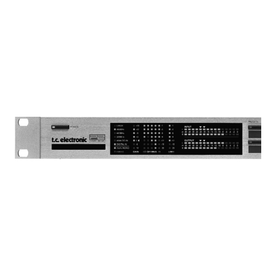
Page 8: Front Panel Overview
48/44.1/32 kHz LEDs Indicates current Sample Rate. ANALOG IN/DIGITAL IN Indicates currently selected Input type. DUAL MONO LED Indicates that the P2 is operating in Dual mono mode. EDITED LED Indicates that the currently recalled preset has been edited but not stored. - Page 9 Use the supplied lithographic crayon or similar. WIZARD key Using the Wizard function the P2 listens to a section of the program material; analyzes and thereafter automatically adjusts settings using the ALC to achieve optimal level thus keeping dynamics intact.
-
Page 10: Rear Panel Overview
Power Input Balanced 100 - 240V Analog Inputs Power Switch RS232 : For connecting to a PC. Use a standard 9 pin Sub D cable. (Supplied) GPI In : Use standard stereo 1/4” jack. (not supplied) : Use standard shielded 75 Ohm Coax cable with BNC connectors. (not supplied) XLR to XLR REAR PANEL Balanced... -
Page 11: Signal Flow Diagram
SIGNAL FLOW... -
Page 12: Typical P2 Setups
Cloning P2’s using a standard PCMCIA card Once the Administrator have designed and setup presets for various applications using the TC Icon PC Editor, other P2’s in the house may be easily cloned using a standard PCMCIA card. In other words; it is NOT necessary to hook up every single P2 to a computer to set these up. -
Page 13: Front Panel Operation
Administrator via the TC Icon Editor. Lock The Administrator can setup various lock functions/modes for the P2 via the System/ Front page in the TC Icon PC Editor. Setting up via the TC Icon Editor is explained later in the manual. - Page 14 Delay is active in bypass. Bypass is bit transparent. The Delay time is set on the Engine Main page. Note: If P2 is used with data-reduced signals such as MPEG, DOLBY E or DTS, use one of the Codec Bypass modes described above.
-
Page 15: The Tc Icon Pc Editor
• A folder called: TC Icon Software Editor + MS Installer (use this if MS Installer is not on your computer - see below) • The P2 Manual in PDF format. Installing - the TC Icon Software Editor Your computer probably holds the required MS Installer program and you only need to run the file called: TC Icon x.xx.msi... -
Page 16: The Tc Icon Editor
Note to which COM port you connect the P2. • Install software according to explanation on the previous page of this manual. • Power up the P2 and start the TC Icon software on your computer. • Go to the Select/Port page to select which COM(1-4) port you you have connected to. -
Page 17: Basic Operation
Press one of the units indicated on that page. Auto page This page is redundant when operating a P2. Fig 2 - Operating pages Press the Icon Link key in the upper left corner to select these pages. -
Page 18: Preset Structure And Handling: Recall/Store/ Delete
U1 is equivalent to presets that can be recalled from the eight Front panel PRESET keys. Factory Presets: P2 comes loaded from the factory with a collection of general purpose Factory presets organized in banks of 8. Store - Delete To store a preset: •... -
Page 19: Bank Handling
U8) to any user bank location (U1 to U8) or to your harddisk. From Bank On this page you select which bank on the P2 you wish to copy from. From File If you have already stored banks on your computer this is where the files will appear. -
Page 20: Cloning P2'S
Loading/Cloning P2 using the Clone Card. Once the clone card has been created on the P2 hooked up via the TC Icon PC Editor it is time to transfer the card data to other P2’s in your facility. -
Page 21: System Front Page
SYSTEM - I/O PAGE Digital Output Dither Range: 8, 12, 14, 16, 18, 20, 22, 24, off P2 processes internally at 48 bit resolution. Dither must be set to match downstream devices. Status Bits Select whether the P2 should send out AES/EBU or S/PDIF status bit information. - Page 22 bet ee 8 p esets ring sleeve R2, 22k R1, 12k GPI Technical specifications Inside the processor, a 10kohm resistor connects the Tip terminal to a +5V power supply. When nothing is connected to the GPI input, the input voltage therefore is +5V. Resistors can be used to pull down the voltage as suggested in Fig 1.
-
Page 23: System - Front Page
Frame compensation Delay. Actual Delay time can be tapped using a connected momentary switch. Calibrate Use this function to calibrate P2 to a connected GPI controller. E.g. TC Master Fader (not supplied). To Calibrate: • Connect GPI Controller to GPI Input and press CALIBRATE. -
Page 24: Lock Activation
SYSTEM - NET PAGE & ICON VIEWS Disable: No lock function is active. Lock Wizard: Wizard function is disabled and cannot be activated via the front panel WIZARD key. Lock Recall: No presets can be recalled via the eight front panels preset keys but the Wizard function is enabled. -
Page 25: Color Page
Select type of digital Input format. Clock Select Range: Internal 44.1, Internal 48k, Word Clock, Ext DI Select to which clock the P2 should sync. Digital SRC Range: On/Off Sets whether the P2 should perform Sample Rate conversion on the incoming clock or not. -
Page 26: Main Page
If the 5 band Compression sections is set to use a very short Attack times (up to approx 10- 15ms) overshoots may occur. The Look Ahead function allows the P2 to evaluate the material just before processing and artifacts can thereby be prevented. - Page 27 Configuration Processing Overview DELAY FILTERS Analog Digital Delay: Link/Unlink DELAY FILTERS Analog Digital 24 Bit Reference Level Reference Level defines the standard operating level, and scales the Threshold and Target Level parameters of the Loudness control and Multiband section. The Threshold of the Limiter is not influenced by this setting, but is always relative to 0dBFS.
-
Page 28: Processing Modes
MAIN PAGE Processing Modes - Stereo. In this mode the Loudness, EQ and Multiband sections operate in tandem: Whatever gain change is applied to one channel, is applied to the other. Also, many parameters have mutual left and right controls. - Dual Mono. - Page 29 Level Trim Range: -18dB to + 18dB Because P2 operates with 48 bit precision on all audio internally, it is possible to correct loudness manually without the risk of overloads. The Level Trim can be used for permanent off-sets or live loudness adjustments.
-
Page 30: Eq Page
EQ Page Introduction This digital EQ features a three-band parametric EQ with high- and low-pass filters switchable between Notch, Parametric, Shelving and Cut filters. The needle sharp notch filter has a range down to 0.01 octave and the shelving filters has a variable slope, ranging from gentle 3 dB/oct over 6 and 9 to 12dB/oct. - Page 31 Shelving Filter Notch Filter - Narrow Type Cut Filter - Bessel type EQ PAGE Cut Filter - Butterworth type Freq Press Freq and use Faders 1 to 3 to adjust frequence for each of the three bands. Range - Lo band Range - Mid band Range - Hi band Gain...
- Page 32 Type Press TYPE and use Faders 1-3 to set BW value for each of the three EQ bands. Range for the Notch filter: Lo BW : 0.02oct to 1oct Mid BW : 0.02oct to 1oct Hi BW : 0.02oct to 1oct Range for the Parametric filter: Lo BW : 0.1oct to 4oct...
-
Page 33: 5-Band Page
Xovers Press this button to access the four cross-over points between the five-bands. The parameters are Automatically assigned to faders 1-4. Parameter range: Xover 1: Off to 1.6kHz Xover 2: Off to 4kHz Xover 3: 100Hz to Off Xover 4: 250Hz to Off Defeat Thresh Range: -3 to -30dB This is a unique control which defeats gain from... -
Page 34: Limiter
5-BAND PAGE Try setting the Steer and/or Threshold parameters differently in the bands to hear the effect. High Steer values add more detail gain than low values, but remember that Threshold has to be negative to add detail gain at all. DXP Threshold relates to the Reference Level set on the Main page. -
Page 35: Appendix
Press LOCK (enter) to see current loaded boot software version. For service-purposes only. “V” - Operating software number Press LOCK (enter) to see current loaded P2 software version. “N” - Serial Number Press LOCK (enter)to see serial number for this unit. -
Page 36: Loading Preset Banks
APPENDIX Loading Preset Banks The P2 is loaded with the 8 presets from the Default F1 bank (see page 37). These are the presets accessible from the Front Panel . However, it is possible to load other banks into the front panel. To do this: •... -
Page 37: Technical Specifications
APPENDIX - TECHNICAL SPECIFICATIONS Digital Inputs and Outputs Connectors: XLR (AES/EBU), RCA Phono (S/PDIF) Formats: AES/EBU (24 bit), S/PDIF (24 bit), EIAJ CP-340, IEC 958 Output Dither: HPF TPDF dither 8-22 bit Word Clock Input: BNC, 75 ohm, 0.6 to 10 Vpp Sample Rates: 32 kHz, 44.1 kHz, 48 kHz Processing Delay:... -
Page 38: Selftest
Available from Software 1.20 and up. Accessing Self test • Press and hold the “BYPASS” key, while powering up to access the self test. • Press PRESET 8 to increase test number. • Press PRESET 4 to decrease test number. •... -
Page 39: Presets
PRESET LIST - SW 1.50 Name Screen Notes Default NAB Limit A Analog Input Limiter. US Std. SMPTE RP155 NAB Limit D Digital Input Limiter. US Std. SMPTE RP155 EBU Limit A Analog Input Limit. EU Std. EBU R68 EBU Limit D Digital Input Limit. - Page 40 PRESET LIST - SW 1.50 Name Screen Notes Reserved Reserved Reserved Reserved Reserved Reserved Reserved Reserved Reserved Live Mix Mix Pilot General purpose Mix Assistant. Digital In News News Mix Assistant. Digital In, Dual Mono Gameshow Gameshow Mix Assistant. Digital In Live Sports Live sports Mix Assistant.
- Page 41 PRESET LIST - SW 1.50 Name Screen Notes Reserved Reserved Reserved Reserved Reserved Reserved Reserved Reserved Reserved Live Mix STL Relax Radio STL Optimize. Shape: Flat STL Energy Radio STL Optimize. Shape: Loudness STL Sky Radio STL Optimize. Shape: Crisp STL Autobahn Radio STL Optimize.
Need help?
Do you have a question about the P2 Level Pilot and is the answer not in the manual?
Questions and answers