Table of Contents
Advertisement
Quick Links
Advertisement
Table of Contents

Related Manuals for Metronic DV3


Summary of Contents for Metronic DV3
-
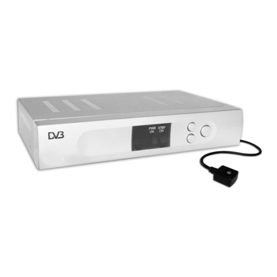
Page 3: Overview Of Equipment
Overview of equipment Front side of the receiver STBY Rear side of the receiver IR-IN COAXIAL Remote control RG405 DS1... - Page 4 Overview of equipment Front side of the receiver Infrared sensor for the signals of the remote control LED POWER LED is illuminated if the receiver is switched on or in standby mode LED STBY LED is only illuminated if the receiver is in standby mode CH+ key Switches to the next higher channel...
-
Page 5: Remote Control
Remote control Symbol Description Standby Switches on and switches to the standby mode ZOOM Enlarges TV image LIST Invokes TV channel list TIMER Invokes timer TEXT Invokes Teletext MUTE Turns off sound Multi-picture function, invokes thumbnail view Increases volume/cursor moves to the right In normal mode: invokes current channel list. -
Page 6: Preface
Preface This operating manual will help you in the • appropriate • safe usage of the digital satellite receiver, hereafter called as the receiver in short. We assume that the user of the receiver has overall knowledge regarding handling audio and video equipment. Every person who •... -
Page 7: Table Of Contents
Contents Preface....................6 Style features ..................6 Contents .................... 7 Safety instructions ................9 Basic safety instructions ............9 Appropriate usage ................12 Product Contents ................13 Description..................14 Receiver connection ..............17 LNB cable installation ............... 18 Connection with Scart cable ............. 20 Connection with phono cable ............ - Page 8 Switch between TV and SAT............40 Switch between TV and radio............40 ZOOM ....................40 LIST ....................40 AUDIO ....................41 EPG ....................41 Teletext ..................... 41 M/P Multi-picture................42 MUTE....................42 FAV....................42 RECALL.................... 42 Acoustic signal for directing the satellite antenna ......43 Sleep timer ..................
-
Page 9: Safety Instructions
Safety instructions Please read the safety instructions carefully before operating the receiver. Please follow all warnings and instructions on the equipment and in the operating manual. Basic safety instructions Electrical connection • Do not expose the receiver to rain as well as any kind of humidity to avoid risk of fire and electric shock. - Page 10 • Never allow children to play with or operate the antenna unit unless supervised. • Always ask qualified personnel to carry out maintenance jobs. Otherwise, you are putting yourself and others at risk. • Disconnect the receiver from the power source in case of operational disruptions.
-
Page 11: Explanation Of Safety Instructions
period of time, remove the batteries from the remote control. • Batteries may contain toxic agents. Therefore, dispose of the batteries immediately in an ecologically accepted manner according to the prevailing statutory regulations. Never throw the batteries into normal household waste. •... -
Page 12: Appropriate Usage
Appropriate usage The receiver receives uncoded digital channels (free-to-air) in a covered area. It is exclusively meant for this purpose and should only be used for the same. This also includes paying attention to all information in this operating manual especially that of safety instructions. -
Page 13: Product Contents
Product Contents Check the product contents after purchase. The product contents may vary according to the type of the receiver. Please follow the information on the packaging STBY Quantity Description Receiver Remote control unit Battery Typ LR 03/AAA/1,5 V External power pack IR extension lead Operating manual (not shown above) -
Page 14: Description
Description You can receive uncoded (free-to-air) digital satellite channels with the satellite system with a satellite antenna. The following satellites have been pre-programmed by the company: • Astra1 19° East • Hotbird 13E • Turksat 42E • Sirius2 5E • Amos 4W •... - Page 15 • Portuguese • Spanish • Turkish • Czech • Slovakian • Hungarian • Danish • Swedish • Croatian • Dutch • Greek • Norwegian Other features of the equipment: • Software update via satellite ASTRA 19° East or via the RS232 connection on the rear side of the device. •...
- Page 16 • List editor for broadcasting stations • Analogue sound output through Cinch connector (stereo), volume adjustment possible via remote control • AC3 coaxial output (digital-audio, SPDIF) • 2 Euro-SCART connections for TV and video set • Video output signal CVBS •...
-
Page 17: Receiver Connection
Receiver connection The receiver is connected with your satellite antenna by means of a coaxial cable. If necessary, you have to prepare a coaxial cable before connecting the receiver. Caution! Connect the receiver to the mains supply only after you have connected it to all equipment and the antenna properly. -
Page 18: Lnb Cable Installation
LNB cable installation (See the installation diagram on the next page) For the installation of the F connectors on the coaxial cable you need a knife (ideally a wire stripper) and side cutting pliers. Cut 8mm of the coaxial cable at each end up to the inner core. Carefully cut 10mm of the outer insulation so that the wire netting is exposed. -
Page 19: Installation Diagram
Installation diagram Fasten the F connector of the coaxial cable onto the “LNB IN” antenna connection of the receiver. Fasten the other end of the coaxial cable to the LNB. -
Page 20: Connection With Scart Cable
Connection with Scart cable Insert the Scart cable in the “TV Scart” Scart socket of the receiver. Connect the Scart cable to the TV set. Follow the operating manual of the TV set. Insert the Scart cable in the “VCR Scart“ Scart socket of the receiver if you want to connect a video set. -
Page 21: Connection Diagram
Connection diagram IR-IN COAXIAL... -
Page 22: Connection With Phono Cable
Connection with phono cable Connect the phono connectors of the audio cable to the “AUDIO R” and “AUDIO L” sockets of the receiver if you want to connect a stereo system. Caution! Strictly follow the instructions for connecting the audio cable given in the operating manual of your stereo system. - Page 23 Connection diagram IR-IN COAXIAL...
-
Page 24: Direction Of The Antenna
Direction of the antenna You must connect the LNB cable to LNB before directing the antenna. Caution! While connecting the LNB cable, the receiver must not be connected to the mains supply. Fasten the F-connector onto the connection of LNB on which the sealed socket is located. -
Page 25: Getting Started
Getting started Remote control Two Micro type batteries are required for the remote control: LR 03/AAA/1.5 V Open the battery compartment. Insert two batteries into the battery compartment paying attention to the indicated polarities and push the cover of the battery compartment carefully until the cover is locked. - Page 26 before connecting the external power pack or the 12 V cable of the receiver to the power source and starting the receiver. Insert the mains plugs of the connected equipment in the mains socket and switch it on. Switch on the AV channel of the TV set. Insert the power pack of the receiver in the mains socket.
-
Page 27: Adjustment Of Antenna
Adjustment of antenna The reception quality set by you in the antenna settings may not be optimal. In this case, you must do a fine adjustment of the antenna. For this procedure, please see the operating manual of your satellite system. By pressing the “INFO”... -
Page 28: Operation
Operation Screen-inlays while switching a channel When a channel is switched, an information bar is inlayed on the screen for 5 seconds (adjustable). In this information bar, you will find the following indications: Channel name Received satellite Current date Current time Storage location TXT symbol This symbol is displayed if the selected broadcasting station... -
Page 29: User Interface On The Tv Monitor
User interface on the TV monitor You can do individual settings of your receiver using the menus in the user interface. For this purpose, both the receiver and the TV set need to be switched on and connected by a SCART cable. Press the “MENU”... -
Page 30: Menu Structure
Menu Structure Main menu Sub-menu Description Channel TV channel list See following text Radio channel list See following text (symbol: Delete all See following text Installation Antenna setting See following text Auto scan See following text (symbol: TP scan See following text satellite Preset Scan See following text... -
Page 31: Menu Navigation
Menu navigation Use the keys “CH+”, “CH-”, “V+”, and “V-” to navigate within the menus. The selected menu items are marked. Confirm your selection with the “OK” key. By pressing the “EXIT” key you can exit the menu again. Changes must be confirmed additionally. Apart from this, the numerical keys are required in further sub- menus. -
Page 32: Channel (Symbol: Tv)
Channel (symbol: TV) Sub-menu Description TV channel list 1 Favourite, 2 Move, 3 Find, 4 Sort, 5 Edit, 6 Type, ▲▼Select, V- V+ Group, OK Enter, EXIT Exit. Radio channel list as indicated above Delete all Deletion of the complete channel list. For this purpose: Enter password (factory setting 0000) and confirm warning message with Yes. - Page 33 5 Edit After entering the password (factory setting 0000), new selection options will appear. Sub-menu Description Edit 1 Delete, 2 Skip, 3 Lock, 4 Edit, 5 Create, 6 Del all, ▲▼Select, V- V+ Group, P+P- Page, EXIT Exit. 1 Delete By marking with key 1, selected channels can be marked to be deleted.
-
Page 34: Installation (Symbol: Satellite Antenna)
6 Type (channel group) Here, you can assign selected channels to determined channel groups (Types) as desired. Please confirm your selection with “OK”. You can exit the menu by pressing the "EXIT“ key. Installation (symbol: satellite antenna) Sub-menu Description Antenna Setup Satellite Satellite selection (example: Astra1 19°... - Page 35 The procedure is initiated via "Scan“. Preset Scan Scanning of preset frequencies (transponders). (Normal automatic scan)
-
Page 36: System Settings (Symbol: Gearwheel)
System settings (symbol: gearwheel) Sub-menu Description Language Language Selection of menu language (OSD) First audio Preselection of audio language (if offered by the broadcasting station) Second audio Preselection of audio language (if offered by the broadcasting station) TV system Display mode Selection of transmission system;... - Page 37 Table for timer setting Sub-menu Description Timer number Selection of timer number 1-8. Timer mode Repetition (once, daily, weekly, monthly, annually, off). With the setting “off“, the timer will be deactivated. Timer service Switching between programme timer and reminding function. Wake-up message With timer service setting “Message“.
-
Page 38: Setting (Symbol: Tools)
Setting (symbol: tools) Sub-menu Description Information Display of reception parameters. (This function can Activation of the acoustic tone signal via key 1. also be accessed directly via the "INFO" key.) Game Here, the three games: Tetris, Snakes and Othello are available. -
Page 39: Software Update Via Satellite
Software update via satellite The update has nothing to do with the storage of new TV channels. It is rather meant to update the system software of the receiver. Normally, the update is not required for a trouble-free operation of the receiver. You must direct your satellite system towards the satellite ASTRA 19°... -
Page 40: Keys With Special Functions
Keys with special functions Switch between TV and SAT With the “TV/SAT” key you can switch between TV and satellite functions. (This function has to be provided by your TV set). Press the “TV/SAT” key until you have set the desired function. Switch between TV and radio With the “TV/Radio”... -
Page 41: Audio
AUDIO With the “AUDIO” key you can select the audio track if a broadcasting station offers multi-channel sound. Additionally, you can activate the Dolby Digital mode here. (For this purpose you additionally need a Dolby Digital system. The connection is made on the rear of the device via the COAXIAL socket). -
Page 42: M/P Multi-Picture
M/P Multi-picture Press the “M/P“ key to go to the multi-picture mode. Now, 9 channels will appear simultaneously on your screen, starting with the current channel. With the keys CH-, CH+, V- and V+, you can move the yellow marking bar. The marked channel is displayed in real time. All other channels are displayed as freeze images. -
Page 43: Acoustic Signal For Directing The Satellite Antenna
Acoustic signal for directing the satellite antenna For this purpose, press the “INFO” key. Apart from the current reception parameters, you will get information on the signal strength and quality. Additionally, you can activate an acoustic signal by pressing key 1. An acoustic signal is transmitted via the TV set. -
Page 44: Dismantling
Dismantling Disconnect the receiver and connected equipment from the power supply. Loosen the LNB cable from the receiver and LNB. Take the batteries out of the remote control, if you will not use the receiver for a longer period of time. Pack the receiver, the remote control, the 2 batteries, the external power pack and the 12V cable for the cigarette lighter into the cardboard box. -
Page 45: Troubleshooting
Troubleshooting Symptom Possible cause and remedy Satellite cannot be Example: Astra1 19° East found, or no signal Key 1 (presetting: “ARD“) Key “INFO“ (“ARD“, FR11837) Signal AND quality are both at 0% Direct vertical reflector towards south. Turn some millimetres to the left, wait approx. 3 seconds and repeat until signal AND quality are displayed. - Page 46 No image, no sound, The satellite antenna has been directed to a wrong signal strength OK, satellite. no signal quality Bad reception of: Wireless telephone is disturbing (DECT standard). Put Sat1, Pro7, Vox, the telephone to another place, use a better satellite N24, DSF, etc.
-
Page 47: Technical Specifications
Technical specifications Receiver Dimensions in mm (W × D × H) 210 × 145 × 45 Weight in grams Receiver 660 g Remote control 80 g (without batteries) Input frequency range 950 MHz ~ 2'150 MHz IF band width 55 MHz / 8 MHz (below 5MS/s) LNB power supply 13V/18V GS, 0.30 A max. -
Page 48: Manufacturer
Manufacturer Dear customer, Past experience has shown that many complaints can be settled through a simple telephone call or visiting our website. In case problems should arise with your device we kindly ask you to contact our service hotline first. Proceeding like this will spare you time and possible irritation. -
Page 49: Declaration Of Conformity
Declaration of conformity The manufacturer hereby declares conformity with the following guidelines and standards for this product: Guideline for low voltage, 73/23/EEC • EN 60,065 Guideline for electromagnetic compatibility, 89/336/EEC • EN 55,013 • EN 55 020 • EN 61000-3-2 •... -
Page 50: Glossary
Glossary Alternating Current Connection for alternating current Direct Current Connection for direct current Cinch connector Coaxial connector for connecting TV set or stereo system. DiSEqC Digital Satellite Equipment Control Digital system, with which the receiver can control different components of the external unit. It is especially used for selecting from multiple satellite positions (for example Astra and Eutelsat).
Need help?
Do you have a question about the DV3 and is the answer not in the manual?
Questions and answers