
Related Manuals for Fujitsu PRIMERGY BX400 S1


Summary of Contents for Fujitsu PRIMERGY BX400 S1
-
Page 1: Blade Server
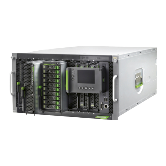
Operating Manual - English PRIMERGY BX400 S1 Blade Server System Unit Operating Manual December 2012... -
Page 2: Copyright And Trademarks
– The contents of this manual may be revised without prior notice. – Fujitsu assumes no liability for damages to third party copyrights or other rights arising from the use of any information in this manual. – No part of this manual may be reproduced in any form without the prior written permission of Fujitsu. - Page 3 Before reading this manual For your safety This manual contains important information for safely and correctly using this product. Carefully read the manual before using this product. Pay particular attention to the accompanying manual "Safety Notes and Regulations" and ensure these safety notes are understood before using the product.
- Page 4 Please consult the sales staff of Fujitsu if intending to use this product for high safety use. Measures against momentary voltage drop This product may be affected by a momentary voltage drop in the power supply caused by lightning.
- Page 5 Only for the Japanese market: Although described in this manual, some sections do not apply to the Japanese market. These options and routines include: – CSS (Customer Self Service) Operating Manual BX400 S1...
- Page 6 Operating Manual BX400 S1...
-
Page 7: Table Of Contents
Contents Introduction ......11 Concept and target groups for this manual ..11 Documentation overview . - Page 8 Contents Instructions for connecting/disconnecting cables ..58 Installation and operation ....59 Control and display elements .
- Page 9 Contents 8.2.7 Connection Blade 8Gb FC Pass Thru 18/18 ..108 8.2.8 Connection Blade DCB SW 10Gb 18/6+6 ... . 110 8.2.9 Connection Blade FEX B22F 10Gb (Cisco) .
- Page 10 Contents Operating Manual BX400 S1...
-
Page 11: Introduction
This operating manual is intended for those responsible for installing the hardware and ensuring that the system runs smoothly. It contains all the information you need to put your PRIMERGY BX400 S1 system unit into operation. To understand the various expansion options, you will need to be familiar with the fields of hardware and data transmission and you will require a basic knowledge of the underlying operating system. -
Page 12: Documentation Overview
More information on your PRIMERGY BX400 S1 system unit can be found in the following documents: – "Quick Start Hardware - PRIMERGY BX400 S1" leaflet " は じ めにお読み く だ さ い -PRIMERGY BX400 S1" for the Japanese market (only included as a printed copy) – "Safety Notes and Regulations" manual "... -
Page 13: Performance Features
Management Blade S1 User Interface Description" Performance features Customer Self Service (CSS) The Fujitsu Technology Solutions Customer Self Service (CSS) concept enables you to identify and replace the affected component yourself in the case of certain error scenarios. In the CSS concept, you can replace the following components yourself in the event of an error: –... - Page 14 Connection blades The PRIMERGY BX400 S1 system unit has four slots for connection blades on the back. These provide the installed server blades with connections to the Ethernet LAN as well as to SAN environments and Infiniband environments.
- Page 15 Introduction Connection Blade GbE Switch/IBP 36/8+2 (SB11) 36 internal 1-Gbit/s ports to the server blades 8 external 1-Gbit/s ports through RJ45 connections 2 external 10-Gbit/s ports through SFP+ modules via fiber-optic or copper cable 1 internal stacking port to the midplane of the BX400 S1 system unit 1 external stacking port through a CX4 connection Installable in all connection blade slots This connection blade can be used as a layer-2 switch or an...
- Page 16 Introduction Connection Blade 10 GbE Switch/IBP 18/8 18 internal 10-Gbit/s ports to the server blades 8 external 10-Gbit ports through SFP+ modules or active twinax cables (copper) Installable in all connection blade slots This connection blade can be used as a layer-2 switch or an Intelligent Blade Panel (IBP).
- Page 17 Introduction Connection Blade Ethernet Pass Thru 10Gb 18/18 18 internal 1/10-Gbit/s ports to the server blades 18 external uplink ports at 10 Gbit/s and 1 Gbit/s link speed through SFP+/SFP modules Installable in all connection blade slots 10 Gb Ethernet Pass Thru connection blades in slots CB2 (fabric 2) and CB3/4 (fabric 3) only support server blades that are fitted with 1Gb or 10 Gb Ethernet mezzanine cards or 10Gb CNA mezzanine cards.
- Page 18 Introduction Fibre Channel connection blades Fibre Channel connection blades only support server blades that are fitted with a Fibre Channel mezzanine card. Connection Blade 8Gb FC Switch 18/8 (Brocade BR5450) 18 internal 8-Gbit/s ports to the server blades 8 external ports through 8-Gb SFP+ modules or 4-Gb SFP modules Installable in slots CB3/4 (fabric 3) This connection blade is available in three license variants: –...
- Page 19 Introduction 10 Gb Ethernet / DCB connection blades Connection Blade DCB SW 10Gb 18/6+6 18 internal 10-Gbit/s ports to the server blades 6 external 10-Gbit/s Data Center Bridging (DCB) capable ports through Brocade branded SFP+ modules or SFP+ Twinax cables 6 external FC ports through 8-Gb SFP+ modules or 4-Gb SFP modules Installable in all connection blade slots The connection blade DCB SW 10Gb 18/6+6 in slots CB2...
- Page 20 Introduction Infiniband connection blades Connection Blade Infiniband Switch 40 Gb 18/18 18 internal 40-Gbit/s ports to the server blades 18 external 40-Gbit/s Infiniband connections through QSFP modules Installable in slots CB3/4 (fabric 3), see figure "Connection blade slots" on page 120 Connection Blades Infiniband Switch 40 Gb 18/18 only support server blades that are fitted with an 40 Gb Infiniband mezzanine card (PY IB CX2 Mezz Card 40Gb 2 Port).
- Page 21 ASR&R (Automatic Server Reconfiguration and Restart) restarts the system in the event of an error and automatically "hides" the defective system components. The PDA (Prefailure Detection and Analyzing) technology from Fujitsu Technology Solutions analyzes and monitors all components that are critical for system reliability.
- Page 22 Server management is implemented using the ServerView Operations Manager supplied and the PDA (Prefailure Detection and Analysis) technology from Fujitsu. PDA reports the threat of a system error or overload at an early stage, allowing preventive measures to be taken.
- Page 23 Introduction The redundant management blades and the optional remote test and diagnostics system ServerView Remote Management allows the PRIMERGY BX400 S1 blade servers to be serviced from a remote system. This enables remote diagnosis for system analysis, remote configuration and remote restart should the operating system or hardware fail.
-
Page 24: Notational Conventions
Introduction Notational conventions The following notational conventions are used in this manual: Text in italics indicates commands or menu items. "Quotation marks" indicate names of chapters and terms that are being emphasized. describes activities that must be performed in the order Ê... -
Page 25: Technical Data
Introduction Technical data Electrical data (hot-plug power supply unit) Rated voltage range 100 - 120 V / 200 - 240 V Frequency 50 Hz-60 Hz Max. rated current 45 A (100 - 120 V) / 22.5 A (200 - 240 V) Effective power 1785 W (240 V) 1200 W (100 V) Apparent power... - Page 26 Introduction Certification Product safety Global Europe ENEC Germany GS, CE USA/Canada / CSA Japan VCCI China/Taiwan BSMI Mechanical specifications Width 445 mm Depth 785 mm Height 267 mm or 6 HU Weight Max. 98 kg (depending on the configuration). Operating Manual BX400 S1...
- Page 27 Introduction Ambient conditions Environment class 3K2 EN 60721 / IEC 721 Part 3-3 Environment class 2K2 EN 60721 / IEC 721 Part 3-2 Temperature: Operation (3K2) 10 ºC ..35 ºC Transport (2K2) -20 °C ..60 °C Humidity 10% ... 85% (non condensing) Condensation during operation must be avoided! Noise level Sound power level L...
- Page 28 Introduction Operating Manual BX400 S1...
-
Page 29: Installation Steps, Overview
Installation steps, overview This chapter provides an overview of the installation steps for your BX400 S1 system unit. Links take you to sections where you can find more detailed information about the respective steps: Ê First read the chapter "Important notes" from page 31, particularly the... - Page 30 Installation steps, overview Operating Manual BX400 S1...
-
Page 31: Important Notes
Important notes This chapter provides safety instructions which you must observe when handling your system. Safety instructions The following safety instructions are also provided in the manual "Safety Notes and Regulations" or " 安全上のご注意 ". This device meets the relevant safety regulations for IT equipment. If you have any questions about whether you can install the server in the intended environment, please contact your sales outlet or our customer service team. - Page 32 Important notes Before starting up CAUTION! During installation and before operating the device, observe the ● instructions on environmental conditions for your device (see "Ambient conditions" on page 27). If the system unit has been moved from a cold environment, ●...
- Page 33 Important notes CAUTION! Make sure that the power sockets on the device or the grounded ● mains outlets are freely accessible. The On/Off button or the main power switch (if there is one) does not ● disconnect the device from the mains voltage. To completely disconnect it, you must remove all the power plugs from the power outlets.
- Page 34 Important notes CAUTION! Proper operation of the device (in accordance with IEC 60950- ● 1/EN 60950-1) is only ensured if the casing is fully assembled and the rear covers for the installation bays are in place (electric shock, cooling, fire protection, interference suppression). Install only system extensions that satisfy the requirements and rules ●...
- Page 35 Important notes Working with CDs/DVDs/BDs and optical drives When working with devices with optical drives, these instructions must be followed. CAUTION! Only use CDs/DVDs/BDs that are in perfect condition, in order to ● prevent data loss, equipment damage and injury. Check each CD/DVD/BD for damage, cracks, breakages etc.
- Page 36 Important notes Do not contaminate the CD/DVD/BD surface with fingerprints, oil, ● dust, etc. If dirty, clean with a soft, dry cloth, wiping from the center to the edge. Do not use benzene, thinners, water, record sprays, antistatic agents, or silicone-impregnated cloth. Be careful not to damage the CD/DVD/BD surface.
- Page 37 Important notes Batteries CAUTION! Incorrect replacement of batteries may result in a risk of explosion. ● The batteries may only be replaced with identical batteries or with a type recommended by the manufacturer (see the Technical Manual of the server blade). Do not throw batteries into the trash can.
- Page 38 Important notes Modules with Electrostatic-Sensitive Devices Modules with electrostatic-sensitive devices are identified by the following sticker: Figure 1: ESD label When you handle components fitted with ESDs, you must always observe the following points: Switch off the system and remove the power plugs from the power outlets ●...
-
Page 39: Ce Conformity
Only unpack the system unit at the place where you want to set it up. Ask someone for help with carrying the system unit. Because the ● PRIMERGY BX400 S1 system unit is large and heavy, at least two people are needed. Before lifting the system unit, remove all server blades, storage ●... -
Page 40: Notes On Installation Into The Rack
Important notes Notes on installation into the rack CAUTION! For safety reasons, at least two people are required to install the ● system unit in the rack because of its weight and size. (For the Japanese market, please refer to " 安全上のご注意 ".) Before lifting the system unit, remove all server blades, storage ●... -
Page 41: Environmental Protection
Important notes Environmental protection Environmentally-friendly product design and development This product has been designed in accordance with the Fujitsu standard for "environmentally friendly product design and development". This means that key factors such as durability, selection and labeling of materials, emissions, packaging, ease of dismantling and recycling have been taken into account. - Page 42 Details regarding the return and recycling of devices and consumables within Europe can also be found in the "Returning used devices" manual, via your local Fujitsu branch or from our recycling center in Paderborn: Fujitsu Technology Solutions Recycling Center D-33106 Paderborn Tel.
-
Page 43: Installing The Hardware
Installing the hardware CAUTION! Follow the safety instructions in chapter "Important notes" on ● page The system unit must not be exposed to extreme environmental ● conditions (see "Ambient conditions" on page 27). Protect the system unit from dust, humidity and heat. The system unit must be acclimatized to its operating environment for ●... -
Page 44: Installation Procedure
Installing the hardware Installation procedure The following installation steps are described in detail in the following sections of this chapter: Unpacking the system unit (see "Unpacking the system unit" on page 44). ● Installing the system unit in the rack (see "Installing/removing the system ●... -
Page 45: Setting Up The Floorstand Model
Installing the hardware Setting up the floorstand model If you are not installing a PRIMERGY BX400 S1 system unit floorstand model, skip this section and continue reading at section "Installing/removing the system unit" on page CAUTION! Follow the safety instructions in chapter "Important notes"... -
Page 46: Installing/Removing The System Unit
Installing the hardware Installing/removing the system unit CAUTION! At least two people are needed to lift the system unit. (For the Japanese market, please refer to " 安全上のご注意 ".) For configurations below 32 kg: At least two people are needed to lift the system unit. - Page 47 Please observe the safety information and notes on rack mounting in chapter "Important notes" on page Fujitsu rack systems The rack systems from Fujitsu support the installation of PRIMERGY servers: – PRIMECENTER rack – PRIMECENTER M1 rack – DataCenter rack –...
-
Page 48: Installation In The Rack
Installing the hardware 4.4.1 Installation in the rack For installation in a PRIMECENTER/DataCenter rack, the following parts are required: – Two 3-HU Support brackets (for the EMEA market) – Two carrier rails (mounted) – Two holding-down clamps General information regarding system unit installation in the rack is included in the technical manual for the appropriate rack. - Page 49 Installing the hardware Ê Position the support brackets at the relevant height on the rear left support upright (place knob in the corresponding hole) and secure them using four centering screws (1). Ê Fasten the holding-down clamp at the upper end of the support bracket using two centering screws (2).
-
Page 50: Installing/Removing The System Unit
4.4.2 Installing/removing the system unit CAUTION! Because the PRIMERGY BX400 S1 system unit is large and ● heavy, at least two people are needed to safely mount it in the rack or remove it from the rack. - Page 51 Installing the hardware Before lifting the system unit, remove all server blades, storage ● blades, connection blades, management blades, all power supply units, fan units and dummy modules to reduce the weight. Only lift or carry the system unit by the handles on the long sides. ●...
- Page 52 Installing the hardware Figure 6: Installing the system unit Ê Push the system unit into the rack as far as it will go. Ê Fasten the system unit to the rack using the two knurled screws. Ê Reinstall the server blades, storage blades, connection blades and management blades, power supply units, fan units and dummy modules in their old bays, see "Installing/removing the system unit"...
-
Page 53: Connecting Devices To The System Unit
Installing the hardware Connecting devices to the system unit On the back of the system unit are the ports for the network connection and the administration of the blade server. Ports on the back of the system unit MMB 1 MMB 2 CB 1 CB 2... - Page 54 Installing the hardware It is recommended to operate the management blade user interface in a separate broadcast domain for the server management. Ê Connect the data cables according to the system configuration you require. Connectors on the front of the system unit Figure 8: Connectors for external devices on the Front-Side I/O Module (FSIOM) USB connectors to connect external devices to the server blades, controlled by the management blade...
-
Page 55: Cable Routing
Installing the hardware 4.5.1 Cable routing The cables are routed along the support uprights of the rack. Connecting the system unit to the mains The system unit has four bays for hot-swap power supply units. In the base configuration, it is fitted with one power supply unit. CAUTION! Read the information on determining how many power supply units ●... - Page 56 Installing the hardware Installation requirements for AC redundant configurations The AC redundant configuration is with two PSUs plugged into a main AC source and two other PSUs plugged into a separate AC source (e.g. UPS). PSU configuration Max. DC loading DC redundancy 2 + 1 4800 W...
-
Page 57: Using Cable Ties
Installing the hardware 4.6.1 Using cable ties If you wish, you can secure the power cable with a cable tie to prevent the C19 connector from being pulled out of the system unit accidentally. The cable tie is included in the accessories pack that is delivered together with the system unit. Figure 9: Using cable ties Ê... -
Page 58: Instructions For Connecting/Disconnecting Cables
Installing the hardware Instructions for connecting/disconnecting cables CAUTION! Please make sure you read the documentation for the devices before you try to connect them. Do not connect or disconnect any data transmission cables during a thunderstorm. Always pull cables out by the plug. When connecting and disconnecting the cables, observe the following order. -
Page 59: Installation And Operation
Installation and operation CAUTION! Follow the safety instructions in the chapter "Important notes" on page Control and display elements 5.1.1 Front of system The BX400 S1 system unit has an option for a fold-out ServerView Local Service Display for Blade on the front. It is controlled by the management blade and is used for local diagnostics and administration of the blade server. - Page 60 Installation and operation Figure 11: Locking the ServerView Local Service Display for Blade (rack version) CAUTION! Press the touch point (see arrow) of the ServerView Local Service Display for Blade before you push it back into the frame of the system unit.
- Page 61 Installation and operation Figure 13: Control and display elements on the front of the ServerView Local Service Display for Blade CSS indicator power-on indicator Global Error indicator ID indicator ID button Navigation buttons for the LocalView menu system On/Off button Operating Manual BX400 S1...
-
Page 62: Control Elements
Installation and operation 5.1.1.1 Control elements On/Off button When the system is switched off, it can be switched on again by pressing the On/Off button. When the system is operating, pressing the On/Off button will switch off the system. CAUTION! Risk of loss of data! The On/Off button does not disconnect the server from the mains voltage. - Page 63 Installation and operation Global Error indicator (orange) – Lights up orange if a prefailure event has been detected that requires (precautionary) service intervention. – Flashes orange if an error was detected that requires service intervention. – Does not light up if there is no critical event. If the event is still acute after a power cycle, the indicator is activated after the restart.
-
Page 64: System Id Card
Installation and operation 5.1.1.3 System ID card Rack model Floorstand model Figure 14: System ID card location The ID card contains various system information, such as the product name,serial number, order number (in the Japanese market, only the product name, the serial number). Operating Manual BX400 S1... -
Page 65: Back Of System
Installation and operation 5.1.2 Back of system 5.1.2.1 Control and display elements on the management blade 1 2 3 9 10 11 Figure 15: Control and display elements on the management blade Status indicator (yellow) Lights up when the management blade is active (master) Is not lit when the management blade is not active (slave) Blinks when the management blade is defective. - Page 66 Installation and operation Global Error indicator (orange) – Lights up orange if a prefailure event has been detected that requires (precautionary) service intervention. – Flashes orange if an error was detected that requires service intervention. – Does not light up if there is no critical event. If the event is still acute after a power cycle, the indicator is activated after the restart.
- Page 67 Installation and operation 7, 9 LAN link indicators (Management LAN ports) Lights up green if a LAN connection exists. Does not light up if no LAN connection exists. 8, 10 LAN activity indicators (Management LAN ports) Flashes yellow when a LAN transfer is in progress. Does not light up if no LAN transfer.
-
Page 68: Indicator On The Hot-Plug Power Supply Units
Installation and operation 5.1.2.2 Indicator on the hot-plug power supply units Figure 16: Indicator on the hot-plug power supply unit Mains power indicator (two-color) Flashes green when the system unit is switched off but still connected to the mains (standby mode). Lights up green when the system unit is switched on and is working properly. -
Page 69: Indicators On The Hot-Plug Fan Modules
Installation and operation 5.1.2.3 Indicators on the hot-plug fan modules Figure 17: Indicators on the hot-plug fan module Power indicator (two-color) Flashes green when the system unit is switched off but still connected to the mains (standby mode). Lights up green when the system unit is switched on and the fan module is working properly. -
Page 70: Switching The System Unit On/Off
Before switching the system unit on using the On/Off button, the ● PRIMERGY BX400 S1 system unit must be connected to the power supply for at least a minute. Switching on the system unit Ê Press the On/Off button on the system unit (position 4 in... - Page 71 Installation and operation Ê To immediately shut down all server blades, press the On/Off button on the front of the system unit (position 4 in figure 13 on page 61) for 10 seconds. All server blades are switched off immediately. Other ways to shut down the system unit –...
-
Page 72: Configuring Management Blades
Installation and operation Configuring management blades The two redundant management blades form the central interface for administration of the system unit and all components therein. This section explains how to do the initial configuration of the management blades. For more information on administration of the blade server, see the manual "PRIMERGY BX400 Blade Server Systems ServerView Management Blade S1 User Interface Description"). - Page 73 Installation and operation The wizard guides you step by step through the menus, in which you make the necessary settings for putting the blade server into operation. You operate the wizard with the Previous, Next, and Cancel buttons. The Finish button closes it. However, you cannot close the wizard until you have defined the following default settings: –...
- Page 74 Installation and operation If DHCP is activated (default), the obtained network data is Network displayed. Otherwise you can specify the network data manually: – IP Address – Subnet Mask – Gateway IPv4 settings – IPv4 enable – Obtain IP address from DHCP –...
- Page 75 Installation and operation Power Contains power management settings Power settings (1) (Default values are highlighted): – Consumption mode (No Consumption Control / Enforced Max. Limit / Low Noise Operation / Minimum Power Cons. / Scheduled Cons. Mode) – PSU control enabled –...
- Page 76 Installation and operation Deploy / export settings Export Deploy Settings Stored settings can be transferred to another system in the rack. In the next menu you can specify which configuration data you want to copy onto which other systems in the rack.
-
Page 77: Cleaning The System Unit
Installation and operation Cleaning the system unit CAUTION! To clean the system unit, first switch it off and unplug the power plug(s) from the grounded power outlet(s). The housing interior of the system unit should only be cleaned by authorized, qualified personnel. Do not use abrasive powder or detergents which dissolve plastic to clean the housing exterior. - Page 78 Installation and operation Operating Manual BX400 S1...
-
Page 79: Property And Data Protection
Property and data protection The blade server is protected against unauthorized access by the lockable rack door. To protect the system and data internally against unauthorized access, you can activate the security functions of the management blade. For more information, see the manual "PRIMERGY BX400 Blade Server Systems ServerView Management Blade S1 User Interface Description". - Page 80 Property and data protection Operating Manual BX400 S1...
-
Page 81: Troubleshooting And Tips
Troubleshooting and tips CAUTION! Follow the safety instructions in the chapter "Important notes" on page If a fault occurs, try to correct it as described: – in this chapter, – in the chapters for the installed components, – in the documentation for the connected devices, –... -
Page 82: Front Or Back Error Led Flashes Orange
Troubleshooting and tips Front or back error LED flashes orange If the front or back ID/error LED is flashing orange (see section "Control and display elements" on page 59), one of the following errors may have occurred: One of the power supply units has failed The status LED of the power supply unit is not lit and/or the error LED of the power supply unit flashes green if, for example, one of the following errors has occurred in the power supply unit (see also... -
Page 83: System Switches Itself Off
Troubleshooting and tips System switches itself off Server Management has detected an error Ê Check the error list of System Event Log in ServerView Operations Manager or in the management blade web interface, and attempt to eliminate the error. Operating Manual BX400 S1... - Page 84 Troubleshooting and tips Operating Manual BX400 S1...
-
Page 85: Hot-Plug Components
Hot-plug components This chapter explains how to handle the hot-plug components within the Customer-Self-Service (CSS) concept and how to make hardware changes to your system unit in general (e.g. adding or replacing hot-plug power supply units or hot-plug fan modules). Further information on the CSS concept is provided in the "Customer Self Service (CSS)"... -
Page 86: Server Blades And Storage Blades
Hot-plug components Server blades and storage blades Figure 19: Numbering of the server blade slots The PRIMERGYBX400 S1 system unit has 8 slots on the front for server blades. Please refer to the relevant storage blade operating manuals for the fitting rules of storage blades. Different models and configurations of server blades can be combined in the system unit. - Page 87 Hot-plug components Installing a server blade CAUTION! Make sure you observe the safety notes and the information on ● handling electrostatic-sensitive devices in the section "Modules with Electrostatic-Sensitive Devices" on page Beware of the energy hazard at the midplane contacts. A short circuit ●...
- Page 88 Hot-plug components The following describes how to install a BX920 S2 server blade. Storage blades are installed in the same way. Figure 20: Installing the BX920 S2 server blade Ê Undo the locking mechanism of the release lever (1). Ê Open the release lever (2). Ê...
- Page 89 Hot-plug components Figure 21: Locking the BX920 S2 server blade Ê Push the release lever up until it clicks into place under the locking lever (1). Removal is carried out in reverse order. Operating Manual BX400 S1...
- Page 90 Hot-plug components Installing a dummy server blade module Any unused server blade slots must be fitted with dummy modules to comply with EMC regulations for the system and to ensure sufficient cooling of the components. Figure 22: Dummy server blade module The handle (1) is movable and acts as a release lever.
- Page 91 Hot-plug components Figure 23: Installing a dummy server blade module Ê Push the dummy server blade into the empty slot until it clicks into place. Removing a dummy server blade module Ê Push up the release lever (1) and pull the dummy module out of the slot by its handle.
-
Page 92: Connection Blades
Hot-plug components Connection blades The PRIMERGY BX400 S1 system unit has 4 slots on the back for connection blades for connecting the server blades to LAN and SAN networks and Infinband environments. This section deals with the connection blades available for your BX400 S1 system unit. -
Page 93: Connection Blade Gbe Switch/Ibp 36/12 (Sb11A)
Hot-plug components 8.2.1 Connection Blade GbE Switch/IBP 36/12 (SB11A) The Connection Blade GbE Switch/IBP 36/12 can be used as a layer-2 switch or an Intelligent Blade Panel (IBP). It provides the following connections: – 36 internal 1-Gbit ports to the server blades –... - Page 94 Hot-plug components ID indicator (blue) Lit: ID LED was activated via the management blade Dark: Normal operation Status indicator (green/orange) Lights up green: Power is supplied to the connection blade Lights up Switch error orange: Dark: Power is not supplied to the connection blade 1-Gbit Ethernet ports for SFP modules for connection of fiber-optic or copper cables (each with two integrated status LEDs) 3 (ERR)
-
Page 95: Connection Blade Gbe Switch/Ibp 36/8+2 (Sb11)
Hot-plug components 8.2.2 Connection Blade GbE Switch/IBP 36/8+2 (SB11) The Connection Blade GbE Switch/IBP 36/8+2 can be used as a layer-2 switch or an Intelligent Blade Panel (IBP). It provides the following connections: – 36 internal 1-Gbit ports to the server blades –... -
Page 96: Ports And Leds
Hot-plug components Ports and LEDs 1 2 3 4 5 Figure 25: Connection Blade GbE Switch/IBP 36/12 Status indicator (green/orange) Lights up green: Power is supplied to the connection blade Flashes orange: Connection blade error Dark: Power is not supplied to the connection blade ID indicator (blue) Lit: ID LED was activated via the management blade... - Page 97 Hot-plug components HiGig/HiGig+ connection (CX4) for stacking, see "Connection blade stacking" on page 98 10-Gbit Ethernet ports for SFP+ modules for connecting fiber-optic or copper cables (with two integrated status LEDs each) 6 (ERR) Error indicator (orange) Dark: No SFP+ transceiver error Lit: SFP+ transceiver error Flashes:...
-
Page 98: Connection Blade Stacking
Hot-plug components 8.2.2.1 Connection blade stacking Up to 4 Connection Blades GbE Switch/IBP 36/8+2 can be operated together to form a so-called stack. One of the connection blades takes on the role of the master. This connection blade is used to administer all modules of the stack. All modules of a stack act as one connection blade. -
Page 99: Connection Blade Gbe Switch/Ibp 18/6 (Sb6)
Hot-plug components 8.2.3 Connection Blade GbE Switch/IBP 18/6 (SB6) The Connection Blade GbE Switch/IBP 18/6 can be used as a layer-2 switch or an Intelligent Blade Panel (IBP). It provides the following connections: – 18 internal 1-Gbit ports to the server blades –... - Page 100 Hot-plug components Ports and LEDs Figure 27: Connection Blade GbE Switch/IBP 18/6 Status indicator (green/orange) Lights up green: Power is supplied to the connection blade Flashes orange: Connection blade failure Dark: Power is not supplied to the connection blade ID indicator (blue) Lit: ID LED was activated via the management blade Dark:...
-
Page 101: Connection Blade 10 Gbe Switch/Ibp 18/8
Hot-plug components 8.2.4 Connection Blade 10 GbE Switch/IBP 18/8 The Connection Blade 10 GbE Switch/IBP 18/8 can be used as a layer-2+ switch or an Intelligent Blade Panel (IBP). It provides the following connections: – 18 internal 10-Gbit ports to the server blades –... - Page 102 Hot-plug components Status indicator (green/orange) Lit green: Power is supplied to the connection blade Flashes Connection blade error alternately green/orange: Dark: Power is not supplied to the connection blade Stack indicator (green/yellow) (future use) Lit yellow: Operating as a stack master Flashes yellow: Operating failure as a stack master Lit green:...
-
Page 103: Connection Blade Ethernet Pass Thru 10Gb 18/18
Hot-plug components 8.2.5 Connection Blade Ethernet Pass Thru 10Gb 18/18 The Connection Blade Ethernet Pass Thru 10Gb 18/18 provides the following connections: – 18 internal ports to the server blades at 10 Gbit/s and 1 Gbit/s link speed – 18 external uplink ports at 10 Gbit/s and 1 Gbit/s link speed through SFP+/SFP modules This connection blade can be used in all connection blade slots, see figure... - Page 104 Hot-plug components ID indicator (blue) Lit: ID LED was activated via the management blade Status indicator (green/orange) Lit green: Power is supplied to the connection blade Flashes orange: Connection blade error Dark: Power is not supplied to the connection blade Status indicators for Ethernet ports (green/orange) Dark: Occurs in the following cases:...
-
Page 105: Port Assignment
Hot-plug components Port assignment If the connection blade is installed in one of the slots CB 1 or CB 2, 16 ports are available. Connection blade ports 17 and 18 are not used. The figure below shows the port assignment. Server blade slots Connection blade ports... -
Page 106: Connection Blade 8Gb Fc Switch 18/8
Hot-plug components 8.2.6 Connection Blade 8Gb FC Switch 18/8 The 8-Gb FC Switch Connection Blade 18/8 14 (Brocade BR5450) provides the following connections: – 18 internal 8-Gbit ports to the server blades – 8 external Fibre Channel ports via 4-Gbit SFP or 8-Gbit SFP+ modules This connection blade can be used in slots CB 2, CB 3 and CB 4, see figure "Connection blade slots"... - Page 107 Hot-plug components Health indicator (green/yellow) (controlled by management blade) Dark: Boot phase; connection blade was still not recognized by MMB Lights up green: Connection blade is running Lights up yellow: Hardware/functional error or overheating Reset button Status indicator (green/orange) Dark: Connection blade is not running or is defective Lights up green: Connection blade is running...
-
Page 108: Connection Blade 8Gb Fc Pass Thru 18/18
Hot-plug components 8.2.7 Connection Blade 8Gb FC Pass Thru 18/18 The 8-Gb FC Pass Thru Connection Blade 18/18 provides the following connections: – 18 internal 8-Gbit ports to the server blades – 18 external Fibre Channel ports via 4-Gbit SFP or 8-Gbit SFP+ modules This connection blade can be used in slots CB 2, CB 3 and CB 4, see figure "Connection blade slots"... - Page 109 Hot-plug components Port assignment Each of the 8 server blades of a BX400 S1 system unit can be equipped with 2 FC mezzanine cards each with 2 ports (0, 1). Each of the server blade FC ports is connected to a dedicated port of an FC pass thru connection blade in a defined connection blade slot.
-
Page 110: Connection Blade Dcb Sw 10Gb 18/6+6
Hot-plug components 8.2.8 Connection Blade DCB SW 10Gb 18/6+6 The connection blade DCB SW 10Gb 18/6+6 provides the following connections: – 18 internal 10-Gbit/s ports to the server blades – 6 external 10-Gbit/s Data Center Bridging (DCB) capable ports through Brocade branded SFP+ modules or SFP+ Twinax cables This connection blade can be installed in all connection blade slots. - Page 111 Hot-plug components Status indicators for external Ethernet ports (green/orange) Dark: No signal carrier Lights up green: Link is established and port is active. Online is normal, but no port activity. Flickers green: Port online, data transport Flashes green: – Slow: Port online, but segmented –...
- Page 112 Hot-plug components Reset button Press the reset button for up to five seconds to reboot the connection blade Operating Manual BX400 S1...
-
Page 113: Connection Blade Fex B22F 10Gb (Cisco)
Hot-plug components 8.2.9 Connection Blade FEX B22F 10Gb (Cisco) The connection blade FEX B22F 10Gb (Cisco) provides the following connections: – 16 internal 10-Gbit/s ports to the server blades – 8 external 10-Gbit/s Ethernet ports for connection to the parent Cisco Nexus 5000 Series Switch through Cisco branded copper Twinax cables, Fabric Extender Transceivers (FET), or other standard 10 Gigabit Ethernet optics such as 10Gbase-SR, 10Gbase-LR, and 10Gbase-ER... - Page 114 Hot-plug components Status indicators for external ports (green/orange) Dark: No signal reception Lights up green: Link is established Lights up orange: Port is administratively disabled. Flashes orange: Port is defective. Operating Manual BX400 S1...
-
Page 115: Connection Blade Infiniband Switch 40 Gb 18/18
Hot-plug components 8.2.10 Connection Blade Infiniband Switch 40 Gb 18/18 The Connection Blade Infiniband Switch 40Gb 18/18 provides the following connections: – 18 internal 40-Gbit Infiniband ports to the server blades – 18 external 40-Gbit Infiniband connections through QSFP modules This connection blade can be used in slots CB 3/4 see figure "Connection blade slots"... - Page 116 Hot-plug components Ports and LEDs Figure 34: Connection Blade Infiniband Switch 40 Gb 18/18 Status indicator (green/yellow) Lights up green: Power supply active Flashes yellow: Switch error ID indicator (blue) Lit: ID LED was activated via the management blade Physical link status indicator of the external IB ports (green) Dark: No signal reception (IB port offline) Lights up green:...
-
Page 117: Connection Blade Infiniband Switch 56 Gb 18/18 Fdr
Hot-plug components 8.2.11 Connection Blade Infiniband Switch 56 Gb 18/18 The Connection Blade Infiniband Switch 56 Gb 18/18 FDR provides the following connections: – 18 internal 56-Gbit Infiniband ports to the server blades – 18 external 58-Gbit Infiniband connections through QSFP modules This connection blade can be used in slots CB 3/4 see figure "Connection blade slots"... -
Page 118: Connection Blade Infiniband Switch 56 Gb 18/18 Fdr
Hot-plug components Ports and LEDs Figure 35: Connection Blade Infiniband Switch 56 Gb 18/18 FDR Status indicator (green/yellow) Lights up green: Power supply is supplied to the connection blade Flashes yellow: Switch error ID indicator (blue) Lit: ID indicator was activated via the management blade Physical link status indicator of the external IB ports (green) Dark: No signal reception (IB port offline) -
Page 119: Connection Blade Sas Switch 6 Gb 18/6
Hot-plug components 8.2.12 Connection Blade SAS Switch 6 Gb 18/6 The SAS connection blade allows connections of multiple targets such as SX980 S1 storage blades and initiators. It provides the following connections: – 18 internal 6-Gbit ports to the server blades –... -
Page 120: Fitting Rules For Connection Blades
Hot-plug components 8.2.13 Fitting rules for connection blades The connection blade slots of the BX400 S1 system unit are numbered as follows. CB 1 (Fabric 1) CB 2 (Fabric 2) CB 3 (Fabric 3) CB 4 (Fabric 3) Figure 37: Connection blade slots The connection blade slots are connected to a so-called fabric. - Page 121 Hot-plug components CAUTION! The downlink ports of connection blades DCB SW 10Gb and FEX ● B22F 10Gb (Cisco) operate only at 10 Gb link speed. The two connection blades within a fabric must have the same ● technology, i.e. either Ethernet, Fibre Channel, SAS or Infiniband. When filling the slots in fabrics 2 and 3, also make sure the server blades are fitted with the appropriate mezzanine cards.
- Page 122 Hot-plug components You can install combinations of FC, Ethernet, Infiniband and SAS ● mezzanine cards in a server blade. In this case, the mezzanine card slots may be equipped as follows. Mezzanine slot 1 Mezzanine slot 2 1 Gb Ethernet 10 Gb Ethernet / 10 Gb CNA 1 Gb Ethernet Fibre Channel...
-
Page 123: 8.2.14 Port Assignment Of The Connection Blades
Hot-plug components 8.2.14 Port assignment of the connection blades The A-channels of the controllers in the server blades are connected to the connection blade slots on the left-hand side (CB1 and CB3). The B-channels are connected to the slots on the right-hand side (CB2 and CB4). With the mezzanine cards, the assignment of the ports to the connection blade slots can be defined via the management blade. - Page 124 Hot-plug components mezzanine card Server blade slot (x) Connection blade slot (CB) Mezzanine card slot (M) Port (P) Port (P) Server blade slot (x) x.M1.P1 CB2.P1+(x-1) x.M1.P2 CB2.P8+(x-1) LAN 10 GbE / 10 Gb CNA x.M2.P1 CB3.P1+(x-1) x.M2.P2 CB4.P2+(x-1) Infiniband x.M2.P2 CB3/CB4+(x-1) M2.P1...
-
Page 125: Installing A Connection Blade
Hot-plug components 8.2.15 Installing a connection blade CAUTION! Note the safety instructions and the information on handling electrostatically sensitive devices in section "Safety instructions" on page Removing dummy module(s) Any unused connection blade slots are fitted with appropriate dummy modules to comply with electromagnetic compatibility (EMC) regulations and to ensure sufficient cooling of the system components. - Page 126 Hot-plug components Figure 39: Removing a dummy connection blade module Ê Press the handles of the dummy module inward and pull it out of the slot. Installation is carried out in the reverse order. Keep the dummy modules for future use. If you remove a connection blade and do not replace it with a new one, you must install a dummy module in the empty slot.
- Page 127 Hot-plug components Installing a single-width connection blade CAUTION! Make sure you observe the safety notes and the information on handling electrostatic-sensitive devices in the section "Modules with Electrostatic- Sensitive Devices" on page Ê Unpack the connection blade. Figure 40: Installing a connection blade Ê...
- Page 128 Hot-plug components Figure 41: Locking the connection blade Ê Push the connection blade into the slot as far as it will go. Ê Push the release lever in the direction of the arrow until it clicks into place. Operating Manual BX400 S1...
- Page 129 Hot-plug components Installing a double-width connection blade (Infiniband) CAUTION! Make sure you observe the safety notes and the information on handling electrostatic-sensitive devices in the section "Modules with Electrostatic- Sensitive Devices" on page Ê Unpack the Infiniband connection blade. Figure 42: Removing the separating clip Because of the double width of these connection blades, you must remove the separating clip between the two slots of fabric 3 before you install the connection blade.
- Page 130 Hot-plug components Figure 43: Installing a double-width connection blade Ê Open the release lever of the connection blade and push it carefully into the empty fabric as far as it will go (1). Ê Push the release lever in the direction of the arrow (2) until it clicks into place.
-
Page 131: Management Blades
Hot-plug components Management blades Figure 44: management blade The PRIMERGY BX400 S1 system unit has slots for two redundant, hot-swap management blades with an integrated management solution for complete remote administration of the system. The basic configuration of the BX400 S1 system unit contains one management blade. -
Page 132: Hot-Plug Power Supply Units
Hot-plug components Hot-plug power supply units The BX400 S1 system unit has 4 bays for hot-plug power supply units (PSU 1-4). The power supply units adapt automatically to any voltage within the range 100 V - 127 V / 200 V - 240 V. All bays for power supply units are fitted with flaps which close automatically. - Page 133 Hot-plug components CAUTION! If a power supply unit fails in a non-redundant configuration of power supply units, and the remaining power supply units do not provide sufficient power, the system unit is shut down immediately. Make sure that the individual power supply units are connected to different AC sources.
-
Page 134: Replacing The Power Supply Unit
Hot-plug components 8.4.1 Replacing the power supply unit If a power supply unit fails, an error message is output on the LocalView display. The defective power supply unit can be replaced during operation. CAUTION! CAUTION! The power supply unit can be very hot! Ê... - Page 135 Hot-plug components Figure 47: Removing the power supply unit Ê Pull the power supply unit out of its bay. Installation is carried out in the reverse order. Operating Manual BX400 S1...
-
Page 136: Hot-Plug Fan Modules
Hot-plug components Hot-plug fan modules The PSU bays of the BX400 S1 system unit can alternatively be fitted with hot- plug fan modules. Figure 48: Fan module The unoccupied PSU bays must be fitted with fan modules to ensure that the system components are properly cooled.