GE PP989 Owner's Manual And Installation Instructions
Radiant downdraft cooktop
Hide thumbs
Also See for PP989:
- Owner's manual & installation instructions (64 pages) ,
- Use and care manual (64 pages) ,
- Owner's manual & installation instructions (64 pages)
Table of Contents
Advertisement
Available languages
Available languages
Quick Links
GEAppliances.com
-IS
Safety Instructions
.......... 2-3
Operating Instructions
Bridge Burner ......................
6
Cooktop Vent System ..............
6
Cookwore Tips .....................
7
Dual Surface Unit ..................
6
Features of Your Cooktop ..........
4
Surface Units .....................
Temperature Limiter ...............
6
Control Knobs ......................
8
Glass Cooktop ..................
9, 10
Vent Filter and Chamber ...........
8
Vent Grille ..........................
8
Ductwork .................
15-18, 22
Electrical Connections ........
22-24
Exhaust Blower Ratings ...........
17
Final Assembly ....................
25
Installing the Cooktop .........
20-22
Installing the Gasket ..............
19
Preparation ...................
13-15
Safety Precautions ................
11
Unpacking the Cooktop .......
12, 19
Tips ......... 26
Consumer Support
Consumer Support ................
30
Warranty ..........................
29
PP989
Write the model and serial
numbers here:
Model #
Serial #
Find these numbers on a label
under the cooktop, on the side
of the vent chamber.
49-80635
05-11GE
Advertisement
Chapters
Table of Contents

Related Manuals for GE PP989


Summary of Contents for GE PP989
-
Page 1: Table Of Contents
GEAppliances.com Safety Instructions ..2-3 Operating Instructions Bridge Burner ...... PP989 Cooktop Vent System ....Cookwore Tips ..... Dual Surface Unit ....Features of Your Cooktop ..Surface Units ..... S, 6 Temperature Limiter ....Care and Cleaning Control Knobs ...... -
Page 2: Safety Instructions
IMPORTANT SAFETY INFORMATION. READ ALL INSTRUCTIONS BEFORE USING. [A WARNING I Read all safety instructions before using the product. Failure to follow these instructions may result in fire, electric shock, serious injury or death. jA WARNING i GENERAL SAFETY INSTRUCTIONS Use this appliance for its intended purpose as described Never use your appliance for warming or heating the in this OwneFs Manual. -
Page 3: Safety Instructions
IMPORTANT SAFETY INFORMATION. READ ALL INSTRUCTIONS BEFORE USING. GEAppliances.com IA WARNING I IN THE EVENT OF A FIRE, TAKE THE FOLLOWING STEPS TO PREVENT THE FIRE FROM SPREADING: Do not use water on grease fires. Never pick up a flaming pan. Turn the controls off. Smother a flaming pan on a surface unit by covering the pan completely with a well-fitting lid, cookie sheet or flat tray. -
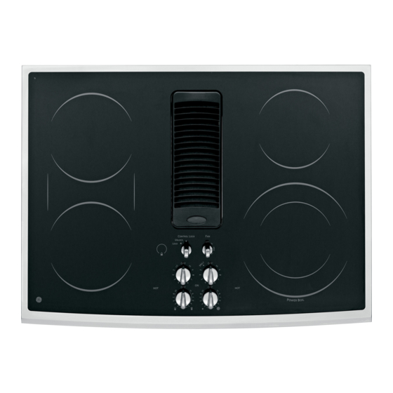
Page 4: Dual Surface Unit
Features of Your Cooktop. Throughout this manual, features and appearance may vary from your model. CO_TRO, took ® Feuture Index (Features and appearance may vary) 0 Left Rear Surface Unit Bridge Surface Unit Left Front Surface Unit Vent Grille Vent Filter (below the vent grille) Right Rear Surface Unit Dual Surface Unit 0 Model and Serial Number Label lunder... - Page 5 Using the surface units, GEApplionces.c Radiant Surface Units The control for the radiant surface unit can The surface unit ON indicator light will glow be set anywhere between LO and HI for an when any surface unit is on. unlimited number of heat settings. With the The HOT surface indicator light will glow when infinite switch the coil cycles on and off to the glass surface is hot and will remain on until...
-
Page 6: Surface Units
Using the surface units, Dual Surface Unit & To use the small (6-inch)surface unit, turn the The right front surface unit has 2 cooking sizes to select from so you can match the size of the knob counterclockwise to D and select the unit to the size of the cookware you are using. - Page 7 Selecting types of cookwure ngode]s. (onnon-induction models) GEAppliances.com The following information will help you choose cookware which will give good performance on glass cooktops. See insert for cookware to use with induction cooktops. Stainless Steel: Porcelain Enamel on Cast Iron: recommended recommended if bottom of pan is coated...
-
Page 8: Care And Cleaning
Care and cleaning of the cooktop. Be sure electrical power is off and all surfaces are cool before cleaning any part of the cooktop. How to Remove Protective Shipping Film and Packaging Tape Carefully grasp a corner of the protective To assure no damage is done to the finish shipping film with your fingers and slowly peel of the product, the safest way to remove... -
Page 9: Glass Cooktop
Cleaning the glass cooktop. GEAppliances.c Normal Daily Use Cleaning ONLYuse CERANABRY1-E ®Ceramic Cooktop Shakethe cleaning cream well. Cleaner on the glass cooktop. Other creams Apply a few drops of CERAIVlA may not be as effective. BRYTE ® Ceramic Cooktop Cleaner directly to the cooktop. -
Page 10: Glass Cooktop
Cleaning the glass cooktop. Metal Marks and Scratches Be careful not to slide pots and pans if pots with a thin overlay of aluminum across your cooktop. It will leave metal or copper are allowed markings on the cooktop surface. to boil dry, the overlay may leave black discoloration on the cooktop. - Page 11 Radiant str cti Downdraft Cooktop I If you have questions, call 800.GE.CARES (800.432.2737) or visit our Website at: GEAppliances.com BEFORE YOU BEGIN SAFETY INSTRUCTIONS IMPORTANT Read these instructions completely and carefully. WARNING - TOREDUCETHE RISK .IMPORTANT - Save these...
-
Page 12: Installation Instructions
Installation Instructions UNPACKING YOUR COOKTOP PARTS INCLUDED (PACKED BELOW THE COOKTOPI Blower assembly (9) Sheet metal screws , Vent filter Blower plenum (8-18 x 3/8") , Cleaning cream (4) Nuts (10-32 keps - nuts with Foam gasket tape (9 ft. roll) , Scrub sponge or scraper lock washers attached) , Vent grille... -
Page 13: Ductwork
Installation Instructions PREPARATION TOOLS AND MATERIALS ELECTRICAL REQUIREMENTS YOU WILL NEED This appliance must be supplied with the proper voltage and frequency, as listed in these Installation Instructions, and connected to an individual, properly grounded branch Flat-blade screwdriver circuit, protected by a 40-amp circuit breaker or time delay Electrician's pliers fuses. - Page 14 Installation Instructions CABINET PREPARATION PREPARING THE BASE CABINET l_l PREPARING FOR INSTALLATION Positioning the cooktop This cooktop is designed to fit easily into a variety of cabinets. However, some cabinets may require Thecooktopisdesigned to lookbestwhencenteredin a modifications. cabinetat least30"wide. Preparing a cabinet that is against a wall The exhaust vent beneath the cooktop must be located In some cabinets, the sides may need to be scooped or cut between wall studs or floor joists so that the ductwork may...
- Page 15 Installation Instructions CABINET PREPARATION CUTOUTS ITI PREPARING THE COUNTERTOP Fs] PREPARING FOR DUCTWORK NOTE:Ductwork MUSTbe vented to outside. DO NOT vent The countertop must have a deep flat surface to accommodate the cooktop and the vent. into a wall, ceiling, crawlspace, attic or any concealed Countertops with a rolled front edge and space.
- Page 16 Installation Instructions DUCTWORK CALCULATIONS Equivalent Number Equivalent Duct Pieces Length* x Used - Length Calculate Total Equivalent Ductwork Length 5" round Equivalent Number Equivalent to3½" x i0" Duct Pieces Length* x Used - Length 90° elbow 37 ft. 5" round transition 6"...
- Page 17 Installation Instructions EXHAUST BLOWER RATINGS EXHAUST BLOWER SAFETY WARNING Sufficient air is needed for proper combustion and exhausting of gases through the flue (chimney) of other fuel burning equipment to prevent back drafting. Follow the heating equipment manufacturer's guidelines and safety standards such as those published by the National Fire Protection Association (NFPA),the American Society for Heating, Refrigeration and Air Conditioning Engineers (ASHRAE) a nd local code authorities.
- Page 18 Installation Instructions DUCTWORK INSTALLATION (Note: For planning purposes only.) 171INSTALLING THE DUCTWORK OPTIONAL INSTALLATION: REAR WALL VENTING Use galvanized or aluminum duct in 6" round or 3VJ' x 10" size, or a combination of both. 5" round duct may be used on SHORT DUCT runs, but best results will be obtained using 31/4' ' x 10"...
-
Page 19: Installing The Gasket
Installation Instructions UNPACKING THE COOKTOP/INSTALLING THE GASKET I_ INSTALLING THE FOAM GASKET Foam Gasket Installation Notes: Do not install the cooktop into the countertop ,The foam gasket tape should be installed within without installing the foam gasket as shown. 1/8" of the edge of the glass. Do not stretch or It protects the bottom edge of the glass from the twist the foam gasket tape. - Page 20 Installation Instructions INSTALLING THE COOKTOP INSTALLING THE COOKTOP CHECKING FOR FLATNESS Inspect the cooktop gloss for rocking or uneven , CAUTION: gap on oil four sides at the countertop surface. Do not attempt to force the gloss to meet DO NOT LIFT the countertop.
- Page 21 Installation Instructions INSTALLING THE COOKTOP INSTALLING THE BLOWER PLENUH INSTALLING THE BLOWER TO THE COOKTOP TO THE PLENUM Slide the plenum, with the blower opening on the Orient the blower discharge opening to match the left, into the opening in the bottom of the cooktop. ductwork in Steps 6 and 7.
- Page 22 Installation Instructions INSTALLING THE COOKTOP ATTACHING A BLOWER BLOWER ELECTRICAL TRANSITION DUCT CONNECTIONS {cont.} Use a blower transition duct for all downward , Connect the g-pin plug on the blower assembly to duct installations to connect to 6" round standard the matching g-pin receptacle on the bottom of the...
-
Page 23: Electricalconnections
Feed the leads through the hole in the wire ELECTRICAL REQUIREMENTS* compartment. Model # Voltage Frequency As local codes permit purchase PP989 120/240V 60Hz 9.1KW a listed conduit 120/208V 60Hz 6.9KW _'_'_ connector suitable *For reference only. Verify with product rating plate. - Page 24 Installation Instructions ELECTRICALCONNECTIONS MAKING ELECTRICAL CONNECTIONS JTY]MAKING ELECTRICAL CONNECTIONS (cont.) Effective January 1, 1996, the National Electrical Code requires that new, but not Three-conductor brunch circuit connection existing, construction utilize a four-conductor .When installing in existing construction built connection to an electric range. When installing prior to January 1, 1996, and if permitted an electric range in new construction,...
-
Page 25: Final Assembly
Installation Instructions FINAL ASSEMBLY INSTALL DOWNDRAFT FILTER AND VENT GRILLE Do not operate the vent without the filter in place. Place the filter diagonally through the vent opening. Filter Vent -Chamber Plake sure it rests, at an angle, on the supports in the vent opening. -
Page 26: Troubleshooting Tips
Before you call for service... Troubleshooting Tips--Save time and money! Review this chart first and you may not need to call for service. Possible Causes What To Do Water won't boil , Cover pan with a lid. , Turn the downdraft fan OFFuntil the water begins to boil. Surface units will not Improper cookware , Pan bottoms should be flat, fairly heavyweight and... - Page 27 Notes. GEAppliances.com...
- Page 28 Notes.
- Page 29 GE Electric Cooktop Warranty. All warranty service provided by our Factory Service Staple your receipt here. Centers, or an authorized Customer Care ®technician. Proof of the original purchase To schedule service, on-line, visit us at GEAppliances.com, date is needed to obtain service or coil 800.GE.CARES (800.432.2737).
-
Page 30: Consumer Support
Contact Us GEAppliances.com If you are not satisfied with the service you receive from GE,contact us on our Website with all the details including your phone number, or write to: General Manager, Customer Relations GEAppliances,Appliance Park Louisville,KY/40225 Register Your Appliance GEAppliances.com... - Page 31 GEAppliances.com Instrucciones de seguridad ..2-3 Instrucciones de operaci6n Caracteristicas de su estufa ....Ideas sabre las piezas de cocina ... PP989 Limitactor de temperatura ....Quemaclor de puente ...... Sistema de ventilaci6n de la estufa ..Uniclacles de superficie ....
- Page 32 INSTRUCCIONES DE SEGURIDAD IMPORTANTES. LEA TODAS LAS INSTRUCCIONES ANTES DE USAR. JAADVERTENCIA ] Lea todas las instrucciones de seguridad antes de utilizar este producto. No seguir estas instrucciones puedegenerar un incendio, una descarga el6ctrica, lesiones corporales o la muerte. IA ADVERTENClA j lNSTRUCCIONES GENERALES DE SEGURIDAD No utilice toallas u otras telas gruesas en lugar de una Use este aparato s61ocon el objetivo para el que fue creado,como se describe en este Manual del...
-
Page 33: Instrucciones De Seguridad
INSTRUCCIONES DE SEGURIDAD IMPORTANTES. LEA TODAS LAS INSTRUCCIONES ANTES DE USAR. GEAppliances.com JA ADVERTENCIA I EN CASO DE INCENDIO, SIGA LOS SIGUIENTES PASOS PARA EVITAR LA PROPAGACION DEL FUEGO: No utilice agua en incendios de grasa. Nunca levante ajuste bien, una plancha para galletas o una bandeja unasart6n en llamas. -
Page 34: Caracteristicas De Su Estufa
Caracteristicas de su estufa. A travds de este manual, las caracteristicas y la apariencia podfian variar de acuerdo con su model®. Indite de caracteristicas (las caractefisticas y la apariencia podfian variar de acuerdo con su model®) 0 Unidad de superficie posterior izquierda 0 Unidad de superficie de puente O Unidad de superficie frontal izquierda CONTROL... -
Page 35: Botones De Control
C6mo usar las unidades de superficie. Unidades de superficie radiantes :ill:i( Zi!l! i!Z%i ¸ )L! /L4( : Elcontrolde la unidadde superficie radiante La luzindicadorade la unidadde superficiebrillar6 puedecolocarse en cualquierlugar entreLO(Bajo) cuandocualquierade lasunidadesde superficie est6nencendidas ON(Encendido). y HI (Alto) p ara un n0merode selecciones de IIII iii! II i I II II Iiiiiii calentamiento ilimitado.Conel interruptorinfinitoel Elluz indicadora de HOTSURFACE (Superficie... - Page 36 C6mo usar los unidades de superficie. Unidad de superficie dob/e La unidad de superficie frontal derecha tiene Para usar la unidad de super_iciepequeha (6"), dos tamahos para cocinar entre los que usted gire el bot6n en direcci6n contraria alas agujas puede escogery ad podrd combinar el tamaho del reloj Dy seleccione el ajuste deseado.
-
Page 37: Estufa De Vidrio
Elecci6n d elostiposderecipientes decocci6n puramoddos deestufa devidfio. GEAppliances.com La siguiente informaci6n Io ayudard a elegir los recipientes de cocci6n que brindan un buen desempeho en estufas de vidrio. Ver el folleto sabre recipientes para usar con estufas de inducci6n. Acero inoxidable: Vidrio-Cer_micu: Recomendadas Otiles, pero no son recomendadas... - Page 38 Cuidado y limpieza de la estufa. Cercidrese de que el suministro eldctrico estd suspendido y que todas las superficies estdn ffias antes de limpiar cualquier parte de la estufa. C6mo quitar el envoltorio de protecci6n y la cinta de embalaje Con cuidado tome una punta del envoltorio de protecci6n Para asegurarse de no da_ar el acabado del producto, con sus dedos y lentamente qu[telo de la superficie...
- Page 39 C6mo limpiar la estufa de vidrio. GEAppliances.c Limpieza de uso normal diario SOLAMENTE use limpiador de estufas de Use una toalla de papel o una almohadilla cerc_mica CERAMABRYTE ® en su estufa de de limpiar estufas de cerc_micaCERAMA vidrio. Otras cremas podr[an no ser efectivas. BRYTE ®...
- Page 40 C6mo limpiar el vidrio de la estufa. Marcas met61icas y rasgufladuras Estas deberfan removerse inmediatamente Tenga cuidado de no deslizar ollas o antes de calentar la estufa de nuevo sartenes a trav6s de su estufa. Elias o la decoloraci6n se convertirc_ en dejar@n marcas sobre la superficie de decoloraciones permanentes.
- Page 41 Instrucciones Estufaradiante de deinstalaci6 ventilaci6n descendente I Si tiene alguna pregunta, Ilame al 800.GE.CARES (800.432.2737)o visite nuestro sitio en la Web: GEAppliances.com INSTRUCCIONES IMPORTANTES DE ANTES DE COMENZAR SEGURIDAD Lea estas instrucciones completa cuidadosamente. ADVERTENCIA - PARA REDUCIR EL .IMPORTANTE - Guarde estas...
-
Page 42: Rejilla De Ventilaci6N
Instrucciones d e instalaci6n DESEMPACANDO SU ESTUFA PARTES INCLUIDAS (EMPACADAS DEBAJO DE LA ESTUFA) Filtro del ventilador Tornillos de plancha , Ensambladura del soplador met61ica (9)(8-18 x 3/8'1 , C6mara del soplador , Crema de limpieza Cinta de junta de espuma (folio , Tuercas (4)(10-32 tuercas - Esponja de restriegue de 9 pies) - Page 43 Instrucciones d e instalaci6n PREPARACI6N HERRAMIENTAS QUE NECESITAR/_ REQUISITOS ELI_CTRICOS Sierra Esteelectrodom@sticodebe suplirse con el voltaje y la frecuencia apropiados, conforme se indica en estas Destornillador piano Instrucciones de Instalaci6n,y debe set conectado a un ramo Alicates de electricista el@ctricoconectado apropiadamente a tierra, protegido Cinta adhesiva de conductos pot un interruptor de circuito de 40 amperios o fusibles de dilataci6n de tiempo.
- Page 44 Instrucciones d e instalaci6n PREPARACION DEL GABINETE PREPARACI6N DEL GABINETE DE LA m PREPARACI6N PARA LA INSTALACI6N BASE Posici6n de su estufa Laestufa est6diseflada paralucirmejorcuandoest6centrada Estaestufa est6 diseflada para ajustarf@ilmente en una variedadde gabinetes.Sinembargo,algunosgabinetespodrian enungabinete deporIomenos B0"deancho. requerirmodificaciones. Laventanilla deescape debajo delaestufadebeestar Iocalizada e ntrelosbajantes dela paredo entrelasvigasdel Preparando un gabinete que ajuste contra la pared pisodeformaqueeltrabajodetubospuedaserinstalado...
- Page 45 Instrucciones d e instalaci6n CORTES DE PREPARACION DEL GABINETE r_ PREPARANDO LA ENCIMERA r_] PREPARACIONES PARALOSCONDUCTOS La encimera debe tener una superficie plana NOTA: E ltmbajo de conductosDEBE tener ventilaci6nhaciael profunda para acomodar la estufa y la exterior. NOVENTILE h acialas paredes, t echo,esquinas, 6 ticoso ventilaci6n.
- Page 46 Instrucciones d e instalaci6n CALCULOS DE LOS CONDUCTOS Longitud NOmero Longitud Piezas de conducto equivalente* x usado = equivalente Colcule Io Iongitud de conducto equivolente totol Redondode Longitud N6mero Longitud 5"atransici6n Piezas de conducto equivalente* x usado equivalente de 3¼"x 10" Redondos Codo de 90°...
- Page 47 Instrucciones d e instalaci6n RANGOS DEL SOPLADOR DE ESCAPE ADVERTENCIA DE SEGURIDAD DEL SOPLADOR DE ESCAPE Suficienteaire es necesariopara una combusti6napropiaday para deshacersede los gasesa trav@s de una salidade humo (chimenea) de equiposque quemancombustiblespara prevenirretroalimentaci6n.Sigalas recomendacionesdelfabricante del equipode calentamientoy losest6ndaresde seguridadtales como los publicadospor la Asociaci6nnacionalde protecci6nde incendios(NFPA), y la Sociedadamericana de ingenieros de calefacci6n,acondicionadoresde aire y refrigeraci6n(ASHRAE), y los c6digosde las autoridadeslocales.
- Page 48 Instrucciones d e instalaci6n INSTALACI6N DE LOS CONDUCTOS (Nota: Solamente con el prop6sito de planificaci6n.) INSTALACI6N OPCIONAL: VENTILACI6N E] c6Flo INSTALAR LOS CONDUCTOS POR LA PARED POSTERIOR Use conductos de aluminio o galvanizados en 6" o 3½"x 10" en tama_o, o una combinaci6n Para corrientes de CONDUCTO CORTO se puede...
- Page 49 Instrucciones d e instalaci6n COMO DESEMPACAR LA ESTUFA/ INSTALAR LA JUNTA D C6MO INSTALAR LA JUNTA DE Notas sobre la instalaci6n de la junta ESPUHA de espuma: No instale la estufa en la encimera , La cinta dejunta de espuma deberia ser instalada haber instalado la junta de espuma como se dentro de :]_/8"...
-
Page 50: Ld C6Mo Instalar La Estufa
Instrucciones d e instalaci6n C6MO INSTALAR LA ESTUFA E_] C6MO INSTALAR LA ESTUFA C6MO INSPECCIONAR LO PLANO Inspeccione el vidrio de la estufa en busca de rocas o brechas con protuberancias en todos los lados de la superficie de la encimera. No intente PRECAUCION: forzar el vidrio a moldearse a la encimera. - Page 51 Instrucciones d e instalaci6n C6MO INSTALAR LA ESTUFA F_lC6MO C6MO INSTALAR LA C/_MARA DEL INSTALAR LA C/_MARA DEL SOPLADOR DE LA ESTUFA SOPLADOR Deslicela c6mara con la abertura del sopladordel lado Oriente la abertura de descarga del soplador izquierdo en la abertura en el fondo de la estufa Empuje hasta que iguale el conducto en los Pasos 6 y 7 Deslice las cuatro tachuelas...
- Page 52 Instrucciones d e instalaci6n COMO PEGAR UNA TRANSICION DE SOPLADOR C6MO PEGAR UNA TRANSlCION CONE×IONES ELI_CTRICAS SOPLADOR DEL SOPLADOR (cont.) Use un conducto de transici6n de soplador para Conecte el tap6n de 5 pasadores en la todas las instalaciones de conductos de flujo de aire ensambladura para combinar...
-
Page 53: Conexiones El6Ctricas
Alimente losconductores REQUISITOS ELI_CTRICOS* a tray,sdelagujero en # Modelo Voltaje Frecuencia elcompartimiento d e alambre. PP989 120/240V 60Hz 9.1KW Conforme Iopermitan 120/208V 60Hz 6.9KW losc6digos locales, *Para referencia solamente. Verifique con la plato de compre unconectador especificaci6n del producto. - Page 54 Instrucciones d e instalaci6n CONE×IONES ELI CTRICAS c61vlo HACER LAS CONE×JONES C6PIO HACER LAS CONEXIONES ELECTRICAS ELi_CTRICAS (cont.) Conexi6n de ramal de circuito de tres Efectivo el i de enero de 1996, el National Electrical conductores Code requiere las construcciones nuevas, pero no ya existentes, utilicen conexiones de cuatro conductores .Cuando se encuentre...
- Page 55 Instrucciones d e instalaci6n ENSAMBLAJE FINAL COMO INSTALAR EL FILTRO DE FLUJO DOWNDRAFT Y LA PARRILLA VENTILACION No opere la ventilaci6n sin el filtro en su lugar. , Coloque el filtro diGgonGImente a trav6s de la abertura de ventilaci6n. Filtro de ventilaci6n Cdmara de - ventilaci6n...
- Page 56 Antes de llamar para solicitar servicio... primero y Ideas sabrela identificaci6ny soluci6n de problemas - iAhorre tiempo y dinero! Reviseesta tabla es posiblequa no necesite Ilamamos en busca de servicio. Causas posibles Qu6 hacer El agua no hierve , Cubra la sart6n con una tapa. Apague el ventilador (Posici6n OFF)hasta que el agua comience a hervir.
- Page 57 Causas posiNes Qu6 hacer Picadura (a hendidura) Hezda de az_car caliente, Llame a un t6cnico calificado para su reemplazo. de la cocina derramada o pl_stico derretido en la cocina. La cocina emite La cocina est6 bloqueada., AsegL_resede que el Selector de Control de Bloqueo (Control un sonido que se puede Lock Selector) est6 en UNLOCK(Desbloqueo).
- Page 58 Notas.
- Page 59 GE,podria tener que hacerse cargo de los costes de envfo o bien podria solicitdrsele que Ileve el producto a una centro de servicio de GE autorizado para realizar la reparaci6n. En Alaska, la gamntia excluye el costo de envio o los visitas de servicio a su casa.
-
Page 60: Apoyo Al Consumidor
Solicite una reparaci6n GEAppliances.com El servicio de expertos GE est_ a tan s61oun paso de su puerta, iEntre en I[neay solicite so reparaci6n cuando le venga bien cualquier d[a del aho! O Ilame a1800.GE.CARES (800.432.2737)durante horas normales de oficina. Real L ife Design Studio (Estudio d ediseho paralavidareal) GEAppliances.corn GEapoya el concepto de Dise_o Universal-productos, servicios y ambientes que pueden usar gente de todas las edades, tama_os y capacidades.