Jet JSG-96 Operating Instructions And Parts Manual
Benchtop disc/belt sander
Hide thumbs
Also See for JSG-96:
- Operating instructions manual (29 pages) ,
- Operating instructions and parts manual (24 pages) ,
- Operating instructions manual (20 pages)
Table of Contents
Advertisement
Quick Links
This .pdf document is bookmarked
Operating Instructions and Parts Manual
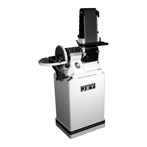
Benchtop Disc/Belt Sander
Model JSG-96
(shown with optional closed stand 708597)
WALTER MEIER (Manufacturing) Inc.
427 New Sanford Road
LaVergne, Tennessee 37086
Part No. M-708595
Ph.: 800-274-6848
Revision G3 08/2011
www.waltermeier.com
Copyright © 2011 Walter Meier (Manufacturing) Inc.
Advertisement
Table of Contents

Related Manuals for Jet JSG-96


Summary of Contents for Jet JSG-96
- Page 1 This .pdf document is bookmarked Operating Instructions and Parts Manual Benchtop Disc/Belt Sander Model JSG-96 (shown with optional closed stand 708597) WALTER MEIER (Manufacturing) Inc. 427 New Sanford Road LaVergne, Tennessee 37086 Part No. M-708595 Ph.: 800-274-6848 Revision G3 08/2011 www.waltermeier.com...
-
Page 2: Warranty And Service
Walter Meier is consistently adding new products to the line. For complete, up-to-date product information, check with your local Walter Meier distributor, or visit waltermeier.com. WARRANTY JET products carry a limited warranty which varies in duration based upon the product (MW = Metalworking, WW = Woodworking). WHAT IS COVERED? This warranty covers any defects in workmanship or materials subject to the exceptions stated below. -
Page 3: Table Of Contents
Table of Contents Warranty and Service.......................... 2 Table of Contents ..........................3 Warning ............................. 4 Grounding Instructions ........................6 Introduction ............................7 Specifications ............................. 7 Unpacking ............................8 Assembly ............................8 Open Stand Assembly (Optional)......................8 Closed Stand Assembly (Optional) ....................9 Sander Assembly ..........................9 Adjustments ............................. -
Page 4: Warning
Warning Wear eye protection. Always keep guards in place and in proper operating condition. Do not operate the machine without the guards for any reason. This disc/belt sander is intended to be used with wood and wood products only. Use of this disc/belt sander and a dust collector with metal products is a potential fire hazard. - Page 5 • USE RECOMMENDED ACCESSORIES. The use of accessories and attachments not recommended by JET may cause hazards or risk of injury to persons. • NEVER STAND ON A MACHINE. Serious injury could occur if the machine is tipped.
-
Page 6: Grounding Instructions
Grounding Instructions Electrical connections must be made by a qualified electrician in compliance with all relevant codes. This machine must be properly grounded to help prevent electrical shock and possible fatal injury. In the event of a malfunction or breakdown, grounding provides a path of least resistance for electric current to reduce the risk of electric shock. -
Page 7: Introduction
Introduction This manual is provided by Walter Meier (Manufacturing) Inc., covering the safe operation and maintenance procedures for a JET Model JSG-96 Disc/Belt Sander. This manual contains instructions on installation, safety precautions, general operating procedures, maintenance instructions and parts breakdown. This machine has been designed and constructed to provide years of trouble free operation if used in accordance with instructions set forth in this manual. -
Page 8: Unpacking
Unpacking Open shipping container and check for shipping damage. Report any damage immediately to your distributor and shipping agent. Do not discard any shipping material until the Sander is assembled and running properly. Compare the contents of your container with the following parts list to make sure all parts are intact. -
Page 9: Closed Stand Assembly (Optional)
Figure 1 machine. 1. Move the sander to a workbench or one of JET’s optional stands. Bolt the unit firmly to hold in place. JET’s closed stand uses four 3/8”x3” hex cap bolts, four 3/8” lock washers, eight 3/8”... -
Page 10: Adjustments
Adjustments Sanding Belt Table Adjustment Always disconnect sander from the power source before servicing or making any adjustments. Failure to comply may cause serious injury. 1. Place a square on the sanding belt table with one edge along the graphite pad, or sanding belt (Figure 4). -
Page 11: Horizontal Sanding Workstop
Horizontal Sanding Workstop 1. Loosen the socket head cap screw (A, Fig. 7) so that the sanding belt can be rotated to the horizontal position. 2. Rotate the sander until the stop (B, Fig. 7) contacts the sander base. Tighten the socket head cap screw. -
Page 12: Belt Tracking Adjustment
Belt Tracking Adjustment 1. Connect the machine to the power source. One time quickly turn the machine “ON” and “OFF”. This will allow you to view the belt’s tendency to run down the middle, to the right, or to the left. The belt should run centered on the sanding drums. -
Page 13: Sanding Disc Replacement
4. If the miter slot is not parallel, loosen the two socket head cap screws (A, Fig. 13) and adjust for parallel. Tighten the two screws when the adjustment is complete. 5. Always maintain a gap of approximately 1/16” between the table edge and disc. Once the table is square and parallel to the disc adjust the 90°... -
Page 14: Dust Collection
1. Hook the sander to a dust collector using a 4” diameter hose and clamp (A, Fig. 16). JET offers a wide variety of hoses, adapters and dust collectors. 2. Loosen the wing nut (B, Fig. 16) and pull the gate (C, Fig. -
Page 15: Troubleshooting
Troubleshooting Trouble Probable Cause Remedy Sander unplugged from wall, or Check all plug connections. motor. Replace fuse, or reset circuit breaker. Sander will not start Fuse blown, or circuit breaker tripped. Make sure supply circuit matches amperage rating on motor plate. Cord damaged. -
Page 16: Disc Sander Assembly Breakdown
Disc Sander Assembly Breakdown... -
Page 17: Parts List For The Disc Sander Assembly
Parts List for the Disc Sander Assembly Index No. Part No. Description Size 1 ....JSG96-101A....Base ....................1 2 ....JSG96-102 ....Motor ....................1 ....JSG96-102A....Starting Capacitor (not shown)......150MFD, 125VAC..1 ....JSG96-102B....Running Capacitor (not shown)......20uF, 250VAC .... 1 3 ....TS-1550041 ....Flat Washer............M6 ......4 4 .... - Page 18 Index No. Part No. Description Size 53 .... JSG96-153 ....Bushing....................1 54 .... JSG96-154 ....I.D. Label ................... 1 55 .... JSG96-155 ....Indication Label .................. 1 56 .... JSG96-156 ....Pin ..................... 1 57 .... JSG96-157 ....Tap Screw............1/4”×3/8” ....7 58 .... JSG96-158 ....Holder-Small (Running Capacitor)............1 59 ....
-
Page 19: Belt Sander Assembly Breakdown
Belt Sander Assembly Breakdown See Disc Sander Breakdown... -
Page 20: Parts List For The Belt Sander Assembly
Parts List for the Belt Sander Assembly Index No. Part No. Description Size 1 ....JSG96-201 ....Bracket ....................1 2 ....TS-0208071 ....Hex Socket Cap Screw ........5/16x1-1/4 ....1 3 ....JSG96-203 ....Pin ..................... 1 4 ....JSG96-204 ....Fixed Plate ..................1 5 .... - Page 21 Index No. Part No. Description Size 56 .... JSG96-256 ....Lock Handle* ............5/16x1-1/4 ....2 57 .... JSG96-257 ....Graphite Pad ..................1 58 .... JSG96-155 ....Indication Label .................. 1 59 .... JSG96-259 ....Loosen/Tighten Label................1 60 .... JSG96-260 ....Flat Washer............1/4x9/16x1/8 ....2 61 ....
-
Page 22: Open Stand Assembly (Optional)
Open Stand Assembly (Optional) Long "Stand Top" overlaps Short "Stand Top" Index No. Part No. Description Size 1 ....JSG96-401 ....Stand Top (front and rear, short) ............2 2 ....JSG96-402 ....Stand Top (left and right, long)............. 2 3 ....JSG96-403 ....Stand Leg w/Tool Holder ..............2 4 .... -
Page 23: Closed Stand Assembly (Optional)
Closed Stand Assembly (Optional) -
Page 24: Parts List For Closed Stand (Optional)
14 .... JSG96-314 ....Tool Shelf................... 1 15 .... TS-0060031 ....Hex Head Screw* ..........3/8x3/4....... 1 16 .... JSG96-316 ....Washer* ............3/8x1-1/8 ....1 17 .... JSG96-317 ....JET Plaque ..................1 18 .... JSG96-318 ....Door ....................1 19 .... JSG96-319 ....Latch ....................1 20 ....
Need help?
Do you have a question about the JSG-96 and is the answer not in the manual?
Questions and answers