GReddy Turbo Kit Installation Manual
Honda s2000 ap1 (2000-2003 f20c) t518z 8cm2
Hide thumbs
Also See for Turbo Kit:
- Installation manual (23 pages) ,
- Installation manual (16 pages) ,
- Installation manual (21 pages)
Advertisement
Quick Links
Advertisement

Related Manuals for GReddy Turbo Kit


Summary of Contents for GReddy Turbo Kit
- Page 1 GReddy Turbo Kit HONDA S2000 AP1 (2000-2003 F20C) T518Z 8cm...
- Page 2 Premium grade gasoline (91 octane or higher) is required with this Kit. • Make sure that the vehicle is not equipped with any ECM upgrade chips. • Use of GReddy Racing Spark Plugs ISO #8 or NGK plugs (colder than factory) is recommended with this kit. Important •...
- Page 3 For Block side Center Union For Filter side Side Union O ring For attachment O ring For Center Union O ring For Side Union Oil Line Hose Plug Union plug bolt O ring attachment Corrugated Tube GReddy Oil Filter Stay...
- Page 4 34 Oil Pressure Hose Union fitting Union fitting Union fitting 3 Way Fitting Copper Washer 40 Oil Return Flange Tube Hose Union Copper Washer 43 Vacuum Hose (Actuator, Pressure sensor, Air solenoid) 44 Rubber Hose (Water Line) (Blow-by) (Oil return) (Air-pump) 48 Silicone Hose Reducer...
- Page 5 66 Bracket Intercooler Air pump Vacuum Tank Air Diversion Panel *No longer used in this kit* Pressure Sensor 72 Pressure Sensor Adapter 73 Hose Union Hose Union 75 Rubber Mount 76 Clip 77 Air Duct 78 Thermo Cloth 79 Zip Tie Black 80 Zip Tie Black...
-
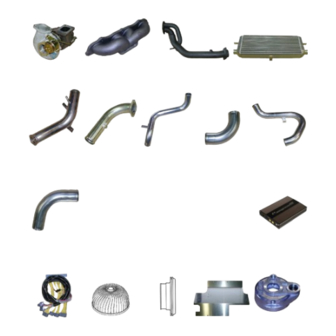
Page 6: Parts List
Parts List 1 2 3 4 5 6 7 8 9 10 11 12 13... - Page 7 21 22 23 24 27, 28 25 26 40 35, 36 41 42 43 44-47 48-50...
- Page 8 51, 52 53-59 No longer in use 79, 80 81-92...
- Page 9 2. Removal of Stock Parts When removing the stock parts, make sure you read over the factory repair manual for the proper procedures 2-1 Disconnect the battery. Write down the radio presets and be sure to have the code for the factory radio. 2-2 Relieve the fuel pressure in the fuel system.
-
Page 10: Kit Installation
3. Kit Installation 3-1 Turbo Installation Before installing the turbo charger, make sure to insulate the surrounding components with the provided thermo cloth. Since the area around the exhaust manifold will get very hot, it is important to insulate the surrounding components to prevent fire/heat damage. - Page 11 3-2 Oil Pressure Switch Remove the factory oil pressure switch. Install #36 union into the #38 three way fitting. Proceed to install into the block where the oil pressure switch was located. *Be sure to use Teflon tape on each side of the union.
- Page 12 Install #29 union plugs in the 2 locations in adapter #20 as shown. Install union #22 with O ring #25 and union #23 with O ring #26 in the adapter as shown. Install plug bolt #30 as shown. Lubricate the o-ring and the thread to prevent any cross threading and damaging the o-ring.
- Page 13 Connect oil hoses #27 (A) & #28 (B). Oil line hose A goes between the center unions. Where the 90 degree fitting is on the filter side, and the 45 degree fitting on the engine side. Oil line hose B goes between the side unions. Where the 45 degree fittings are on each side.
- Page 14 3-4 Oil Feed Line installation Install the #34 oil feed line as shown, connecting one end to the fitting from the oil pressure switch and the other to the union on the top side of the turbo. Bend the line to make room for the compression pipe on the turbo.
- Page 15 Install the downpipe to the turbine housing using #61 turbine gasket, secure with provided nuts and lock washers. Use factory spring bolts to attach the downpipe to the catalytic converter. Parts used: 61 Use the factory exhaust manifold bracket to support the downpipe.
- Page 16 (3) Remove the secondary air control solenoid valve hoses from the hard lines and take note which hose goes to which hard line. Attach the secondary air control solenoid valve to the provided bracket #68 using the provided M5 nut/bolt #82, then install the bracket onto the chassis cross bar using the OEM bolt.
- Page 17 3-7 Intercooler Installation Attach bracket #66 to the radiator support as shown using the existing hole and the provided hardware #89. Longer side of the bracket attaches to the radiator support. Parts used: 66 89 Intercooler mounting. Left and Right Mounting Brackets Use the existing hole on the underside of the frame as shown for the intercooler mounting brackets.
- Page 18 3-8 Air Pump Relocation (1) Remove the lower mounting bolt from the air pump, place the #67 bracket as shown. Use the factory bolt in the same location it was taken to secure the bracket down. Use the provided #89 nuts and bolts to relocate the pump towards the front of the car, mounting it to the end of the #67 mounting bracket as shown.
- Page 19 Install suction pipe S-1 to the compressor housing using the provided #62 gasket. Be sure that the bracket on the pipe is positioned onto the rubber vibration mount previously installed. Secure S-1 at the compressor housing with the provided #90 hardware.
- Page 20 3-10 Intercooler Piping Install #75 rubber vibration mount to the factory hole on the chassis as shown. Parts used: 75 Install hose fitting #73 to compression pipe C-1. Be sure to use Teflon tape on the threads of the hose fitting. Parts used: 6,73 Cut provided vacuum hose to 200mm and route it between the actuator and C-1 and secure the...
- Page 21 Install the Compression tubes C-4, C-5 from intercooler outlet to the throttle body as shown. Compression Tube C- C- C-4 4 4 4 C- Secure the bracket to the air pump bracket with the provided nut/bolt #89. Compression Tube C- C-5...
- Page 22 3-11 Airinx Installation Remove the top bolt on the Airinx kit, remove the outer frame, then the filter. Install the rubber hose adapter to the base of the Airinx kit. Parts used: 16 17 Reassemble the Airinx filter, hand tighten the top bolt.
- Page 23 3- - - - 13 Injector Installation Apply a light amount of silicon grease to the O rings on each injector. The smaller O ring at the top and the two larger O rings at the base. Parts used: Remove the factory fuel rail. Be careful when removing the fuel pulsation dampener and the fuel pressure regulator.
- Page 24 Use the provided spacers under the brackets marked A in the image (use on the intake manifold side). Use the provided extended bolt in place of the factory bolt to accommodate for the added length. Parts used: A 3- - - - 14 Factory Pressure Sensor Relocation Remove the factory pressure sensor and replace it with the provided pressure sensor adapter.
- Page 25 3-15 Walbro Fuel Pump Installation Remove the factory spare tire from the trunk. Remove the holding tray located behind the seats. Remove the pushpins securing the tray. After removing the pushpins, slide the tray out through the trunk. Remove the fuel pump cover secured by 3 screws.
- Page 26 (1) Remove the OEM air Diversion Panel. Position and route the intake ducting #77 as shown. Use the provided zip ties to secure the ducting onto the GReddy air diversion panel, and at the rear of the intercooler. Parts used: 77...
- Page 27 3-17 Bumper and Under-Cover Modification (1) The factory under-covers and fender liners need to be cut in order to accommodate the intercooler piping. Cut the areas as shown. Front engine undercover Rear engine undercover Passenger side fender liner Driver side fender liner (2) Cut the factory front bumper as shown to accommodate the front mount intercooler.
- Page 28 3-17 e-Manage Ultimate Installation Remove the driver side kick panel cover in order to access the ECU and ECU harness. Disconnect the ECU harness from the ECU. Connect the Emanage Ultimate Plug and Play Harness to the ECU and plug the stock ECU harness into the Ultimate Plug and Play Harness.
- Page 29 • It is very important that you monitor the boost pressure, and make sure not to over boost. Over boosting can cause engine damage. • GReddy Performance Products, Inc. is not responsible for any engine damage caused by over boosting (increased boost), modification to the kit, and/or misuse of the product. NO WARRANTY is offered.
- Page 30 Products, Inc. recommends the use of 100% FULLY Synthetic Motor Oil made for turbochargers! The use of improper oils may cause damage and shorten the life of the turbocharger. GReddy Performance Products, Inc. will not be held responsible for damages due to the use of improper oil.
Need help?
Do you have a question about the Turbo Kit and is the answer not in the manual?
Questions and answers