
Related Manuals for GReddy Turbo Kit Emanage Ultimate


Summary of Contents for GReddy Turbo Kit Emanage Ultimate
- Page 1 GReddy Turbo Kit 2003 Mazda RX-8 (13B-MSP) T618Z 10cm (Actuator Type) Emanage Ultimate...
-
Page 3: Actuator Type)
RX-8 LA-SE3P 2003 This GReddy Turbo Kit is designed only for the vehicles specified above. Premium grade gasoline (91 octane or higher) is required with this Kit. Make sure that the vehicle is not equipped with any ECU upgrade chips. -
Page 4: Parts List
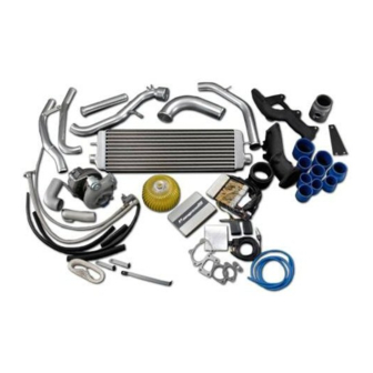
1. Parts List 1. Turbocharger T618Z 10cm P380 2. Exhaust Manifold Ductile Iron Cast 3. Downpipe Adapter Ductile Iron Cast 4. Intercooler Type 31C 5. Intercooler Bracket (Steel) 6. Suction Pipe (80 -60 Aluminum) “ (60 Aluminum with flange) 8. Compression Pipe (50 Aluminum flange elbow ) “... - Page 5 36. Silicone Hose 50 - 60 Reducer “ x 80 Reducer “ - 90 Reducer 39. Hose Band 16 “ “ “ “ 44. Gasket Compressor Inlet (Part # 14465-54C00) " Compressor Outlet (Part # 14465-05U11) " Turbine Inlet " Turbine Outlet "...
-
Page 6: Part List
Part List 24~26... - Page 7 30~32 33~35 36~38 39~43 50, 51 52, 53 54~56 62-66...
- Page 8 2. Factory Parts Removal When removing the stock parts, please refer to the factory RX8 Workshop manual for proper procedures. 2-1 Factory Parts Removal 1. Remove the engine cover and the battery cover. Disconnect the negative terminal of the battery. 2.
- Page 9 3. Turbo Kit Installation 3-1 Intake Manifold Plate Installation 1. Remove the extension manifold (upper). Please refer to RX8 workshop manual pages 01-13-4 to 01-13-11. Make sure to prevent any dirt or objects from entering the intake manifold. 2. Install the Intake Manifold Blocking Plate onto the manifold as shown in the picture.
- Page 10 3-3 Oil Pressure Line Installation 1. Remove the factory oil pressure switch at the left side of the rear rotor housing and install the Oil pressure line using the provided 3 way fitting, and straight fitting. Route the line to the right side of the engine (over the transmission) to connect to the turbo in the later step.
- Page 11 5. Connect the oil pressure line that was installed in the step 3-2 to the turbocharger. Install the turbocharger to the manifold using the provided gasket and hardware. (Parts Used #46, 66) 6. Reinstall the engine mount bracket and rubber, then remove the SST tool.
- Page 12 3-5 Intercooler Installation 1. Remove the auxiliary temp sensor on the bumper reinforcement, and rotate it 180 , then reinstall it back to the original mounting location. 2. Install the intercooler mounting bracket to the bumper reinforcement mounting bolt. Then install the intercooler to the bracket.
- Page 13 6. Secure C-5 bracket to the speed sensor harness bracket (LH). (Parts Used #11, 12, 13, 34, 35, 37, 41, 42, 56) 7. Reinstall the front stabilizer bar. 3-6 Airinx Installation 1. Install the suction pipe S-1 tot he S-2 using the provided hose and hose band.
- Page 14 4. Assemble the Airinx back together and hand tight the top screw. 5. Remove the factory Airflow meter off from the air cleaner box and install the Airflow mete to the provided air flow meter adapter. Install the Airinx and the adapter to suction Pipe S-1. * The O-ring on the Airflow meter will be reused.
- Page 15 2. Install the O2 sensor to the down pipe adapter and install the adapter to the Turbo using provided gasket and hardware. Connect the O2 sensor connector. (Parts Used #3, 47, 66) 3. Connect the Air Pump hose to the down pipe adapter.
- Page 16 3-8 e-manage Ultimate installation and vacuum hose connection for the actuator. 1. Remove the washer tank and drill a 1" hole on the fire wall. Make sure not to drill through any thing on the other side. There is a hump on the fire with a circle indentation behind the washer tank, which would be a perfect location to drill.
- Page 17 3-9 Bumper installation 1. Cut the under cover and the inner fender cover to clear the compression pipe. 2. Reinstall the front bumper.
- Page 18 GReddy Performance Products, Inc. is not responsible for any engine damage caused by over boosting (increased boost), modification to the kit, and/or misuse of the product.
Need help?
Do you have a question about the Turbo Kit Emanage Ultimate and is the answer not in the manual?
Questions and answers