Table of Contents
Advertisement
Quick Links
Advertisement
Table of Contents

Related Manuals for Q-See QS494


Summary of Contents for Q-See QS494
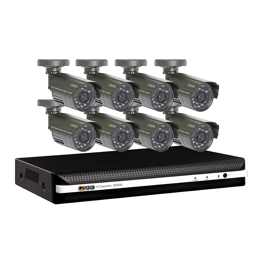
- Page 1 User Manual QS494 QS458 QS4716 QS558 QS4816 QS Series DVRs...
-
Page 2: About This Manual
About this Manual This manual is written for Q-See’s model QS494 and QS458 DVRs and was accurate at the time it was completed. However, because of our ongoing effort to constantly improve Thank You for Choosing a Q-See Product! our products, additional features and functions may have been added since that time and All of our products are backed by a conditional service warranty covering all hardware for 12 on-screen displays may change. -
Page 3: Table Of Contents
7.2 Calculating the Recording Capacity of a Hard Disk Drive Display Record APPENDIX User A.1 Troubleshooting 4.6 Recording 4.7 Playback A.2 Product Specifications 4.8 File Management Q-SEE PRODUCT WARRANTY Locking and Unlocking Files Backing Up Files Questions or Comments? Contact Us... -
Page 4: Introduction
INTRODUCTION CHAPTER 1 To prevent damage to your Q-See product or injury to yourself or to others, read and understand the following safety precautions in their entirety before installing or using this equipment. Keep these safety instructions where all those who use the product will read them. -
Page 5: Features And Specifications
FEATURES AND SPECIFICATIONS Audio Recording This product offers the following features: One channel of audio recording capability. Smartphone Compatible 24/7 Scheduled Recording Access live footage directly from your iPhone, iPad as well as Android smartphones and Choose which days of the week and hours of the day you want to set your DVR to record or tablets. -
Page 6: Installation And Connection
Your system has one or more inputs to allow you to record sound to accompany the video recording from a camera. This can be accomplished using either an audio-equipped camera USB PORTS or a microphone co-located with the camera such as Q-See’s QSPMIC (Picture 2-4). The There are two USB ports on the rear panel of your DVR. -
Page 7: Qs494
QS494 REAR PANEL FRONT PANEL RJ45 VIDEO IN A-OUT 4 Channels QS494 POWER DC +12V A-IN V-OUT Item # Name/ Symbol Description Shows status of hard drive, network, and whether the DVR is INDICATORS currently recording. Item # Connector Description IR SENSOR IR Receiver for remote control. -
Page 8: Qs458
QS458 REAR PANEL FRONT PANEL RJ45 VIDEO A-OUT 4 Channels QS458 POWER DC +12V A-IN V-OUT Item # Name/ Symbol Description Shows status of hard drive, network, and whether the DVR is INDICATORS currently recording. Item # Connector Description IR SENSOR IR Receiver for remote control. -
Page 9: Qs4716
QS4716 REAR PANEL FRONT PANEL 16 Channels QS4716 VIDEO POWER AUDIO AUDIO CVBS DC +12V RJ45 ALM IN Item # Name/ Symbol Description Item # Connector Description Shows status of hard drive, network, and whether the DVR is VIDEO IN 16 BNC video inputs for connecting analog video cameras INDICATORS currently recording. -
Page 10: Qs558
QS558 REAR PANEL FRONT PANEL AUDIO IN VIDEO IN 8 Channels QS558 POWER DC +12V AUDIO CVBS HDMI E-SATA RJ45 ALM IN Item # Name/ Symbol Description Item # Connector Description Shows status of hard drive, network, and whether the DVR is Power Switch Turn the DVR off after shutting it down from the Menu. -
Page 11: Qs4816
QS4816 FRONT PANEL REAR PANEL 16 Channels QS4816 VIDEO POWER AUDIO AUDIO CVBS DC +12V HDMI E-SATA RJ45 ALM IN Item # Name/ Symbol Description Item # Connector Description Shows status of hard drive, network, and whether the DVR is VIDEO IN 16 BNC video inputs for connecting analog video cameras INDICATORS... -
Page 12: Controls
VIRTUAL KEYBOARD CONTROLS CHAPTER 3 The virtual keyboard is contextual. For example, it will only show digits when the field is for numeral entries. In fields where letters and symbols can be entered, users can switch between This DVR can be controlled through the USB mouse or with the remote control. We have the two keyboards by using the Shift key. -
Page 13: Remote Control
3.2 REMOTE CONTROL The buttons on the Remote Control operate in the same manner as on a conventional DVR remote. Some buttons have multiple functions depending on which menu is being accessed. Name/Symbol Function STANDBY Press to turn standby mode ON/OFF. LOGIN/LOCK If “Security”... -
Page 14: Basic Operation
4.2 SYSTEM LOGIN BASIC OPERATION CHAPTER 4 By default, the DVR will display the live video from one or more cameras after starting up. In This chapter is intended to help you get your DVR up and running before you activate any order to access the features, including playback of recorded video, you will need to log into advanced features which are covered in later chapters. -
Page 15: Main Menu
4.4 MAIN MENU DATE/TIME There are two tabs in this submenu. To access the Main Menu, click on the Start button in the Control Bar. If the Control Bar is not present, right-clicking on the screen will make it appear. Date/Time This tab allows you to set the date and The Main Menu is the primary means of accessing the full set of functions of the DVR. -
Page 16: Recording
4.6 RECORDING Schedule Tab The fundamental purpose of your DVR is to view live cameras as well as to record events as As stated earlier in this section, your DVR is configured to record when motion is detected they happen. This section covers how to configure the settings to best suit your requirements. 24/7. -
Page 17: Playback
4.7 PLAYBACK Once your DVR records video, the next step is search for - and play back - specific events. There are two methods available to play back files. Clicking on the Playback arrow at the far right of the Control Bar will begin playback of the day’s recordings. However, if you are looking for files recorded on a different day, or want to find a specific recording, clicking on the Search icon in the Main menu will open the Video Search window. -
Page 18: File Management
4.8 FILE MANAGEMENT BACKING UP FILES When you record an important event, you will want to ensure that it does not get erased by File backup is handled much in the same way as selecting files for playback and is done accident. -
Page 19: Advanced Operation
Color ADVANCED OPERATION CHAPTER 5 You can adjust the appearance of your camera’s feed on your monitor using these The previous chapters covered information needed to help you set up and operate the controls. It will not effect the video that’s essential functions of your DVR. -
Page 20: Advance Menu
5.2 ADVANCE MENU Adding, Editing and Deleting Users The settings within this menu cover how your camera interacts with the world around it - what If you wish to allow someone else to use your system, it is recommended that you give them events are triggered when it detects motion, or how you can access it remotely. -
Page 21: Network
Most of the settings in this menu were made using the Startup Wizard during your initial setup. This chapter is covered in the Remote Monitoring Guide that came on the CD included with your DVR. It is also available for download at Q-See.com/Support PICTURE 5-12... -
Page 22: Disk Management
5.3 DISK MANAGEMENT 5.4 INFORMATION This menu allows you to manage and monitor the hard drive(s) mounted within your DVR. You As its name implies, the sole purpose of this menu is to provide information about the status can check drive capacity, set overwrite status and format a new or existing hard drive. of various aspects of the DVR. -
Page 23: Online Users
Also like a typical computer, we release occasional firmware updates to address issues or space is a concern, you can adjust your improve functionality. These updates are available for free through our Help Site at Q-See. settings in the Record menu (see Section com/Support where they can be downloaded onto your computer and transferred to an empty 4.6 Recording). -
Page 24: Settings
SETTINGS PAN-TILT-ZOOM CAMERAS CHAPTER 6 Unlike computers, the DVR does not store its operating system (firmware) on the hard drive, but instead it stores it on the mother board so your settings will be retained even if you switch 6.1 CONNECTING A PTZ CAMERA hard drives. -
Page 25: Configuring And Controlling A Ptz Camera
6.2 CONFIGURING AND CONTROLLING A PTZ CAMERA PTZ Definitions and Descriptions: All activities regarding controlling the PTZ camera manually, or setting up automatic cruises, Parameter Settings What it Means take place in the PTZ control panel located in the Control Bar. Address 1-255 The address of the PTZ camera... -
Page 26: Controlling The P.t.z. Camera
Creating a Cruise CONTROLLING THE P.T.Z. CAMERA Once the P.T.Z. Control Panel is open, you can direct the camera by selecting its channel and STEP 1. Click on the Cruise Settings button using the directional controls. Click and hold to move the camera in the desired direction. to open the Cruise Settings window. -
Page 27: Hard Disk Drive
STEP 4. Connect the power and data HARD DISK DRIVE CHAPTER 7 cables. Press firmly, but do not Your DVR uses an A/V Rated 7200RPM 3.5” SATA (Serial Advanced Technology Attachment) force them onto the pins or you may hard disk drive and will support drives up to 2TB (terabytes). These drives are the current damage them. -
Page 28: Calculating The Recording Capacity Of Ahard Disk Drive
7.2 CALCULATING THE RECORDING CAPACITY OF A APPENDIX HARD DISK DRIVE A.1 TROUBLESHOOTING While the physical data capacity of a hard drive is fixed, how much video you can record upon it depends on your recording configurations. Higher quality recordings will take up more space 1. -
Page 29: Product Specifications
A.2 PRODUCT SPECIFICATIONS ITEM DEVICE SPECIFICATION ITEM DEVICE SPECIFICATION PARAMETER PARAMETER QS494 QS458 QS4716 QS558 QS4816 QS494 QS458 QS4716 QS558 QS4816 SYSTEM LANGUAGE English, French, Portuguese, Spanish ALARM ALARM INPUT VIDEO VIDEO IN 4 ch. 8 ch. 16 ch. 8 ch. 16 ch. -
Page 30: Q-See Product Warranty
Q-SEE PRODUCT WARRANTY Q-See is proud to back all of our products with a conditional service warranty covering all hardware for 12 months from the date of purchase. Additionally, our products also come with QUESTIONS OR COMMENTS? CONTACT US a free exchange policy that covers all manufacturing defects for one month from the date of purchase. - Page 31 Digital Peripheral Solutions, Inc. 8015 E. Crystal Drive Anaheim, CA 92807...