Table of Contents
Advertisement
Mode!No.WESY59840
Seria_ No.
WritetheseriaU n umber i nthe
space aboveforfuturereference,
SedaU N umber D ecaU ( under s eat)
Asa manufacturer, wearecom-
mittedto providingcomptete
customersatisfaction. I f you
havequestions, o r if thereare
missingor damaged parts,we
will guarantee
complete
satis-
faction through
direct assis-
tance from our factory.
TO AVOID DELAYS, PLEASE
CALL DIRECT TO OUR TOLL-
FREE CUSTOMER NOT LINE.
The trained
technicians
on our
customer
hot tine wil! provide
immediate
assistance,
free of
charge.
CUSTOMER HOT LINE:
1°877°992°5999
Mon.=Fd., 6 a.m.=6 p.m. MST
Read all precautions
and instruc-
tions in this manuat before
using this equipment.
Save this
manual for future reference.
Advertisement
Table of Contents

Related Manuals for Weider CROSS BAR MAX


Summary of Contents for Weider CROSS BAR MAX
- Page 1 Mode!No.WESY59840 Seria_ No. WritetheseriaU n umber i nthe space aboveforfuturereference, SedaU N umber D ecaU ( under s eat) Asa manufacturer, wearecom- mittedto providingcomptete customersatisfaction. I f you havequestions, o r if thereare missingor damaged parts,we will guarantee complete satis- faction through direct assis- tance from our factory.
- Page 2 TABLE OF CONTENTS WARNING DECAL PLACEMENT ............. iMPORTANT PRECAUTIONS ..............BEFORE YOU BEGIN ..............ASSEMBLY ................ADJUSTMENTS ................CABLE DIAGRAM ................. EXERCISE GUiDELiNES ..............ORDERING REPLACEMENT PARTS ..........Back Cover LiMiTED WARRANTY .............. Back Cover Note: A PART iDENTiFiCATiON CHART and a PART LIST/EXPLODED DRAWING are attached in the center of this manual.
- Page 3 iMPORTANT PRECAUTIONS AWARNING: To reduce the dsk ofserious read t he injury, following important precautions before using the resistance system. Read all instructions in this manual before three positions closest to the upright base, using the resistance system. Use the resist- or while standing on the base plate.
- Page 4 BEFORE YOU BEGIN Thank you for sebcting the innovative CrossBar by after reading this manual, phase call our Customer Service Department tolPfree at 1°877°992-5999, WELDER ''_MAX resistance system, The resistance sys- tem offers a sebction of stations designed to develop Monday through Friday, 6 a,m, until 6 p,m, Mountain every major muscb group of the body, Whether your Time (excluding holidays), To help us assist you, please...
- Page 5 Tighten all parts as you assemble them, unless instructed to do otherwise. This manua! iSdesigned to ensure that the resist- As you assemble the resistance system, make sure all parts are oriented as shown in the draw- most PeOPb, However, it iS impo_ant to reanize ings.
- Page 6 Attach a Wheel ( 31)totheoutside ofthe Base(1) withanMIOx 78mmBolt(81),threeMIO Washers ( 75),andan MIONylon Locknut ( 76), Do not overtightenthe Locknut;the Wheel mustbeableto turn easity. Attach the other Wheel (not shown} in the same manner. Orient the Cross Tube (11) as shown, with the welded tubes at the bottom, Attach the Cross Tube to the Upright (3) with two MIO x 147mm Carriage Bolts (73), two MIO Washers (75), and...
- Page 7 Attach the Lat Tower (4) to the Upright (3) with four M10 x 25mm Button Screws (87), and four M10 Lock VVashers (103). Attach the Name Hate (89) to the Lat Tower (4) with two M4 x 16mm Screws (62). 103 87 Attach two Eyebolts (34) to the Top Frame (10) with two M8 Washers (59) and two M8 Nylon...
- Page 8 Attach two 8mm Metal Spacers (97), a 60mm Metal Spacer (39), and two Bearing Wheeb (46) to one end of the Seat Carriage (12) with an M8 x 104mm BoUt(60) and an M8 Nybn Locknut (65) as shown, Make sure the parts are oriented second set of wheels shown in the inset drawing;...
- Page 9 12, Attach a Hastic Foot (53) to the Backrest Frame (15) with an M4 x 16mm Screw (62), Attach the two Guard Hates (17) to the inside of the Backrest Frame (15) with four M4 x 16mm Screws (62), 13, Attach the Backrest (14) to the Backrest Frame (15) with four 1/4"...
- Page 10 16, Locate the Fubrum (18) on the Lat Tower (4) (see the inset drawing), Slide the Tray (35) onto the :dges rods on the Fubrum, Make sure the Tray is ori- ented as shown in the drawing. Set the resistance bars into the Tray (35) in the following order: the lO-pound Removable Resistance Bar (67), the 20-pound Removable Resistance Bar (36), an 80-pound Resistance Bar...
- Page 11 20, Wrap the Long CaMe (80) under a 90mm Pulley (28) as shown, Attach the Pulley, a CaMe Trap (29), an MIO Washer (75), and two Finger Guards (110) to the Upright (3) with an MIO x 127mm Button BoUt(56) and an MIO NyUon Locknut (76), Note: The Bolt will be packaged sepearatly for identification.
- Page 12 24, Locatethe LegLeverCable(32),whichhastwo endsthatarethesameUength anda thirdend thatis longer, RoutetheUongest endoftheLegLeverCaMe (32)through thehoUe i nthe FrontLeg(6),and attach it inside of thehoUe i nthe LegLever ( 7) withtheShortPin(109)anda cotterPin(108), 25, Attach a 90mmPulley (28)insideofthe hoUe i n theFrontLeg(6)withan MIOx 91mmBoUt (90), two26mmSpacers (52),twoMIOWashers ( 75), andanMIONyUon Locknut ( 76),Makesurethe Pulleyis abovethe LegLeverCable(32}.
- Page 13 ADJUSTMENTS This section explains how to adjust the resistance system, See the EXERCISE GUiDELiNES on page 17 for important information about how to get the most benefit from your exercise program, Also, refer to the accompa- nying exercise guide to see the correct form for each exercise, Make sure all parts are properly tightened each time you use the resistance system, Replace worn parts immedi- ately, The resistance system can be cbaned with a damp cloth and a mild, non-abrasive detergent, Do not use solvents, The resistance bars can be cbaned with a vinyl and rubber protectant, availabb at an automotive or...
- Page 14 ATTACHING T HEACCESBORmEB Witha highpulley attached totheresistance s ystem (seeATTACHING THEHUGH P ULLEYS A NDLEG LEVER onpage13),attach a ShortHandb(49)tothe Short C aMe (33)witha CabbCHp (51). TheShort H andbs(49),LongHandbs (notshown), or AnkbStrap(notshown) c anbeattached totheLong CaMe (80)witha CaMe CHp (51), A ttach theCudBar (8)to theLegLever ( 7)witha CaMe CHp, Attach the LegPress Strap(notshown) t obothendsoftheLong Cabb,or theoptionaU Uat bartotheShortCabbs(33),...
- Page 15 ADJUSTING THE BACKREST The Backrest (14) can be used in a bvel position or one of three inclined positions. To use the Backrest in a bvel position, secure the Seat Carriage (12) to the adjustment hob in the Bench Rail (5) next to the Front Leg (6) (see ADJUSTING THE SEAT on page 13).
- Page 16 USmNG THE REMOVABLE RESmSTANCE BARS The Removabb Resistance Bars (36, 67) can be used 67 36 to exercise apart from the resistance system, as shown in the video or on the exercise guide, To remove a Resistance Bar, pull it out of the Tray (35), To repUace the RemovaMe Resistance Bars (36, 67), slide them into the Tray (35) from the side shown, so that the arrows on the rings point toward the Tray,...
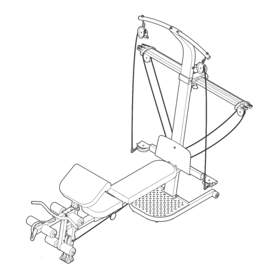
- Page 17 CABLE DIAGRAM The cable diagram shows the proper routing of the Long Cable (80), Use the diagram to make sure that Long CabJe (80} the cable has been assembled correctly, if the cable has not been correctly routed, the resistance system will not function properly and damage may occur, The numbers show the correct route for the cable,...
- Page 18 EXERCISE GUiDELiNES THE FOUR BASmC TYPES OF WORKOUTS PERSONALIZING YOUR EXERCISE PROGRAM Muscb Building Determining the exact length of time for each workout, as well as the number of repetitions or sets completed, To increase the size and strength of your muscles, is an individual matter, it is important to avoid overdo- push them close to their maximum capacity, Your mus- cues wHU continually adapt and grow as you progres-...
- Page 19 Rest for a short period of time after each set. The slowly as you stretch and do not bounce, Ease into ideaU resting periods are: each stretch gradually and go only as far as you can Rest for three minutes after each set for a muscle without strain, Stretching at the end of each workout building workout.
- Page 20 PART iDENTiFiCATiON CHART Refer to the drawings beUow to identify small parts used in assemMy, The number in parentheses beUow each drawing is the key number of the part, from the PART LUSTon the reverse side of this page, Note: Some small parts may have been pre-attached.
- Page 21 < 1/4" x 45mm BoUt (58) < MIO x 65ram Button Screw (70) MIO x 66ram Carriage BoUt (83) MIO x 72ram BoUt (64) < MIO x 78ram BoUt (81) MIO x 91ram BoUt (90) MIO x 103ram BoUt (66) <...
- Page 22 PART LiST--Model No. WESY59840 ROSO4A Key No. Qty. Description Key No. Qty. Description Base M8 Washer Base Hate M8 x 104mm Bolt Upright Long Pad Tube Lat Tower M4 x 16mm Screw Bench Rail 45mm Angled Inner Cap MIO x 72mm Bolt Front Leg Leg Lever M8 Nylon Locknut...
- Page 23 EXPLODED DRAWING--Model No. WESY59840 noso4A ..34 -_ 1 O0 _/65 40 ¸ 9_1 84 94 76 89 62 75 11076 '" 74 94 74 "110 463._ 104', 87 46 107- _ 63 75 / iii ii iii ii ' iii' 52 "_i iiiiii...
- Page 24 ORDERING REPLACEMENT PARTS To order repUacement parts, simpUy call our Customer Service Department toll-free at 1-877o992-5999, Monday through Friday, 6 a,m, until 6 p,m, Mountain Time (excluding holidays), To heUpus assist you, phase be pre- pared to give the following information: The MODEL NUMBER of the product (WESY59840) The NAME of the product (CrossBar by WEUDER MAX resistance system)
Need help?
Do you have a question about the CROSS BAR MAX and is the answer not in the manual?
Questions and answers