Advertisement
Model No. WESY59421
Serial No.
Write the serial number in the
space above for future reference.
Serial Number Decal (under seat)
QUESTIONS?
As a manufacturer,
we are com-
mitred to providing
complete
customer
satisfaction.
If you
have questions,
or if there are
missing or damaged
parts, we
will guarantee
complete
satis-
faction through direct assis-
tance from our factory.
TO AVOID DELAYS, PLEASE
CALL DIRECT TO OUR TOLL-
FREE CUSTOMER
HOT LINE.
The trained technicians
on our
customer
hot line will provide
immediate
assistance,
free of
charge.
CUSTOMER HOT LINE:
1-800-999-3756
Mon.-Fri., 6 a.m.-6 p.m. MST
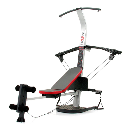
CR SS
USER'S MANUAL
www.TheCrossBow.com
Advertisement
Table of Contents

Related Manuals for Weider CROSS BOW


Summary of Contents for Weider CROSS BOW
- Page 1 Model No. WESY59421 CR SS Serial No. Write the serial number in the space above for future reference. Serial Number Decal (under seat) USER'S MANUAL QUESTIONS? As a manufacturer, we are com- mitred to providing complete customer satisfaction. If you have questions, or if there are missing or damaged...
-
Page 2: Table Of Contents
TABLE OF CONTENTS WARNING DECAL PLACEMENT ............IMPORTANT PRECAUTIONS ............. BEFORE YOU BEGIN ..............ASSEMBLY ................ADJUSTMENTS ..............CABLE DIAGRAM ..............EXERCISE GUIDELINES ............... ORDERING REPLACEMENT PARTS ..........Back Cover LIMITED WARRANTY ............Back Cover Note: A PART IDENTIFICATION CHART and a PART LIST/EXPLODED DRAWING are attached in the center of this manual. -
Page 3: Important Precautions
IMPORTANT PRECAUTIONS _WARN ING: To .du. risk of asdous injury, Bad the following Important precautions before using the resiStance system. Read ell inatructions In this manuel before t2. The resistance system is designed to be using the resistance system. Uas the resist- used with _ Included resistance, and the ance system only as described In this manuaL... -
Page 4: Before You Begin
BEFORE YOU BEGIN Thank you for selectingthe innovativeCrossBow by after readingthis manual, please call our Customer WELDER resistancesystem. The resistance system Service Department toil-free at 1-800-999-3756, offers a selectionof stationsdesignedto develop every Monday through Friday,6 a.m. until 6 p.m. Mountain major muscle groupof the body. -
Page 5: Assembly
ASSEMBLY • Tighten all parts as you assemble them. unless Make Thk'tg= F.al_r for Youmeif instructedto do otherwise. TNsm_ual _s €_ned.to_ thatmerest- • As you assemble the resistance system, make ante_ canhe'assembled s_ sure all parts are odented as shown in the draw- most people, However, it I_,i_= ntt0 reallz8 ings... - Page 6 Attach a Wheel (31) to the outside of the Base (1) with an M10 x 108mm Bolt (81), three M10 Washers (75), and an M1O Nylon Locknut(76). Do not overtighten the Nylon Locknut; the Wheel must be able to turn easily. Attach the other Wheel (not shown) in the same manner.
- Page 7 Attach the Lat Tower (4) to the Upright (3) with four M10 x 25mm Button Head Bolts (87), and four M19 Lock Washers (103). Attach the Name Plate (89) to the Lat Tower (4) with t_o M4 x 16mm Screws (62). °°...
- Page 8 Attach two 8mm Metal Spacers (97), a 60mm Metal Spacer (39), and two Bearing Wheels (46) to one end of the Seat Carriage (12) with an M8 x 104mm Bolt (60) and an M8 Nylon Locknut (65) _Attach second as shown. Be sure the parts are oriented as shown in the inset drawing;...
- Page 9 i2. Press two 25mm Square Inner Caps (54) into the indicated end of the Backrest Frame (15). Attach a Plastic Foot (53) to the Backrest Frame . 53 (15) with an M4 x 16ram Screw (62). L' 62 Attach the two Guard Plates (17) to the inside of L=-li :j oo the Backrest Frame (15) with four M4 x 16mm Screws (62).
- Page 10 16. Locate the Crossbow Fulcrum (18) on the Lat Tower (4) (see the inset drawing). Slide the Crossbow Spacer (35) onto the rods on the Crossbow Fulcrum. Make sure the Spacer is oriented as shown in the drawing. Set the Crossbows intothe CrossbowSpacer (35) in the followingorder: the 1O-PoundRemovable Crossbow(67), the 20-Pound Removable Rings on...
- Page 11 20. Wrap the Long Cable (80) under a 90mm Pulley (28) as shown. Attach the Pulley and a Pulley Guard (29) to the Upright (3) with an M10 x 113mm Button Head Bolt (40) and an M10 Nylon Locknut (76). Be sure the fiat edge of the Pulley Guard is on the bottom.
- Page 12 24.Locate the LegLeverCable(32), w hich hastwo endsthatarethesamelength anda thirdend thatislonger. Route thelongest endoftheLegLever C able (32)through t heholeintheFront L eg(6),and attach it inside oftheholeintheLegLever ( 7) withanM10x 6Omm Bolt(63) and an M10 Nylon Locknut (76). 25. Attach a 90mm Pulley (28) inside of the hole in the Front Leg (6) with an M10 x 91ram Bolt (90), two 26mm Spacers (52), two M10 Washers (75), end an MI0 Nylon Locknut (76).
-
Page 13: Adjustments
ADJUSTMENTS This section explains how to adjust the resistance system. See the EXERCISE GUIDELINES on page 17 for importantinformationabout how to get the most benefit from your exercise program. Also, refer to the accompa- nying exercise guide to see the correct form for each exercise. Make sure all parts are propedy tightened each time you use the resistancesystem. - Page 14 A'I-fACHING THE ACCESSORIES To attach a Short Handle (49) to a high pulley,flint attach the htgh pulley to the resistancesystem (see ATTACHING THE HIGH PULLEYS AND LEG LEVER on page 13). Then, attach the Short Handle to the Short Cable (33) with a Cable Clip (51). The Long Handles (not shown) and the Ankle Strap (not shown) can be attached to the Long Cable (80) wtthCable Clips (51).
- Page 15 ADJUSTING THE BACKREST The Backrest (14) can be used in a level positionor one of three inclined positions. To use the Backrest in a level position,secure the Seat Frame (12) to the adjustment hole in the Bench Rail (5) next to the Front Leg (6) (see ADJUSTING THE SEAT on page 13).
-
Page 16: Cable Diagram
USING THE REMOVABLE CROSSBOWS The Removable Crossbows (36, 67) can be used to 67 36 exercise apart from the resistancesystem, as shown in the video or on the exemise guide. To remove a Crossbow,pull it out of the CrossbowSpacer (35). To replace the Removable Crossbows (36, 67), slide them into the Crossbow Spacer (35) from the side shown, so that the arrows on the rings point toward... -
Page 17: Exercise Guidelines
EXERCISE GUIDELINES THE FOUR BASIC TYPES OF WORKOUTS PERSONALIZING YOUR EXERCISE PROGRAM Muscle Building Determiningthe exact length of time for each workout, To increase the size and strength of your muscles, as well as the number of repetitionsor sets completed, push them close to their maximum capacity.Your mus- is an individualmatter. - Page 18 Rest for a short period of time after each set. The slowly as you stretch and do not bounce. Ease into ideal resting periods are: each stretch gradually and go only as far as you can • Rest for three minutes after each set for a muscle without strain.
- Page 19 MONDAY EXERCISE RESISTANCE SETS REPS Date: AEROBIC EXERCISE TUESDAY Date: WEDNESDAY EXERCISE RESISTANCE SETS REPS Da_: THURSDAY AEROBIC EXERCISE Date: FRIDAY EXERCISE RESISTANCE SETS REPS Date: Make photocopiesof this page for schedulingand recordingyour workouts.
-
Page 20: Ordering Replacement Parts
ORDERING REPLACEMENT PARTS To order replacement pads, simply cell our Customer Service Department toll-free at 1-800-999-3756, Monday through Fdday, 6 a.m. until 6 p.m. Mountain Time (excluding holidays). To help us assistyou, please be pre- pared to give the followinginformation: •... - Page 21 PART IDENTIFICATION CHART Refer to the drawings below to identify small parts used in assembly.The number in parentheses below each drawing is the key number of the part, from the PART LIST on the reverse side of this page. Note: Some small parts may have been pre-attached.
- Page 22 _\\\\\\\1 M10 x 65mm Button Head Bolt (70) M10 x 53ram Carraige Bolt (61) _\\\\\\\1 M10 x 68ram Bolt (56) M10 x 6Omm Bolt (63) _\\\\\\\1 _\\\\\\ M10 X 66mm Carriage Bolt (83) M8 x 45ram Bolt (58) _\\\\\\\l M10 x 72ram Bolt (64) M10 x 42ram Button Head Bolt (71) _\\\\\\\1 M10 x 91mm Bolt (90)
- Page 23 PART LISTmModel No. WESY59421 R1202B Key No. Qty. Description Key No. Qty. Description Base M10 x 68mm Bolt Base Plate M8 x 114mm Bolt Upright M6 x 45mm Bolt Lat Tower M8 Washer Bench Rail M8 x 104mm Bolt Front Leg M10 x 53mm Carriage Bolt Leg Lever M4 x 16mm Screw...
- Page 24 EXPLODED DRAWINGmModel No. WESY59421 R1202B .-" _.-_8 .--'" ° ° 102"_...
Need help?
Do you have a question about the CROSS BOW and is the answer not in the manual?
Questions and answers