Table of Contents
Advertisement
®
Operator's
Manual
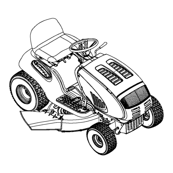
Pedal Drive Lawn Tractor
Models LTX-1842
LTX-2146
IMPORTANT:
Read safety rules and instructions
carefully
before operating
equipment.
Warning:
This unit is equipped with an internal combustion
engine and should not be used on or near any unimproved
forest-covered,
brush-covered
or grass-covered
land unless the engine's exhaust system is equipped with a spark arrester meeting applicable local or state
laws (if any). If a spark arrester is used, it should be maintained
in effective working order by the operator. In the State of California the
above is required by law (Section 4442 of the California Public Resources
Code). Other states may have similar laws. Federal laws apply
on federal lands. A spark arrester for the muffler is available through your nearest engine authorized service dealer or contac_ the service
department,
P.O. Box 361131 Cleveland, Ohio 44136-0019.
TROY-BILT LLC.P.O.BOX361131, CLEVELAND, OHiO 44136-0019
PRINTED IN U.S.A.
FORM
NO. 770-10490B
(2/2003)
Advertisement
Table of Contents

Related Manuals for Troy-Bilt LTX-2146


Summary of Contents for Troy-Bilt LTX-2146
- Page 1 A spark arrester for the muffler is available through your nearest engine authorized service dealer or contac_ the service department, P.O. Box 361131 Cleveland, Ohio 44136-0019. TROY-BILT LLC.P.O.BOX361131, CLEVELAND, OHiO 44136-0019 PRINTED IN U.S.A. FORM NO. 770-10490B...
- Page 2 TABLEOFCONTENTS Content Page Important Safe Operation Practices ..............Slope Gauge ...................... Tractor Set-up ....................Know Your Lawn Tractor ................... Operating Your Lawn Tractor ................Making Adjustments ..................Maintaining Your Lawn Tractor ................Service ......................Off-Season Storage ................... Attachments & Accessories ................Troubleshooting ....................
- Page 3 SECTION 1: IMPORTANT SAFEOPERATION P RACTICES WARNING: This symbol points out important safety instructions which, if not followed, could endanger the personal safety and/or property of yourself and others. Read and follow all instructions in this manual before attempting to operate this machine. Failure to comply with these instructions may result in personal injury.
- Page 4 23. Muffler a nd engine become hot and can cause a Keep all movement on the slopes slow and gradual. burn. Do not touch. Do not make sudden changes in speed or direction. 24. Check overhead clearances carefully before ddving Rapid engagement or braking could cause the front under low tree branches, wires, door openings etc., of the machine to lift and rapidly flip over backwards...
- Page 5 Never over fill fuel tank. Fill tank to no more feature emphasises not to cut in reverse and than ½ inch below bottom of filler neck to to avoid back-over accidents; do not defeat it. Keep children away from hot or running allow space for fuel expansion.
- Page 6 10.Never a ttempt to make adjustments or repairs to maximum safe operating speed of the engine. the machine while the engine is running. 13. Maintain or replace safety and instruction labels, as 11. Grass catcher components and the discharge necessary. cover are subject to wear and damage which could 14.
- Page 7 SIGHT AND HOLD THIS LEVEL WITH A VERTICAL TREE "11 A POWER POLE A CORNER OF A BUILDING OR A FENCE POST I,id WARNING Do not mow on inclines with a slope in excess of 15 degrees (a rise of approximately 2-1/2 feet every 10 feet). A riding mower could overturn and cause serious injury.
- Page 8 SECTION 3: TRACTOR SET-UP IMPORTANT:Your tractor is shipped with motor oil in the engine. However, you MUST check the oil level before starting the engine and operating. Refer to the separate Briggs & Stratton Operator/Owner Manual packed with your tractor. Read instructions carefully. NOTE: Any reference in this manual to the RIGHT or Locate the shipping brace and warning tag found LEFT side of the tractor is observed from operator's...
- Page 9 mulching, simply remove the mulch plug by GasandOilFill-up unthreading the plastic wing nut which fastens it to the The gasoline tank is located under the hood and has a cutting deck. This will allow the clippings to discharge capacity of either two or three gallons. Do not overfill. out of the discharge opening during operation.
- Page 10 SECTION 4: KNOW YOUR LAWNTRACTOR NOTE: S_eering Wheel not shown for clarity. Figure 4 Cruise Control Button PTO (Power Take-off) Lever Choke Control Ignition Switch Brake Pedal Parking Brake Button Shift Lever Drive Pedal Cup Holder Cargo Net (notshown) Deck Lift Lever Systems Indicator Monitod Hour Meter Throttle ControlLever...
- Page 11 ThrottleControl L ever DrivePedal The throttle control lever is located on the right side of The drive pedal is located below .,/_.,_ the tractor's dash panel. This lever controls the speed the brake pedal on the right front of the engine and, on model LTX-1842, when pushed side of the tractor along the all the way forward, the choke control also.
- Page 12 PTO(PowerTake-ofO Lever Systems IndicatorMonitor / HourMeter Your tractor is equipped with four indicator lights and an hour meter located on the left side of the dash panel. See Figure 2. Battery The PTO lever is located on the left side of the dashboard next to the steering wheel.
- Page 13 ShiftLever NOTE: Cruise control can NOT be engaged at the tractor's fastest ground speed. If the operator should The shift lever is located on the left side of the fender attempt tractor will automatically and has three positions, F (FORWARD), N (NEUTRAL) decelerate to the fastest optimal mowing ground speed.
- Page 14 IMPORTANT: DoNOTholdthekeyintheSTART Engaging the Parking Brake position forlonger t hantenseconds atatime.Doing so To engage the parking brake: maycause damage toyourengine's electric starter. Fully depress the brake pedal and hold it down with Aftertheengine starts, d eactivate t hechoke control your foot while gently pushing the parking brake andplace thethrottle control i ntheFAST position.
- Page 15 Disengage the cruise control using one of the following WARNING: Plan your mowing pattern to methods: avoid discharge of materials toward roads, Depress the brake pedal to disengage the cruise sidewalks, bystanders and the like. Also, avoid discharging material against a wall or control and stop the tractor.
- Page 16 42-inch Decks Carriag, To operate the cutting deck without mulching, simply remove the mulch plug by unthreading the plastic wing nut which fastens it to the cutting deck. This will allow the clippings to discharge out the side. See Figure 6. 46-inch Decks The mulch kit is packed separately within the tractor's crate.
- Page 17 Retighten the two jam nuts loosened earlier when LevelingtheDeck proper adjustment is achieved. NOTE: Check tractor's tire pressure before Side to Side performing any deck leveling adjustments. Refer to Tireson page 20 for information regarding tire pressure. If the cutting deck appears to be mowing unevenly, a side to side adjustment can be performed.
-
Page 18: Seat/Parking Brake Adjustment
SeatAdjustment To adjust the position of the seat, loosen the two knobs on the bottom of the seat. See Figure 9. Slide the seat Knobs forward or backward as desired. Retighten the two knobs. ParkingBrakeAdjustment WARNING: Never attempt to adjust the brakes while the engine is running. - Page 19 IMPORTANT: Refer t othe Briggs & Stratton Operator/ DeckWash System Owner Manual packed with your unit for information Your tractor's deck is equipped with a water port on its regarding the quantity and proper weight of motor oil. surface as part of its deck wash system. Use the Deck Wash System to rinse grass clippings Air Cleaner...
-
Page 20: Battery/Fuses
SECTION 8: SERVICE Battery Cutting Deck Removal The battery is sealed and is maintenance-free. Acid To remove the cutting deck, proceed as follows: levels cannot be checked. Place the PTO lever in the disengaged (OFF) position and engage the parking brake. Always keep the battery cables and terminals clean Lower the deck by moving the deck lift lever into the and free of corrosive build-up. -
Page 21: Changing Deck Belt & Pt0 Belt
To properly sharpen the cutting blades, remove equal amounts of metal from both ends of the blades along the cutting edges, parallel to the trailing edge, at a 25 ° to 30 ° angle. See Figure 12. IMPORTANT:If the cutting edge of the blade has already been sharpened to within 5/8"... -
Page 22: Changing Transmission Drive Belt
Route the new belts (deck belt first) as shown in Remount the belt guards removed earlier. Figure 14 or Figure 15. LTX-1842 Engine Pulley PTO Idler Bracket (mounted on tractor) _Deck Belt (Bottom) Left Hand Pulley PTO Belt (Top) Right Hand Pulley (beneath belt guard) Deck Idler Pulley Center Pulley... - Page 23 Battery Tray Shift Lever Drive belt (Lower) Variable*speed Opening Rear Idler Pulley Drive belt (Upper) Keeper Pins " _ e I1'1 till II01 _111 °lltl j_=j Engine Pulley Single*speed Transmission Pulley Transmission Front of Tractor NOTE: View shown from above tractor. Figure 16 Lower Drive Belt After disconnecting the battery cables, remove the...
- Page 24 Remove thehexboltfromthecenteroftheengine Remove both hairpin clips from the pin which is pulley andgently lower itoffoftheengine fastened to the speed control assembly (be careful crankshaft. Becareful nottoloseanywashers or not to lose the small flat washers found on the pin). spacers w hichmaybefound ontopoftheengine See Figure 18.
- Page 25 SECTION 9: OFF-SEASONSTORAGE Clean and lubricate the tractor as instructed in Section7: Follow the instructions in the Service, Storage & MAINTAINING YOUR LAWN TRACTOR o n page 18 of this Specifications section of the Briggs & Stratton manual before storing for an extended period. Operator/Owner Manual for proper engine care prior to storing your tractor.
- Page 26 SECTION 11: TROUBLESHOOTING Trouble Corrective Action Possible Cause(s) Engine fails to start PTO lever engaged. Place PTO lever in disengaged (OFF) position. Parking brake not engaged. Engage parking brake. Spark plug wire(s) disconnected. Connect wire(s) to spark plug. Throttle control lever not in correct Place throttle lever to FAST position.
-
Page 27: Parts List
SECTION 12: PARTS LIST FORMODELS LTX-1842& LTX-2146 NOTE: Engine accessory parts are applicable to all models except where otherwise noted. PART REF. PART DESCRIPTION DESCRIPTION 710-0227 Self-tapping Screw, #8-18 x.5 751-0650 RH Exhaust Pipe (Model LTX-2146) 710-0599 LH Exhaust Pipe (Model LTX-2146) Self4apping Screw, 1/4-20 x.5 751-0651 710-0604A... - Page 28 ModelsLTX-1842 & LTX-2146 > "-_>'-...
- Page 29 ModelsLTX-1842& LTX-2146 REF. PART DESCRIPTION 783-1346 Grill Support Bracket (9-style) 710-0599 Self-tapping Screw, 1/4-20 x .5 710-0528 Hex Cap Screw, 5/16-18 x 1.25 710-0924 Phillips Pan Screw, 1/4-20 x .75 710-1017 Truss Phillips Screw. 1/4-20 x .625 725-1741 Ignition Switch 735-04019 Side Panel Seal 710-0642...
- Page 30 ModelsLTX-1842 & LTX-2146 14/37...
- Page 31 ModelsLTX-1842 & LTX-2146 REF. PART DESCRIPTION 747-1130B Deck Stabilizer Rod 683-0197B Lift Shaft Assembly 711-0332 Clevis Pin, .5 x .78 712-0206 Hex Nut. 1/2-13 712-0431 Flange Lock Nut, 3/8-16 712-3004A Flange Lock Nut, 5/16-18 712-3083 Hex Nut. 1/2-13 714-0104 Internal Cotter Pin 714-0145 Internal Cotter Pin 716-0106...
- Page 32 ModelsLTX-1842 & LTX-2146 24-_ "1 " 25 37..®...
- Page 33 ModelsLTX-1842 & LTX-2146 REF. PART DESCRIPTION 710-1260A Self-tapping Screw, 5/16-18 x .75 710-0604A Self-tapping Screw, 16-18 x .625 783-0726B RH Pivot Support Bracket 783-0727A LH Pivot Support Bracket 783-0728 Pivot Bar Bracket 710-0514 Hex Cap Screw, 3/8-16 x 1 (Grade 5) 711-1408 RH Drag Link 711-1409A...
- Page 34 ModelsLTX-1842 & "13 IMPORTANT: For a proper working machine, use Factory Approved Parts. V-belts are designed to engage and disengage safely. A substitute (non OEM) V-belt can be dangerous by not disengaging completely. 21 " >...
- Page 35 ModelsLTX-1842 & LTX-2146 REF. PART REF. PART DESCRIPTION DESCRIPTION 783-1015 Shift Lever Support 754-0468 Upper Drive Belt 17840 Transaxle Mounting Bracket 756-0981A Flat Idler. 2.75 OD 618-0551A Single-speed Transmission Assembly 783-1016B Speed Control Rod Bracket 631-0009A Shifter Knob 783-0667B Transmission Torque Bracket 647-0045 Shift Lever 783-0669...
- Page 36 ModelsLTX-1842 & LTX-2146 "29 "3 \12:1: •...
- Page 37 ModelsLTX-1842 & LTX-2146 PART DESCRIPTION 716-0231 E-ring..75 721-0338 Seal, .75 x 1.0 x .125 711-1431 Drive Shaft 741-0340 Sleeve Bearing, .75 x .1.0 x 1.0 736-0495 Thrust Washer, 1.0 x .632 x .0 42-tooth Bevel Gear 717-1362 717-1363 42-tooth Bevel Gear 750-1234 Spacer, .633 x 1.0 x .513 718-0228...
- Page 38 ModelsLTX-1842 & --LTX-1842 t Refer to D on page 40. * Referto B on page 38,...
- Page 39 ModelsLTX-1842 & LTX-2146 REF. PART REF. PART DESCRIPTION DESCRIPTION 647-0064 Shoulder Screw, .625 x .5, 7/16-20 PTO Engage Lever Assembly 738-1020 683-0450 Bell Washer, .45 x 1.0 x .062 PTO Engage Plate Assembly 736-0407 710-0276 Carriage Screw, 5/16-18 x 1.00 712-0459 Flange Lock Nut, 7/16-20 710-0520...
- Page 40 ModelLTX-1842 * Refer to B on page 36.
- Page 41 ModelLTX-1842 REF. PART DESCRIPTION 711-04069 Grass Catcher Pin. 1/4-20 618-0574 Spindle Assembly, 5.75 Dia. w/Fitting 756-0980 Pulley Only 683-04051 42-inch Deck Shell 683-0254 Deck Adjustment Bracket w/Weld 736-0140 Flat Washer, .385 x .62 x .063 710-0520 Hex Cap Screw, 1/4-20 x 1.5 710-0528 Hex Cap Screw, 5/16-18 x 1.25 710-0726...
- Page 42 ModelLTX-2146 1_Refer to D on page 36.
- Page 43 ModelLTX-2141 REF. PART PART DESCRIPTION DESCRIPTION 711-04069 Retainer Hook 736-0119 Lock Washer. 5/16 17982 736-0270 Bell Washer, .265 x .75 x .062 Spindle Reinforcement Plate 618-0430A 738-0347 Spindle Assembly, 5.0 Dia. Shoulder Spacer, .625 x 1.16 Shoulder Screw 756-1187 738-0373 Pulley Only 618-0595 742-0611...
- Page 44 OIL SENSOR HEADL]GHTS HEADL]GHTS SEAT SWITCH 1439 "TO SWITCH 1716 REDtWHT SWITCH 1741 G+M+AI ALTERNATOR ALTERNATOR BRAKE SWITCH 1657A _OLENOID L+A2 1426 5TARTER G° I "L 6" STAR7 B+S+AI ITEM }ESCR[PT[01 SWITCH TRACTOR UNOCCUPIED BRAKE SWITCH...
- Page 45 777120884 777120883 777S30285 rModelLTX-1842: ,Model LTX-21461 777D06727 777120776 777D06940 777X40317 REFLECT VE INSERT BEHIND HEADLIGHT LENS 777D06942 777D06873...
- Page 46 NOTES...
- Page 47 NOTES...
- Page 48 MANUFACTURER'S LIMITED WARRANTY FOR: The limited warranty set forth below is given by Troy-Bilt LLC Troy-Bilt LLC does not extend any warranty for products sold or exported outside of the United States. with respect to new merchandise purchased and used in the United States, its possessions and territories.
Need help?
Do you have a question about the LTX-2146 and is the answer not in the manual?
Questions and answers