Table of Contents
Advertisement
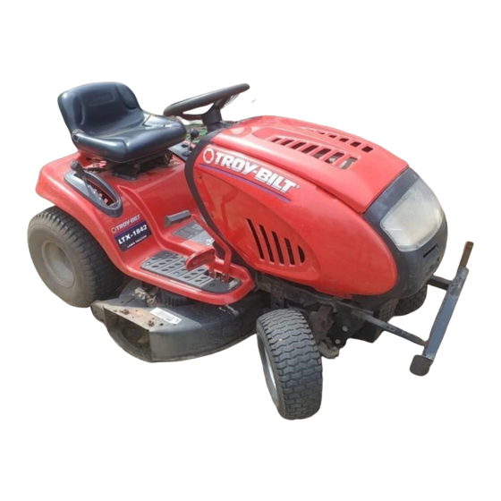
Operator's Manual
Pedal Drive Lawn Tractor
Models LTX-1842
LTX-2146
IMPORTANT: Read safety rules and instructions carefully before operating equipment.
Warning:
This unit is equipped with an internal combustion engine and should not be used on or near any unimproved forest-covered,
brush-covered or grass-covered land unless the engine's exhaust system is equipped with a spark arrester meeting applicable local or state
laws (if any). If a spark arrester is used, it should be maintained in effective working order by the operator. In the State of California the
above is required by law (Section 4442 of the California Public Resources Code). Other states may have similar laws. Federal laws apply
on federal lands. A spark arrester for the muffler is available through your nearest engine authorized service dealer or contact the service
department, P.O. Box 361131 Cleveland, Ohio 44136-0019.
TROY-BILT LLC. P.O. BOX 361131, CLEVELAND, OHIO 44136-0019
PRINTED IN U.S.A.
FORM NO. 770-10490B.fm
(2/2003)
Advertisement
Table of Contents

Related Manuals for Troy-Bilt LTX-1842


Summary of Contents for Troy-Bilt LTX-1842
- Page 1 A spark arrester for the muffler is available through your nearest engine authorized service dealer or contact the service department, P.O. Box 361131 Cleveland, Ohio 44136-0019. TROY-BILT LLC. P.O. BOX 361131, CLEVELAND, OHIO 44136-0019 PRINTED IN U.S.A.
-
Page 2: Table Of Contents
Off-Season Storage................... 25 Attachments & Accessories ................25 Troubleshooting....................26 Models LTX-1842 & LTX-2146 Parts List............27 FINDING MODEL NUMBER This Operator’s Manual is an important part of your new lawn tractor. It will help you assemble, prepare and maintain the unit for best performance. Please read and understand what it says. -
Page 3: Important Safe Operation Practices
SECTION 1: IMPORTANT SAFE OPERATION PRACTICES WARNING: This symbol points out important safety instructions which, if not followed, could endanger the personal safety and/or property of yourself and others. Read and follow all instructions in this manual before attempting to operate this machine. Failure to comply with these instructions may result in personal injury. -
Page 4: Slope Operation
23. Muffler and engine become hot and can cause a 5. Keep all movement on the slopes slow and gradual. burn. Do not touch. Do not make sudden changes in speed or direction. 24. Check overhead clearances carefully before driving Rapid engagement or braking could cause the front under low tree branches, wires, door openings etc., of the machine to lift and rapidly flip over backwards... - Page 5 feature emphasises not to cut in reverse and h. Never over fill fuel tank. Fill tank to no more to avoid back-over accidents; do not defeat it. than ½ inch below bottom of filler neck to g. Keep children away from hot or running allow space for fuel expansion.
- Page 6 10. Never attempt to make adjustments or repairs to maximum safe operating speed of the engine. the machine while the engine is running. 13. Maintain or replace safety and instruction labels, as 11. Grass catcher components and the discharge necessary. cover are subject to wear and damage which could 14.
-
Page 7: Slope Gauge
SECTION 2: SLOPE GAUGE... -
Page 8: Tractor Set-Up
SECTION 3: TRACTOR SET-UP Your tractor is shipped with motor oil in the engine. However, you MUST check the oil level before IMPORTANT: starting the engine and operating. Refer to the separate Briggs & Stratton Operator/Owner Manual packed with your tractor. Read instructions carefully. NOTE: Any reference in this manual to the RIGHT or •... - Page 9 However, you MUST check the oil level before operating. Be careful not to overfill. Identifying the Mulch Plug (if equipped) On tractor models LTX-1842, a mulch plug can be Mulch Plug (if equipped) Plastic Wing Nut (if equipped) found within the cutting deck’s discharge opening.
-
Page 10: Know Your Lawn Tractor
SECTION 4: KNOW YOUR LAWN TRACTOR NOTE: Steering Wheel not shown for clarity. Figure 4 PTO (Power Take-off) Lever Cruise Control Button Choke Control Ignition Switch Parking Brake Button Brake Pedal Shift Lever Drive Pedal Cup Holder Cargo Net (not shown) Systems Indicator Monitor/ Hour Meter M Deck Lift Lever G Throttle Control Lever... -
Page 11: Throttle Control Lever
This lever controls the speed the brake pedal on the right front of the engine and, on model LTX-1842, when pushed side of the tractor along the all the way forward, the choke control also. When set in running board. - Page 12 Systems Indicator Monitor / Hour Meter PTO (Power Take-off) Lever Your tractor is equipped with four indicator lights and an hour meter located on the left side of the dash panel. See Figure 2. Battery The PTO lever is located on the left side of the dashboard next to the steering wheel.
-
Page 13: Operating Your Lawn Tractor
Shift Lever NOTE: Cruise control can NOT be engaged at the tractor’s fastest ground speed. If the operator should The shift lever is located on the left side of the fender attempt to do so, the tractor will automatically and has three positions, F (FORWARD), N (NEUTRAL) decelerate to the fastest optimal mowing ground speed. -
Page 14: Engaging The Parking Brake
Engaging the Parking Brake Do NOT hold the key in the START IMPORTANT: position for longer than ten seconds at a time. Doing so To engage the parking brake: may cause damage to your engine’s electric starter. • Fully depress the brake pedal and hold it down with •... -
Page 15: Operating The Headlights
Disengage the cruise control using one of the following WARNING: Plan your mowing pattern to methods: avoid discharge of materials toward roads, sidewalks, bystanders and the like. Also, • Depress the brake pedal to disengage the cruise avoid discharging material against a wall or control and stop the tractor. -
Page 16: Making Adjustments
42-inch Decks To operate the cutting deck without mulching, simply Carriage Screw remove the mulch plug by unthreading the plastic wing nut which fastens it to the cutting deck. This will allow the clippings to discharge out the side. See Figure 6 . 46-inch Decks The mulch kit is packed separately within the tractor’s crate. -
Page 17: Leveling The Deck
Leveling the Deck • Retighten the two jam nuts loosened earlier when proper adjustment is achieved. NOTE: Check the tractor’s tire pressure before performing any deck leveling adjustments. Refer to Side to Side Tires on page 20 for information regarding tire pressure. If the cutting deck appears to be mowing unevenly, a side to side adjustment can be performed. -
Page 18: Maintaining Your Lawn Tractor
Seat Adjustment To adjust the position of the seat , loosen the two knobs on the bottom of the seat. See Figure 9. Slide the seat forward or backward as desired. Retighten the two Knobs knobs. Parking Brake Adjustment WARNING: Never attempt to adjust the brakes while the engine is running. - Page 19 Deck Wash System™ Refer to the Briggs & Stratton Operator/ IMPORTANT: Owner Manual packed with your unit for information Your tractor’s deck is equipped with a water port on its regarding the quantity and proper weight of motor oil. surface as part of its deck wash system. Use the Deck Wash System™...
-
Page 20: Battery
• After cleaning the battery and terminals, apply a • On model LTX-1842, remove the PTO belt from light coat of petroleum jelly or grease to both around the cutting deck’s center pulley. Refer to terminals. - Page 21 To properly sharpen the cutting blades, remove equal amounts of metal from both ends of the blades along the cutting edges, parallel to the trailing edge, at a 25° Support Pin to 30° angle. See Figure 12. If the cutting edge of the blade has already IMPORTANT: been sharpened to within 5/8"...
- Page 22 Route the new belts (deck belt first) as shown in • Remount the belt guards removed earlier. Figure 14 or Figure 15. Engine Pulley LTX-1842 PTO Idler Bracket (mounted on tractor) Deck Belt (Bottom) Left Hand Pulley PTO Belt (Top)
- Page 23 Battery Tray Variable-speed Drive belt (Lower) Shift Lever Opening Pulley Rear Idler Pulley Drive belt (Upper) Belt Keeper Front Idler Pulley Idler Bracket Keeper Pins to drive pedal Double-Idler Bracket Engine Pulley Transmission Idler Pulley Single-speed Transmission Pulley Transmission Front of Tractor NOTE: View shown from above tractor.
- Page 24 • Remove the hex bolt from the center of the engine • Remove both hairpin clips from the pin which is pulley and gently lower it off of the engine fastened to the speed control assembly (be careful crankshaft. Be careful not to lose any washers or not to lose the small flat washers found on the pin).
-
Page 25: Off-Season Storage
1-866-840-6483 for information regarding price and availability. NOTE: Lawn tractor models LTX-1842 & LTX-2146 are NOT designed for use with any type of ground-engaging attachments (e.g. tiller or plow). Use of this type of equipment WILL void the tractor’s warranty. -
Page 26: Troubleshooting
SECTION 11: TROUBLESHOOTING Trouble Possible Cause(s) Corrective Action Engine fails to start PTO lever engaged. Place PTO lever in disengaged (OFF) position. Parking brake not engaged. Engage parking brake. Spark plug wire(s) disconnected. Connect wire(s) to spark plug. Throttle control lever not in correct Place throttle lever to FAST position. -
Page 27: Models Ltx-1842 & Ltx-2146 Parts List
SECTION 12: PARTS LIST FOR MODELS LTX-1842 & LTX-2146 (for choke) NOTE: Engine accessory parts are applicable to all models except where otherwise noted. REF. PART REF. PART DESCRIPTION DESCRIPTION 710-0227 Self-tapping Screw, #8-18 x .5 751-0650 RH Exhaust Pipe (Model LTX-2146) 710-0599 Self-tapping Screw, 1/4-20 x .5... - Page 28 Models LTX-1842 & LTX-2146...
- Page 29 Models LTX-1842 & LTX-2146 REF. PART DESCRIPTION 783-1346 Grill Support Bracket (9-style) 710-0599 Self-tapping Screw, 1/4-20 x .5 710-0528 Hex Cap Screw, 5/16-18 x 1.25 710-0924 Phillips Pan Screw, 1/4-20 x .75 710-1017 Truss Phillips Screw, 1/4-20 x .625 725-1741...
- Page 30 Models LTX-1842 & LTX-2146 14/37...
- Page 31 Models LTX-1842 & LTX-2146 REF. PART DESCRIPTION 747-1130B Deck Stabilizer Rod 683-0197B Lift Shaft Assembly 711-0332 Clevis Pin, .5 x .78 712-0206 Hex Nut, 1/2-13 712-0431 Flange Lock Nut, 3/8-16 712-3004A Flange Lock Nut, 5/16-18 712-3083 Hex Nut, 1/2-13 714-0104...
- Page 32 Models LTX-1842 & LTX-2146...
- Page 33 Shoulder Spacer, .38 ID 631-04008 Steering Wheel, Soft Grip, Three Spoke 731-04066 Steering Wheel Cover 638-0019A LH Axle Assembly, .625 Dia.(Model LTX-1842) 638-0021 LH Axle Assembly .625 / .750 Dia.(Model LTX-2146) 638-0020A RH Axle Assembly, .625 Dia.(Model LTX-1842) 638-0022 RH Axle Assembly .625 / .750 Dia. (Model LTX-...
- Page 34 Models LTX-1842 & LTX-2146 For a proper IMPORTANT: working machine, use Factory Approved Parts. V-belts are designed to engage and disengage safely. A substitute (non OEM) V-belt can be dangerous by not disengaging completely.
- Page 35 Models LTX-1842 & LTX-2146 REF. PART REF. PART DESCRIPTION DESCRIPTION 783-1015 Shift Lever Support 754-0468 Upper Drive Belt 17840 Transaxle Mounting Bracket 756-0981A Flat Idler, 2.75 OD 618-0551A Single-speed Transmission Assembly 783-1016B Speed Control Rod Bracket 631-0009A Shifter Knob 783-0667B...
- Page 36 Models LTX-1842 & LTX-2146 12† 12‡ 12‡...
- Page 37 Models LTX-1842 & LTX-2146 REF. PART DESCRIPTION 716-0231 E-ring, .75 721-0338 Seal, .75 x 1.0 x .125 711-1431 Drive Shaft 741-0340 Sleeve Bearing, .75 x .1.0 x 1.0 736-0495 Thrust Washer, 1.0 x .632 x .0 717-1362 42-tooth Bevel Gear...
- Page 38 Models LTX-1842 & LTX-2146 LTX-1842 LTX-2146 † † Refer to D on page 40. * Refer to B on page 38.
-
Page 39: Parts
Engine Pulley, 3.56 OD x 5.56 736-0300 Flat Washer, .406 x .875 x .059 736-0331 Bell Washer, .39 x 1.13 x .062 754-0497 PTO Belt ( Model LTX-1842) 783-0653F Steering Support Bracket 736-3010 Flat Washer, .407 x .812 x .135 738-0372B Shoulder Spacer, .380... - Page 40 Model LTX-1842 * Refer to B on page 36.
- Page 41 Model LTX-1842 REF. PART DESCRIPTION 711-04069 Grass Catcher Pin, 1/4-20 618-0574 Spindle Assembly, 5.75 Dia. w/ Fitting 756-0980 Pulley Only 683-04051 42-inch Deck Shell 683-0254 Deck Adjustment Bracket w/ Weld Nut 736-0140 Flat Washer, .385 x .62 x .063 710-0520 Hex Cap Screw, 1/4-20 x 1.5...
- Page 42 Model LTX-2146 † † Refer to D on page 36.
- Page 43 Model LTX-2146 REF. PART REF. PART DESCRIPTION DESCRIPTION 736-0119 Lock Washer, 5/16 711-04069 Retainer Hook 17982 Spindle Reinforcement Plate 736-0270 Bell Washer, .265 x .75 x .062 618-0430A Spindle Assembly, 5.0 Dia. 738-0347 Shoulder Spacer, .625 x 1.16 738-0373 Shoulder Screw 756-1187 Pulley Only 618-0595...
- Page 44 Models LTX-1842 & LTX-2146...
- Page 45 Models LTX-1842 & LTX-2146...
- Page 46 NOTES...
- Page 47 NOTES...
- Page 48 MANUFACTURER’S LIMITED WARRANTY FOR: The limited warranty set forth below is given by Troy-Bilt LLC Troy-Bilt LLC does not extend any warranty for with respect to new merchandise purchased and used in the products sold or exported outside of the United States, United States, its possessions and territories.
Need help?
Do you have a question about the LTX-1842 and is the answer not in the manual?
Questions and answers