Table of Contents
Advertisement
Operator's
Manual
CRRFr MRN
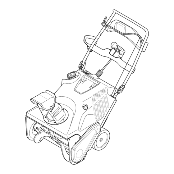
21" SNOW THROWER
Model No. 247.88782
CAUTION:
Before
using
this product,
read this
manual
and follow
all
safety
rules
and operating
instructions.
o SAFETY
ASSEMBLY
OPERATION
MAINTENANCE
PARTS LIST
o ESPANOL
Sears Brands
Management
Corporation,
Hoffman
Estates,
IL 60179, U.S.A.
Visit our website:
www.craftsman.com
FORM1/0. 769-07096A
7/27/2011
Advertisement
Table of Contents

Related Manuals for Craftsman 247.88782


Summary of Contents for Craftsman 247.88782
- Page 1 SAFETY ASSEMBLY OPERATION MAINTENANCE PARTS LIST CAUTION: Before using o ESPANOL this product, read this manual and follow safety rules and operating instructions. Sears Brands Management Corporation, Hoffman Estates, IL 60179, U.S.A. Visit our website: www.craftsman.com FORM1/0. 769-07096A 7/27/2011...
- Page 2 This warrantyis void if this productis everusedwhile providingcommercialservicesor if rentedto anotherperson. For warranty coverage details to obtain repairor replacement, v isit the web site: www.craftsman.com This warranty covers ONLYdefects in material and workmanship. Warranty coverage does NOT include: •...
-
Page 3: California Proposition
This machinewas builtto be operatedaccordingto the safeopera- This symbolpointsout importantsafetyinstructionswhich,if not tion practicesin this manual.As with anytype of powerequipment, followed,couldendangerthepersonalsafetyand/orpropertyof carelessnessor error on the partof the operatorcan resultin serious yourselfand others. Readand followall instructionsin this manual injury.This machineis capableof amputatingfingers,hands,toes beforeattemptingto operatethis machine.Failureto complywith and feet and throwingdebris.Failureto observethe followingsafety these instructionsmay resultin personalinjury.Whenyou seethis... -
Page 4: Operation
Safe Handling of Gasoline • Exerciseextremecautionwhenoperatingon or crossinggravel surfaces.Stay alertfor hidden hazardsor traffic. Toavoidpersonalinjuryor propertydamageuseextremecare in handlinggasoline.Gasolineis extremelyflammableand the vaporsare Exercisecautionwhenchangingdirectionand whileoperatingon explosive.Seriouspersonalinjurycan occurwhengasolineis spilled slopes. on yourselfor yourclotheswhichcan ignite. Washyour skin and Planyoursnow-throwing patternto avoiddischargetowards changeclothesimmediately. windows,walls,cars etc. Thus,avoidingpossibleproperty •... -
Page 5: Maintenance
MAINTENANCE & STORAGE DO NOT MODIFY ENGINE • Nevertamperwith safetydevices.Checktheirproperoperation Toavoidseriousinjuryor death,do not modifyengine in any way. regularly.Referto the maintenance and adjustmentsectionsof Tampering with the governorsettingcanlead to a runawayengineand this manual. cause it to operateat unsafespeeds.Nevertamperwithfactory setting of engine governor. •... - Page 6 SAFETY SYMBOLS This pagedepictsand describessafetysymbolsthat mayappear on this product. Read,understand,and followall instructionson the machine beforeattemptingto assembleand operate. READ THE OPERATOR'S MANUAL(S) Read, understand, and follow all instructions in the manual(s) before attempting to assemble operate WARNING-- ROTATING BLADES Keep hands out of inlet and discharge openings while machine is running.
- Page 7 NOTE:All referencesto the left or rightside of the snowthrowerare Pivotthe upperhandleinto theoperatingposition.Be surenotto fromthe operator'sposition.Anyexceptionswill be noted. pinch anyof the cablesin the process.See Figure2. UNPACKING THE SNOW THROWER Openthe top of the carton. Cut downthe cornerson the front of thecarton and folddown the front side.
- Page 8 installing the Chute Installing the Chute Rotation Control Assembly Removethe fourhex washerscrewsfrom the back of the handle Removethehex washerscrewsin the chute base.See Figure4. (twoon eachside). See Figure6. HexWasher Screw_, Figure4 Figure6 Align theholes in the chutebasewith the holesin the lowerchute and securewith the previouslyremovedhex washerscrews.See Usingthefour hexwasherscrews,install thechute rotation Figure5.
- Page 9 Removethe screwand hex lock nutfrom the universaljoint. See Installing the Recoil Starter Handle Figure8. Removethe eyebolt and handleknobfrom the manualbag. Placetheeyeboltand handle knobon the upperhandle as shownin Figure10.Donotfullytighten the hardware untilinstructed to do so. Universal Join{ Hex Lock Nut Screw Handle Knob Hex Lock Nut...
- Page 10 Alwayskeephandsand feet clearof equipmentmovingparts.Do not usea pressurizedstartingfluid. Vaporsare flammable. Removethegascap, checkthefuel leveland addfuel if necessary. Fillthetank untilthefuel reaches1/2"belowthebottomof thefiller neckto allowfor fuelexpansion. B e carefulnotto overfill. Checking and Adding Theengineis shippedwithoutoil in theengine.Youmustfill the enginewith oil beforeoperating.Runningthe enginewith insufficient oil can causeseriousenginedamageand void the productwarranty. Placethe snowthroweron a flat, levelsurface.
-
Page 11: Choke Control
Auger RecoilStarter Handle ElectricStarter Button ChuteRotation ElectricStarterOutlet Gas Cap ChuteAssembl' Shave Oil Drain Figure Nowthat you haveset up your snowthrower,it's importantto become acquainted with its controlsand features.Referto Figure12. The key is a safetydevice.It must be fully insertedin CHOKE CONTROL order for theengineto start. Removethe key whenthe snowthroweris not in use. - Page 12 CHUTE ROTATION CONTROL Insertignitionkey into slot.Makesure it snapsinto place.Do not attemptto turn the key.See Figure13. Thechute rotatecontrolis locatedin the centerof the controlpanel and controlsthe directionsnowis thrown.Depressthe buttonand rotatethe chute rotationcontrolto the rightto turnthe chuteto the right and rotateto the left to turn the chuteto the left. CHUTE ASSEMBLY The pitchof the dischargechute controlsthe angleat which the snow is thrown.Loosenthe wing knobon the side of the dischargechute...
-
Page 13: Stopping The Engine
STOPPING THE ENGINE Pushthechoke leverto the CHOKEI'e,I position. Runthe enginefor a few minuteswithoutload beforestoppingto If theengine is warm,placethe choke in the RUNi ! position helpdry off anymoistureon theengine. insteadof CHOKEI_1. To stopthe engine removethe keyand storeit in a safe place. Wipeall the snowand moistureawayfrom the enginecontrols Pushthe primerthree(3) times, makingsureto coverthe vent area. -
Page 14: Engine Maintenance
MAINTENANCE SCHEDULE Beforeperforminganytype of maintenance/service, disengageall Followthe maintenance schedulegiven below.This chart describes controlsand stopthe engine.Wait untilall movingparts havecome serviceguidelinesonly. Usethe ServiceLog columnto keeptrackof to a completestop.Disconnectsparkplug wireand groundit against completedmaintenance tasks.To locate the nearest Sears Service the engineto preventunintendedstarting.Alwayswearsafetyglasses Centeror to scheduleservice,simplycontactSearsat 1-800-4-MY-HOME®. - Page 15 Drainfuelfrom the tank by runningtheengine untilthe fueltank is Refillwith the recommended oil and checktheoil level; referto empty.Be surethe fuel fill capis secure. Checkingand AddingOil in the AssemblySection. Removethethreescrewsthat securethelowerpanel.Remove the Reinstall t he oil fillercap/dipsticksecurely. lowerpanelby liftingup on the panelto freethetabs atthe bottom Re-install t he lowerpanel byplacingthetabs in the tab slots, d thepanelfromthetab slotsandthenpull back.See Figure16.
- Page 16 Measurethe plug gap with a feelergauge.Correctas necessary Removingdebriswillinsureadequatecooling,correctengine speed and reducethe risk of fire. by bendingthe side electrode,Figure19.The gap shouldbe set to .02-.03inches (0.60-0.80ram). Donotspraytheenginewithwatertocleanit becausethewatercould contaminate the fuel.Usinga gardenhoseor pressure washingequip- mentcan alsoforcewaterintothe muffleropening.Waterthat passes throughthemufflercanentertheenginecylinder and causedamage. Electrode Accumulation of debrisaroundthe mufflercouldcausea fire.
-
Page 17: Auger Drive Belt Replacement
4. Tip the snow thrower back t othe operating position and pull t he AUGER DRIVE BELT REPLACEMENT starter handle afew times t osee ifitisdifficult topull. Runthe snowthroweruntilthe fueltank is empty. 5. Ifthe starter isdifficult topull, r emove the spark plug and pull t he Pullthe recoilstarterhandleuntil resistanceis felt.Thentip the handle several times t oensure that a ny oil t rapped inthe engine snowthrowerbackuntil it restson thehandles. - Page 18 To replacethe belt followthese instructionsand referto Figure24: Tochangethe rubberpaddles,proceedas followsand referto Figure Drive HexWasherScrew HexWasherScrew Figure24 Figure25 Routethe beltaroundthe drivepulleyand underthe idler pulley. Runthe snowthroweruntilthe fueltank is empty. Routethe end of the beltaroundthe auger pulleyand slidethe pulleybackon to the augershaft. It maybe necessaryto push Pullthe recoilstarterhandleuntil resistanceis felt.Then tip the snow throwerbackuntil it restson the handles.
-
Page 19: Preparing The Engine
If the snowthrowerwillnot be usedfor30 daysor longer,or if it is the end of the snowseasonwhenthe last possibilityof snowis gone,the equipmentneedsto be storedproperly.Followstorageinstructionsbelowto ensuretop performance from the snowthrowerfor manymoreyears. PREPARING THE ENGINE PREPARING SNOW THROWER Enginesstoredover30 days need to be drainedof fuel to prevent If the snowthrowerwill not be usedfor 30 days or longer,followthe instructionsbelow. - Page 20 Beforeperforming anytypeof maintenance/service, disengage all controlsandstopthe engine.Waituntilall moving partshavecometo a complete stop.Disconnect sparkplugwireandgrounditagainst t he engine to Iprevent u nintended starting. A lways wearsafetyglassesduringoperation orwhileperforming anyadjustments o r [repairs. This section addresses minor service issues. To locate the nearest Sears Service Center or to schedule service, simply contact Sears at 1-800-4-MY-HOME®.
- Page 21 This page intentionally left blank. Use this page to make any notes regarding your snow thrower.
- Page 22 Craftsman Snow Thrower Model 247.88782 _31)
- Page 23 Craftsman Snow Thrower IViodel 247.88782 684-04168 IdlerPulleyAssembly 750-04571 ShoulderSpacer 790-00426-0637 IdlerCable Bracket 984-04393 AugerAssembly 790-00444-4044 RHSide Plate 753-06469 Rubber Auger Paddle Kit (Includes 2 paddles and 12 hex washer screws) 790-00445-4044 LHSide Plate 684-04398-4044 FrameAssembly 790-00457-4044 BearingCup 710-0134 CarriageScrew,1/4-20x .62...
- Page 24 Craftsman Snow Thrower Model 247.88782 Ix • _...
- Page 25 Craftsman Snow Thrower IViodel 247.88782 631-04504 HandlePanel 631-04526P ChuteRotationControlAssembly 684-04350 Joint BlockAssembly 777X44559 LightLabel 710-04998 CarriageScrew,5/16-18x 1.00 _ 684-04383-0637_indicatorBracketAssembly 710-0451 CarriageBolt,5/16-18x .750 710-05348 EyeBolt, 1/4-20 710-05108 HexWasherScrew,1/4x .750 712-04064 FlangeLock Nut, 1/4-20 710-05179A MachineScrew,#8-32 x .88 720-0279 Wing Knob,1/4-20 710-0599 HexWasherScrew,1/4-20x 0.500...
- Page 26 Craftsman Engine IViodel 370=JU=11 For Snow IViodel 247.88782 102 _._. 100 710-04911 StudM8x36 951-12027 MufflerStudAssembly 951-11285 ExhaustPipe Gasket 712-04214 Nut,M8 951-12010 MufflerAssembly 710-05002 Bolt M5xl0 710-04915 Bolt M6x12 951-11104 CovernorSpringBracket 951-12016 GovernorShield 710-04920 Bolt M6x28 712-04212 Nut M6 951-12100 GovernorSpring...
- Page 27 Craftsman Engine IViodel 370=JU=11 For Snow IViodel 247.88782 710-04968 BoltM6x16 (Incl.6,8-17,19,22,27,28,41,45,46) 951-10292 951-11054 ValveCover SparkPlug/F6Rtc 726-04101 951-11572 Gasket,CylinderHead BreatherHose Clamp 731-07059 BreatherHose 951-10648 PushRodKit 951-11899 951-11565 ValveCoverGasket Tappet 715-04090 DowelPin 10x16 951-11892 RockerArm Assembly 751-11124 951-10647A ValveKit Nut,Pivot Locking 751-11123...
- Page 28 Craftsman Engine IViodel 370=JU=11 For Snow IViodel 247.88782 I Optional...
- Page 29 Craftsman Engine IViodel 370-JU-11 For Snow IViodel 247.88782 951-12111 951-11577 O-Ring15.8x2.5 PistonRingSet 951-11632 951-11368 Oil Seal,25x41.25x6 PistonPin Snap Ring 951-12007 Piston 951-11381 Oil Fill TubeO-Ring 951-11913 951-11633 PistonPin Oil Fill TubeAssembly 710-04915 BoltM6x12 951-11904 DipstickO-Ring 951-11113 Air Shield 951-12482 DipstickAssembly...
- Page 30 Craftsman Engine IViodel 370=JU=11 For Snow IViodel 247.88782...
- Page 31 Craftsman Engine IViodel 370=JU=11 For Snow IViodel 247.88782 LockWasher 710-05101 StudM6x110 951-11567 Carburetor InsulatorGasket IdleJet Assembly Gasket,ThrottlePlate 951-11568 Carburetor Insulator 951-11569A Carburetor Gasket IdleSpeedAdjustingScrew MixtureScrew 951-10639A PrimerAssembly 951-12019 PrimerHose 951-11824 PrimerBulb 951-11906 951-12098 HoseClamp Carburetor Assembly 951-11731 Carburetor Body FuelHoseClamp...
- Page 32 Craftsman Engine IViodel 370=JU=11 For Snow IViodel 247.88782 710-04915 BoltM6x12 951-12013 IgnitionCoil Assembly 710-04919 BoltM6x25 951-12050 Coil Assy/Stator 951-12051 Flywheel 951-10909 Fan,Cooling 951-10911 Pulley,Starter 712-04209 Nut,Special,M14x1.5 751-12644 BlowerHousing 736-04455 Gasket6 Washer 710-04974 BoltM6xlO 951-12015 RecoilStarter 731-05696 RecoilStarterHandle 951-10645A Startup Electromotor...
- Page 33 Craftsman Engine Model 370=JU=11 For Snow Model 247.88782 777123026 777123574 777122992...
- Page 34 Craftsman Snow Thrower IViodel 247.88782 777S34027 777122139 PULL STOP 777D16367 777X43688 DONor 777S33731 USE E85 OR FUEL CONTAINING MORE THAN10% ETHANOL 777S33118 777S32236 777122992 777D16557 777123463 777123574...
- Page 35 This page intentionally left blank. Use this page to make any notes regarding your snow thrower.
- Page 36 MTD CONSUMER GROUP (MTD), the California Air Resources Board (CARB) and the United States Environment Protection Agency (U. S. EPA) Emission Control System Warranty Statement (Owner's Defect Warranty Rights and Obligations) EMiSSiONCONTROLSYSTEM COVERAGE IS APPLICABLE TOCERTiFiEDENGINESPURCHASED IN CALIFORNIA IN 2005 ANDTHERE- AFTER,WHICHARE USEDIN CALiFORNiA,ANDTO CERTiFiEDMODELYEAR2005 AND LATERENGINESWHICHARE PURCHASED AND USEDELSEWHERE IN THE UNITEDSTATES.
- Page 37 (4)Repair orreplacement ofany warranted part under the warranty provisions ofthis article m ust beperformed atnocharge tothe owner ata warranty station. (5)Notwithstanding the provisions ofSubsection (4) above, warranty services orrepairs must beprovided atallMTD distribution centers that are franchised toservice the subject engines. (6)The owner must not b echarged fordiagnostic labor that l eads tothe determination that a warranted...
- Page 38 Look For Relevant Emissions Durability Period and Air index information On Your Engine Emissions Label Engines that are certified to meet the California Air Resources Board (CARB) Tier 2 Emission Standards must display information regarding the Emissions Durability Period and the Air Index. Sears Brands Management Corporation makes this information available to the consumer on our emission...
- Page 39 Congratulations on making a smart purchase. Your new Craftsman® product is designed manufactured for years of dependable operation. But like all products, it may require repair from time to time. That's when having a Repair Protection Agreement can save you money and aggravation.
- Page 40 La presentegarantiase anula si se utilizaeste productoalguna vezpara prestarservicioscornerciales o si se Ioalquilaa otra persona. Paraobtener informaci6n sobre el alcance de la garantiay solieitar la reparaci6no el reemplazo, v isite el sitio Web: www.craftsman.com Esta garanfia eubre0NiCAMENTElos defectos en los rnateriales y en la rnano de obra. Esta garanfia NOcubre: •...
- Page 41 Estam_quinaest_ dise_adapara set utilizadarespetandolasnormas La presenciade este sfmboloindica que setrata de instruccionesde de seguridadcontenidasen este manual.AI igual quecon cualquiertipo seguridad importantesquedebe respetarpara evitarponeren riesgosu de equipomotorizado,un descuidoo error por partedel operadorpuede seguridad personaly/o materialy la de losdemos.Leay cumplatodas las producir lesionesgraves.Esta m_quinaes capaz de amputardedos, instruccionesde este manualantesde intentaroperar esta m_quina.Si no manos y piesy de arrojar residuos.Deno respetarlas instruccionesde respetaestas instruccionespuedeprovocarlesionespersonales.Cuando...
- Page 42 • Planifiqueel patr6nen elque va air arrojandonieve para evitarque Manejo seguro de la gasolina la descargade materialse produzcahacia lasventanas,las paredes, Para evitarlesionespersonaleso da_os materialessea sumamentecuida- los autom6viles,etc. y evitarasi posiblesdaSosmaterialeso lesiones dosoal manipularla gasolina.La gasolina essumamenteinflamabley sus producidas porlos rebotes. vaporespuedencausar explosiones.Si se derramagasolinaencima o sobre la ropa se puedelesionargravementeya quese puedeencender.
-
Page 43: Mantenimiento Y Almacenamiento
MANTENIMIENTO Y ALMACENAMIENTO NO MODIFIQLIE EL MOTOR Nunca altere losdispositivosde seguridad.Controleperi6dicamente que Paraevitarlesionesgraveso la muerte, no modifiqueel motorde ninguna funcionencorrectamente.Remitasealas seccionesde mantenimientoy manera.Si altera laconfiguraci6ndel regulador,el motorse puededesbocar ajustede este manual. y funcionara velocidadesque no son seguras.Nunca cambiela configuraci6n de f_brica del reguladordel motor. •... - Page 44 SiMBOLOS DE SEGURIDAD En esta p_gina se presentan y describen los simbolos de seguridad que pueden aparecer en este producto. Lea, entienda y cumpla todas las instrucciones incluidas en la m_quina antes de intentar realizar el montaje de la unidad y utilizarla. _'"-_ LEA LOS MANUALES DEL OPERADOR Lea, entienda y cumpla todas las instrucciones...
-
Page 45: Montaje
NOTA:Todaslas referencias a losladosderechoo izquierdode la Gire la manijasuperiora la posici6nde funcionamiento. AsegOrese m_.quina quitanievese hacenobservandola rnismadesdela posici6n de no apretarlos cablesen el proceso.Veala Figura2. del operador.En casode que hubieseuna excepci6n,se especificar_. claramente. COMO DESEMBALAR LA MAQUINA QUITA- NIEVE Abra la partede arribade la caja. Corte lasesquinasdel frentede la caja y done haciaabajo el frente. - Page 46 Instalaci6n del canal Instalaci6n del montaje del control de rotaci6n del canal Extraigalostornillosde cabezahexagonal d e la basedel canal. Veala Figura4. Extraigalos cuatrotornillosde cabeza hexagonal d e la parte posteriorde la manija(dosa cadalado). Veala Figura6. Tornillo de cabeza hexagonal Figura4 Figura6 Alineelos orificiosde la basedel canalcon los orificiosdel canal Usandolos cuatrotornillosde cabezahexagonal,instaleel...
- Page 47 11. Retireel tornilloy la tuerca hexagonal d e la juntauniversal.Vea Instalaci6n de la manija del arrancador la Figura8. de retroceso Retireel perno de ojo y la periNa de la rnanijade la bolsadel manual. Coloqueel pernode ojo y la periNa de la rnanijaen la rnanija superiorcornose indicaen la Figura10.No ajustecornpleta- rnentelosherrajeshastaque se le indiqueque Io haga.
- Page 48 • Eviteel contactorepetidoo prolongado con la piel y la inhalaci6n Saqueel tap6n/la varillade rnedici6nde aceite.Si el niveles de los vapores. bajo,agreguelentarnente aceitehasta que el nivelregistradoest_ en un puntointerrnedioentrealto (H) y bajo (L), Figura11. Carga de combustible NOTA:No IoIleneen exceso.Si secargadernasiadoaceite se puede generarhurno,problernasde arranqueo suciedaden la bujfa.
- Page 49 Controlde la barrena Manijade Superior Faro Llave Manijadel arrancador Cebador de retroceso Bot6ndel arrancador Controlde rotaci6ndel canal Salidade[ arrancador_ el_ctrico L_,,,,J _ Tapade Palancadel cebador j Varillade Montajede[canal Ilenado/nive[ Silenciador Palancade[ Manijadel arrancad( [e retroceso Piacade raspado Drena del aceite Figura12 TAPON DE COMBUSTIBLE...
- Page 50 SILENCIADOR Insertela Nave de encendidoen la ranura.AsegOrese de que entre a presi6nen su lugar.No intentegirarla Nave. V eala Figura13. El escapedel motorsaledel motora travesdel silenciador. CONTROL DE ROTACION DEL CANAL El controlde rotaci6ndel canalest_ ubicadoen el centrodel panel de controly controlala direcci6nen que searroja la nieve.Oprirnael bot6ny roteel controlde rotaci6ndel canalhaciala derechapara girar el canal haciala derechay r6telohaciala izquierdaparaque el canal gire a la izquierda.
- Page 51 DETENCION DEL MOTOR Empujela palanca del cebadora la posici6n CHOKE(cebador)I'.,I Hagafuncionarel motorduranteunosminutossin cargaantesde Si el motorya est,. caliente,ubiqueel cebadoren la posici6n pararparaayudara secar la humedaden el motor. RUN(funcionamiento) _ _ _en lugarde CHOKE(cebador)i'_1. Paradetenerel motorsaquela Ilavey gu_.rdela en un lugar Presionetres (3) vecesel bot6nde cebado,asegur_.ndose d e seguro.
-
Page 52: Mantenimiento
PROGRAMA DE MANTENIMIENTO Antesde realizar c ualquier t ipode rnantenirniento o servicio, d e- Sigael cronograrnade rnantenirniento que se presentaa continuaci6n. senganche todosloscontroles y detengael motor.Espere a quese Estatabla s61o describepautasde servicio.Utilicela colurnnaRegistro detengan cornpletarnente todaslaspiezasrn6viles. D esconecte el cable de Serviciopara hacerel seguirniento de las tareasde rnantenirniento de la bujiay p6ngalo haciendo rnasacontrael motorparaevitarque se cornpletadas.Paraubicar el Centro de Servicio Searsm_s cercano... - Page 53 Vade el combustibledel dep6sitohaciendofuncionarel motor inclinela m_.quina quitanievehaciaatr_.sparadrenarel aceiteen hastaque el dep6sitode combustibleest6 vado. Cerci6resede el recipiente.El aceiteusadose debe descartaren un centrode recolecci6nadecuado. que el tap6nde Ilenadodel combustibleest,. bien ajustado. Extraigalostres tornilDsque sujetanel panel inferior.Extraigael Vuelvaa colocarel tap6nde drenajey ajOstelo bien. panelinferiorlevant_.ndolo p ara liberarlas leng(Jetas que est_.n en Vuelvaa Ilenarconel aceite recomendado y controleel nivelde la basedel panelde las ranuraspara lengOetas y luegotire hacia...
- Page 54 Midala separaci6nde bujia con un calibrador.Realicelosajustes La extracci6nde los residuosaseguraque el enfriarniento seaadec- necesariostorciendoel electrodolateral,Figura19.La separaci6n uado,la velocidaddel motorcorrectay el riesgode incendiornenor. debeajustarseen 0,02-0,03pulgadas(0,60-0,80rnrn). No rode el motorconagua para lirnpiarloporqueel agua podria contarninarel combustible.Si se utilizauna rnanguera de jardin o equipode lavadoa presi6ntarnbi_npuedeentraragua dentrode la aberturadel silenciador.El agua que pasapor el silenciadorpuede Electrodo...
- Page 55 Cable de control Aflojeloscuatrotuercasy lostornillosde bloqueode transporte que sujetanla placade afeitara la vivienda.Consultela Figura20. Esposibleque necesiterealizarajustesperi6dicos debidoal estirarnien- Muevael afeitadoplacaen la posicbn adecuaday vuelvaa apretar to del cablede controly de la correade transrnisi6n ocasionado por el lastuercasy lostornillos. desgaste.Si la barrenaparecetitubearrnientras gira,hagaIosiguiente: Elagujero superior d ela barradecontrol p reveel ajuste de latensi6n del cable.Pararealizar e l ajuste, d esconecte e l extrerno delcable de control d elagujero inferior d e larnanija decontrol e ins_rtelo enel agujero...
- Page 56 REENIPLAZO DE LA CORREA Extraigala polea de la barrenay la correa. DE TRANSMISION DE LA BARRENA Paravolvera colocarla correasiga estasinstrucciones y consulte la Figura24: Pongaen marchala m&quinaquitanievehastaque el tanquede combustible est_ vacio. Poleade transmisi6n Jale de la manijadel arrancadorde retrocesohasta sentir resistencia.Luegoincline la m_.quina quitanievehaciaatr_.s Polea Ioca hasta que quede apoyadasobre las manijas.
- Page 57 REENIPLAZO DE LAS PALETAS REEMPLAZO O REVERSO DE LA PLACA DE DE LA BARRENA RASPADO Las paletasde cauchode la barrenade la rn&quina quitanievese La placa de raspadoest,. adosadaal fondode la caja de la barrena y sujeta a desgaste.Se la debe controlar peri6dicarnente. L a placa desgastany se lasdebe carnbiarsi se presentansignosde desgaste excesivo.
- Page 58 Si no se va a utilizarla rn_.quina quitanievedurante30 diaso rn_.s, o si es el finalde la ternporadade nievey ya no existeposibilidadde que nieve,es necesarioalrnacenarel equipo de rnaneraadecuada.Siga lasinstruccionesde alrnacenarniento que seindicana continuaci6npara garantizarel rendirniento rn_.xirno de la rn_.quina quitanieveduranternuchosaSosrn_.s. PREPARACION DEL MOTOR PREPARACION DE LA M.&.QUINA QUITANIEVE...
- Page 59 Antes de realizarcualquier tipo de mantenimientoo servicio, desenganche todos los controles y detenga el motor. Esperea que se detenganI completamente todas las piezas m6vles. Desconecteel cable de la bujfa y p6ngalo haciendo masa contra el motor para evitar que se Ienc enda acc denta mente.
- Page 60 MTD CONSUMER GROUP, iNC. (MTD), el Bordo de Recursos de Aire de California (CARB) y la Agencia de Protecci6n Medioambiental de Estados Unidos (U. S. EPA) Declaraci6n de Garantia del Sistema de Control de Emisiones (Derechos y obligaciones del propietario seg_n la garantia contra defectos) LA COBERTURADESISTEMADECONTROLDEEMISIONES APLICABLE A MOTORES CERTIFICADOS COMPRADOS ENCALIFORNIA EN2005 Y A PARTIRDE ENTONCES, QUESON USADOS EN CALIFORNIA, Y HASTA ANO2005 DE MODELOCERTIFICADO Y MOTORES POSTERIORES QUESON COMPRADOS Y USADOSENOTRAPARTEEN LOSESTADOS UNIDOS.
- Page 61 reernplazada segQn lagarantia segarantizar_, por e lresto d el p eriodo degarantia. (3) Cualquier pieza g arantizada que est_ prograrnada para reernplazo segQn elrnantenirniento requerido deconforrnidad con lasinstruc- clones escritas delaSubsecci6n (c)segarantiza por e lperiodo detiernpo anterior alaprirnera fecha d ereernplazo prograrnada para e sa pieza.
- Page 62 Busque el periodo de duraci6n de emisiones importantes yla informaci6n de clasificaci6n de aire en la etiqueta de emisiones de su motor Los motores cuyo cumpiimiento con los estAndares de emisi6n Tier 2 de la Comisi6n de Recursos Ambientales de California (CARB) est6 certificado deben exhibir la informaci6n relacionada con el periodo de duraci6n de ias emisiones y la clasificaci6n de aire.
- Page 63 Felicitaciones por haber realizado una adquisici6n inteligente. El producto Craftsman® que ha adquirido esta diseSado y fabricado para brindar muchos aSos de funcionamiento confiable. Pero como todos los productos a veces puede requerir de reparaciones. Es en ese momento cuando...
- Page 64 Your Home For troubleshooting, product manuals and expert advice: managernylife www.managemylife.com For repair - in your home - of all major brand appliances, lawn and garden equipment, or heating and cooling systems, no matter who made it, no matter who sold it! For the replacement parts, accessories owner's manuals that you need to do-it-yourself.
- Page 65 SAFETY ASSEMBLY OPERATION MAINTENANCE PARTS LIST CAUTION: Before using o ESPANOL this product, read this manual and follow safety rules and operating instructions. Sears Brands Management Corporation, Hoffman Estates, IL 60179, U.S.A. Visit our website: www.craftsman.com FORM1/0. 769-07096A 7/27/2011...
- Page 66 This warrantyis void if this productis everusedwhile providingcommercialservicesor if rentedto anotherperson. For warranty coverage details to obtain repairor replacement, v isit the web site: www.craftsman.com This warranty covers ONLYdefects in material and workmanship. Warranty coverage does NOT include: •...
- Page 67 This machinewas builtto be operatedaccordingto the safeopera- This symbolpointsout importantsafetyinstructionswhich,if not tion practicesin this manual.As with anytype of powerequipment, followed,couldendangerthepersonalsafetyand/orpropertyof carelessnessor error on the partof the operatorcan resultin serious yourselfand others. Readand followall instructionsin this manual injury.This machineis capableof amputatingfingers,hands,toes beforeattemptingto operatethis machine.Failureto complywith and feet and throwingdebris.Failureto observethe followingsafety these instructionsmay resultin personalinjury.Whenyou seethis...
- Page 68 Safe Handling of Gasoline • Exerciseextremecautionwhenoperatingon or crossinggravel surfaces.Stay alertfor hidden hazardsor traffic. Toavoidpersonalinjuryor propertydamageuseextremecare in handlinggasoline.Gasolineis extremelyflammableand the vaporsare Exercisecautionwhenchangingdirectionand whileoperatingon explosive.Seriouspersonalinjurycan occurwhengasolineis spilled slopes. on yourselfor yourclotheswhichcan ignite. Washyour skin and Planyoursnow-throwing patternto avoiddischargetowards changeclothesimmediately. windows,walls,cars etc. Thus,avoidingpossibleproperty •...
-
Page 69: Maintenance
MAINTENANCE & STORAGE DO NOT MODIFY ENGINE • Nevertamperwith safetydevices.Checktheirproperoperation Toavoidseriousinjuryor death,do not modifyengine in any way. regularly.Referto the maintenance and adjustmentsectionsof Tampering with the governorsettingcanlead to a runawayengineand this manual. cause it to operateat unsafespeeds.Nevertamperwithfactory setting of engine governor. •... - Page 70 SAFETY SYMBOLS This pagedepictsand describessafetysymbolsthat mayappear on this product. Read,understand,and followall instructionson the machine beforeattemptingto assembleand operate. READ THE OPERATOR'S MANUAL(S) Read, understand, and follow all instructions in the manual(s) before attempting to assemble operate WARNING-- ROTATING BLADES Keep hands out of inlet and discharge openings while machine is running.
- Page 71 NOTE:All referencesto the left or rightside of the snowthrowerare Pivotthe upperhandleinto theoperatingposition.Be surenotto fromthe operator'sposition.Anyexceptionswill be noted. pinch anyof the cablesin the process.See Figure2. UNPACKING THE SNOW THROWER Openthe top of the carton. Cut downthe cornerson the front of thecarton and folddown the front side.
- Page 72 installing the Chute Installing the Chute Rotation Control Assembly Removethe fourhex washerscrewsfrom the back of the handle Removethehex washerscrewsin the chute base.See Figure4. (twoon eachside). See Figure6. HexWasher Screw_, Figure4 Figure6 Align theholes in the chutebasewith the holesin the lowerchute and securewith the previouslyremovedhex washerscrews.See Usingthefour hexwasherscrews,install thechute rotation Figure5.
- Page 73 Removethe screwand hex lock nutfrom the universaljoint. See Installing the Recoil Starter Handle Figure8. Removethe eyebolt and handleknobfrom the manualbag. Placetheeyeboltand handle knobon the upperhandle as shownin Figure10.Donotfullytighten the hardware untilinstructed to do so. Universal Join{ Hex Lock Nut Screw Handle Knob Hex Lock Nut...
- Page 74 Alwayskeephandsand feet clearof equipmentmovingparts.Do not usea pressurizedstartingfluid. Vaporsare flammable. Removethegascap, checkthefuel leveland addfuel if necessary. Fillthetank untilthefuel reaches1/2"belowthebottomof thefiller neckto allowfor fuelexpansion. B e carefulnotto overfill. Checking and Adding Theengineis shippedwithoutoil in theengine.Youmustfill the enginewith oil beforeoperating.Runningthe enginewith insufficient oil can causeseriousenginedamageand void the productwarranty. Placethe snowthroweron a flat, levelsurface.
- Page 75 Auger RecoilStarter Handle ElectricStarter Button ChuteRotation ElectricStarterOutlet Gas Cap ChuteAssembl' Shave Oil Drain Figure Nowthat you haveset up your snowthrower,it's importantto become acquainted with its controlsand features.Referto Figure12. The key is a safetydevice.It must be fully insertedin CHOKE CONTROL order for theengineto start. Removethe key whenthe snowthroweris not in use.
- Page 76 CHUTE ROTATION CONTROL Insertignitionkey into slot.Makesure it snapsinto place.Do not attemptto turn the key.See Figure13. Thechute rotatecontrolis locatedin the centerof the controlpanel and controlsthe directionsnowis thrown.Depressthe buttonand rotatethe chute rotationcontrolto the rightto turnthe chuteto the right and rotateto the left to turn the chuteto the left. CHUTE ASSEMBLY The pitchof the dischargechute controlsthe angleat which the snow is thrown.Loosenthe wing knobon the side of the dischargechute...
- Page 77 STOPPING THE ENGINE Pushthechoke leverto the CHOKEI'e,I position. Runthe enginefor a few minuteswithoutload beforestoppingto If theengine is warm,placethe choke in the RUNi ! position helpdry off anymoistureon theengine. insteadof CHOKEI_1. To stopthe engine removethe keyand storeit in a safe place. Wipeall the snowand moistureawayfrom the enginecontrols Pushthe primerthree(3) times, makingsureto coverthe vent area.
- Page 78 MAINTENANCE SCHEDULE Beforeperforminganytype of maintenance/service, disengageall Followthe maintenance schedulegiven below.This chart describes controlsand stopthe engine.Wait untilall movingparts havecome serviceguidelinesonly. Usethe ServiceLog columnto keeptrackof to a completestop.Disconnectsparkplug wireand groundit against completedmaintenance tasks.To locate the nearest Sears Service the engineto preventunintendedstarting.Alwayswearsafetyglasses Centeror to scheduleservice,simplycontactSearsat 1-800-4-MY-HOME®.
- Page 79 Drainfuelfrom the tank by runningtheengine untilthe fueltank is Refillwith the recommended oil and checktheoil level; referto empty.Be surethe fuel fill capis secure. Checkingand AddingOil in the AssemblySection. Removethethreescrewsthat securethelowerpanel.Remove the Reinstall t he oil fillercap/dipsticksecurely. lowerpanelby liftingup on the panelto freethetabs atthe bottom Re-install t he lowerpanel byplacingthetabs in the tab slots, d thepanelfromthetab slotsandthenpull back.See Figure16.
- Page 80 Measurethe plug gap with a feelergauge.Correctas necessary Removingdebriswillinsureadequatecooling,correctengine speed and reducethe risk of fire. by bendingthe side electrode,Figure19.The gap shouldbe set to .02-.03inches (0.60-0.80ram). Donotspraytheenginewithwatertocleanit becausethewatercould contaminate the fuel.Usinga gardenhoseor pressure washingequip- mentcan alsoforcewaterintothe muffleropening.Waterthat passes throughthemufflercanentertheenginecylinder and causedamage. Electrode Accumulation of debrisaroundthe mufflercouldcausea fire.
- Page 81 4. Tip the snow thrower back t othe operating position and pull t he AUGER DRIVE BELT REPLACEMENT starter handle afew times t osee ifitisdifficult topull. Runthe snowthroweruntilthe fueltank is empty. 5. Ifthe starter isdifficult topull, r emove the spark plug and pull t he Pullthe recoilstarterhandleuntil resistanceis felt.Thentip the handle several times t oensure that a ny oil t rapped inthe engine snowthrowerbackuntil it restson thehandles.
- Page 82 To replacethe belt followthese instructionsand referto Figure24: Tochangethe rubberpaddles,proceedas followsand referto Figure Drive HexWasherScrew HexWasherScrew Figure24 Figure25 Routethe beltaroundthe drivepulleyand underthe idler pulley. Runthe snowthroweruntilthe fueltank is empty. Routethe end of the beltaroundthe auger pulleyand slidethe pulleybackon to the augershaft. It maybe necessaryto push Pullthe recoilstarterhandleuntil resistanceis felt.Then tip the snow throwerbackuntil it restson the handles.
- Page 83 If the snowthrowerwillnot be usedfor30 daysor longer,or if it is the end of the snowseasonwhenthe last possibilityof snowis gone,the equipmentneedsto be storedproperly.Followstorageinstructionsbelowto ensuretop performance from the snowthrowerfor manymoreyears. PREPARING THE ENGINE PREPARING SNOW THROWER Enginesstoredover30 days need to be drainedof fuel to prevent If the snowthrowerwill not be usedfor 30 days or longer,followthe instructionsbelow.
- Page 84 Beforeperforming anytypeof maintenance/service, disengage all controlsandstopthe engine.Waituntilall moving partshavecometo a complete stop.Disconnect sparkplugwireandgrounditagainst t he engine to Iprevent u nintended starting. A lways wearsafetyglassesduringoperation orwhileperforming anyadjustments o r [repairs. This section addresses minor service issues. To locate the nearest Sears Service Center or to schedule service, simply contact Sears at 1-800-4-MY-HOME®.
- Page 85 This page intentionally left blank. Use this page to make any notes regarding your snow thrower.
- Page 86 Craftsman Snow Thrower Model 247.88782 _31)
- Page 87 Craftsman Snow Thrower IViodel 247.88782 684-04168 IdlerPulleyAssembly 750-04571 ShoulderSpacer 790-00426-0637 IdlerCable Bracket 984-04393 AugerAssembly 790-00444-4044 RHSide Plate 753-06469 Rubber Auger Paddle Kit (Includes 2 paddles and 12 hex washer screws) 790-00445-4044 LHSide Plate 684-04398-4044 FrameAssembly 790-00457-4044 BearingCup 710-0134 CarriageScrew,1/4-20x .62...
- Page 88 Craftsman Snow Thrower Model 247.88782 Ix • _...
- Page 89 Craftsman Snow Thrower IViodel 247.88782 631-04504 HandlePanel 631-04526P ChuteRotationControlAssembly 684-04350 Joint BlockAssembly 777X44559 LightLabel 710-04998 CarriageScrew,5/16-18x 1.00 _ 684-04383-0637_indicatorBracketAssembly 710-0451 CarriageBolt,5/16-18x .750 710-05348 EyeBolt, 1/4-20 710-05108 HexWasherScrew,1/4x .750 712-04064 FlangeLock Nut, 1/4-20 710-05179A MachineScrew,#8-32 x .88 720-0279 Wing Knob,1/4-20 710-0599 HexWasherScrew,1/4-20x 0.500...
- Page 90 Craftsman Engine IViodel 370=JU=11 For Snow IViodel 247.88782 102 _._. 100 710-04911 StudM8x36 951-12027 MufflerStudAssembly 951-11285 ExhaustPipe Gasket 712-04214 Nut,M8 951-12010 MufflerAssembly 710-05002 Bolt M5xl0 710-04915 Bolt M6x12 951-11104 CovernorSpringBracket 951-12016 GovernorShield 710-04920 Bolt M6x28 712-04212 Nut M6 951-12100 GovernorSpring...
- Page 91 Craftsman Engine IViodel 370=JU=11 For Snow IViodel 247.88782 710-04968 BoltM6x16 (Incl.6,8-17,19,22,27,28,41,45,46) 951-10292 951-11054 ValveCover SparkPlug/F6Rtc 726-04101 951-11572 Gasket,CylinderHead BreatherHose Clamp 731-07059 BreatherHose 951-10648 PushRodKit 951-11899 951-11565 ValveCoverGasket Tappet 715-04090 DowelPin 10x16 951-11892 RockerArm Assembly 751-11124 951-10647A ValveKit Nut,Pivot Locking 751-11123...
- Page 92 Craftsman Engine IViodel 370=JU=11 For Snow IViodel 247.88782 I Optional...
- Page 93 Craftsman Engine IViodel 370-JU-11 For Snow IViodel 247.88782 951-12111 951-11577 O-Ring15.8x2.5 PistonRingSet 951-11632 951-11368 Oil Seal,25x41.25x6 PistonPin Snap Ring 951-12007 Piston 951-11381 Oil Fill TubeO-Ring 951-11913 951-11633 PistonPin Oil Fill TubeAssembly 710-04915 BoltM6x12 951-11904 DipstickO-Ring 951-11113 Air Shield 951-12482 DipstickAssembly...
- Page 94 Craftsman Engine IViodel 370=JU=11 For Snow IViodel 247.88782...
- Page 95 Craftsman Engine IViodel 370=JU=11 For Snow IViodel 247.88782 LockWasher 710-05101 StudM6x110 951-11567 Carburetor InsulatorGasket IdleJet Assembly Gasket,ThrottlePlate 951-11568 Carburetor Insulator 951-11569A Carburetor Gasket IdleSpeedAdjustingScrew MixtureScrew 951-10639A PrimerAssembly 951-12019 PrimerHose 951-11824 PrimerBulb 951-11906 951-12098 HoseClamp Carburetor Assembly 951-11731 Carburetor Body FuelHoseClamp...
- Page 96 Craftsman Engine IViodel 370=JU=11 For Snow IViodel 247.88782 710-04915 BoltM6x12 951-12013 IgnitionCoil Assembly 710-04919 BoltM6x25 951-12050 Coil Assy/Stator 951-12051 Flywheel 951-10909 Fan,Cooling 951-10911 Pulley,Starter 712-04209 Nut,Special,M14x1.5 751-12644 BlowerHousing 736-04455 Gasket6 Washer 710-04974 BoltM6xlO 951-12015 RecoilStarter 731-05696 RecoilStarterHandle 951-10645A Startup Electromotor...
- Page 97 Craftsman Engine Model 370=JU=11 For Snow Model 247.88782 777123026 777123574 777122992...
- Page 98 Craftsman Snow Thrower IViodel 247.88782 777S34027 777122139 PULL STOP 777D16367 777X43688 DONor 777S33731 USE E85 OR FUEL CONTAINING MORE THAN10% ETHANOL 777S33118 777S32236 777122992 777D16557 777123463 777123574...
- Page 99 This page intentionally left blank. Use this page to make any notes regarding your snow thrower.
- Page 100 MTD CONSUMER GROUP (MTD), the California Air Resources Board (CARB) and the United States Environment Protection Agency (U. S. EPA) Emission Control System Warranty Statement (Owner's Defect Warranty Rights and Obligations) EMiSSiONCONTROLSYSTEM COVERAGE IS APPLICABLE TOCERTiFiEDENGINESPURCHASED IN CALIFORNIA IN 2005 ANDTHERE- AFTER,WHICHARE USEDIN CALiFORNiA,ANDTO CERTiFiEDMODELYEAR2005 AND LATERENGINESWHICHARE PURCHASED AND USEDELSEWHERE IN THE UNITEDSTATES.
- Page 101 (4)Repair orreplacement ofany warranted part under the warranty provisions ofthis article m ust beperformed atnocharge tothe owner ata warranty station. (5)Notwithstanding the provisions ofSubsection (4) above, warranty services orrepairs must beprovided atallMTD distribution centers that are franchised toservice the subject engines. (6)The owner must not b echarged fordiagnostic labor that l eads tothe determination that a warranted...
- Page 102 Look For Relevant Emissions Durability Period and Air index information On Your Engine Emissions Label Engines that are certified to meet the California Air Resources Board (CARB) Tier 2 Emission Standards must display information regarding the Emissions Durability Period and the Air Index. Sears Brands Management Corporation makes this information available to the consumer on our emission...
- Page 103 Congratulations on making a smart purchase. Your new Craftsman® product is designed manufactured for years of dependable operation. But like all products, it may require repair from time to time. That's when having a Repair Protection Agreement can save you money and aggravation.
- Page 104 La presentegarantiase anula si se utilizaeste productoalguna vezpara prestarservicioscornerciales o si se Ioalquilaa otra persona. Paraobtener informaci6n sobre el alcance de la garantiay solieitar la reparaci6no el reemplazo, v isite el sitio Web: www.craftsman.com Esta garanfia eubre0NiCAMENTElos defectos en los rnateriales y en la rnano de obra. Esta garanfia NOcubre: •...
- Page 105 Estam_quinaest_ dise_adapara set utilizadarespetandolasnormas La presenciade este sfmboloindica que setrata de instruccionesde de seguridadcontenidasen este manual.AI igual quecon cualquiertipo seguridad importantesquedebe respetarpara evitarponeren riesgosu de equipomotorizado,un descuidoo error por partedel operadorpuede seguridad personaly/o materialy la de losdemos.Leay cumplatodas las producir lesionesgraves.Esta m_quinaes capaz de amputardedos, instruccionesde este manualantesde intentaroperar esta m_quina.Si no manos y piesy de arrojar residuos.Deno respetarlas instruccionesde respetaestas instruccionespuedeprovocarlesionespersonales.Cuando...
- Page 106 • Planifiqueel patr6nen elque va air arrojandonieve para evitarque Manejo seguro de la gasolina la descargade materialse produzcahacia lasventanas,las paredes, Para evitarlesionespersonaleso da_os materialessea sumamentecuida- los autom6viles,etc. y evitarasi posiblesdaSosmaterialeso lesiones dosoal manipularla gasolina.La gasolina essumamenteinflamabley sus producidas porlos rebotes. vaporespuedencausar explosiones.Si se derramagasolinaencima o sobre la ropa se puedelesionargravementeya quese puedeencender.
- Page 107 MANTENIMIENTO Y ALMACENAMIENTO NO MODIFIQLIE EL MOTOR Nunca altere losdispositivosde seguridad.Controleperi6dicamente que Paraevitarlesionesgraveso la muerte, no modifiqueel motorde ninguna funcionencorrectamente.Remitasealas seccionesde mantenimientoy manera.Si altera laconfiguraci6ndel regulador,el motorse puededesbocar ajustede este manual. y funcionara velocidadesque no son seguras.Nunca cambiela configuraci6n de f_brica del reguladordel motor. •...
- Page 108 SiMBOLOS DE SEGURIDAD En esta p_gina se presentan y describen los simbolos de seguridad que pueden aparecer en este producto. Lea, entienda y cumpla todas las instrucciones incluidas en la m_quina antes de intentar realizar el montaje de la unidad y utilizarla. _'"-_ LEA LOS MANUALES DEL OPERADOR Lea, entienda y cumpla todas las instrucciones...
- Page 109 NOTA:Todaslas referencias a losladosderechoo izquierdode la Gire la manijasuperiora la posici6nde funcionamiento. AsegOrese m_.quina quitanievese hacenobservandola rnismadesdela posici6n de no apretarlos cablesen el proceso.Veala Figura2. del operador.En casode que hubieseuna excepci6n,se especificar_. claramente. COMO DESEMBALAR LA MAQUINA QUITA- NIEVE Abra la partede arribade la caja. Corte lasesquinasdel frentede la caja y done haciaabajo el frente.
- Page 110 Instalaci6n del canal Instalaci6n del montaje del control de rotaci6n del canal Extraigalostornillosde cabezahexagonal d e la basedel canal. Veala Figura4. Extraigalos cuatrotornillosde cabeza hexagonal d e la parte posteriorde la manija(dosa cadalado). Veala Figura6. Tornillo de cabeza hexagonal Figura4 Figura6 Alineelos orificiosde la basedel canalcon los orificiosdel canal Usandolos cuatrotornillosde cabezahexagonal,instaleel...
- Page 111 11. Retireel tornilloy la tuerca hexagonal d e la juntauniversal.Vea Instalaci6n de la manija del arrancador la Figura8. de retroceso Retireel perno de ojo y la periNa de la rnanijade la bolsadel manual. Coloqueel pernode ojo y la periNa de la rnanijaen la rnanija superiorcornose indicaen la Figura10.No ajustecornpleta- rnentelosherrajeshastaque se le indiqueque Io haga.
- Page 112 • Eviteel contactorepetidoo prolongado con la piel y la inhalaci6n Saqueel tap6n/la varillade rnedici6nde aceite.Si el niveles de los vapores. bajo,agreguelentarnente aceitehasta que el nivelregistradoest_ en un puntointerrnedioentrealto (H) y bajo (L), Figura11. Carga de combustible NOTA:No IoIleneen exceso.Si secargadernasiadoaceite se puede generarhurno,problernasde arranqueo suciedaden la bujfa.
- Page 113 Controlde la barrena Manijade Superior Faro Llave Manijadel arrancador Cebador de retroceso Bot6ndel arrancador Controlde rotaci6ndel canal Salidade[ arrancador_ el_ctrico L_,,,,J _ Tapade Palancadel cebador j Varillade Montajede[canal Ilenado/nive[ Silenciador Palancade[ Manijadel arrancad( [e retroceso Piacade raspado Drena del aceite Figura12 TAPON DE COMBUSTIBLE...
- Page 114 SILENCIADOR Insertela Nave de encendidoen la ranura.AsegOrese de que entre a presi6nen su lugar.No intentegirarla Nave. V eala Figura13. El escapedel motorsaledel motora travesdel silenciador. CONTROL DE ROTACION DEL CANAL El controlde rotaci6ndel canalest_ ubicadoen el centrodel panel de controly controlala direcci6nen que searroja la nieve.Oprirnael bot6ny roteel controlde rotaci6ndel canalhaciala derechapara girar el canal haciala derechay r6telohaciala izquierdaparaque el canal gire a la izquierda.
- Page 115 DETENCION DEL MOTOR Empujela palanca del cebadora la posici6n CHOKE(cebador)I'.,I Hagafuncionarel motorduranteunosminutossin cargaantesde Si el motorya est,. caliente,ubiqueel cebadoren la posici6n pararparaayudara secar la humedaden el motor. RUN(funcionamiento) _ _ _en lugarde CHOKE(cebador)i'_1. Paradetenerel motorsaquela Ilavey gu_.rdela en un lugar Presionetres (3) vecesel bot6nde cebado,asegur_.ndose d e seguro.
- Page 116 PROGRAMA DE MANTENIMIENTO Antesde realizar c ualquier t ipode rnantenirniento o servicio, d e- Sigael cronograrnade rnantenirniento que se presentaa continuaci6n. senganche todosloscontroles y detengael motor.Espere a quese Estatabla s61o describepautasde servicio.Utilicela colurnnaRegistro detengan cornpletarnente todaslaspiezasrn6viles. D esconecte el cable de Serviciopara hacerel seguirniento de las tareasde rnantenirniento de la bujiay p6ngalo haciendo rnasacontrael motorparaevitarque se cornpletadas.Paraubicar el Centro de Servicio Searsm_s cercano...
- Page 117 Vade el combustibledel dep6sitohaciendofuncionarel motor inclinela m_.quina quitanievehaciaatr_.sparadrenarel aceiteen hastaque el dep6sitode combustibleest6 vado. Cerci6resede el recipiente.El aceiteusadose debe descartaren un centrode recolecci6nadecuado. que el tap6nde Ilenadodel combustibleest,. bien ajustado. Extraigalostres tornilDsque sujetanel panel inferior.Extraigael Vuelvaa colocarel tap6nde drenajey ajOstelo bien. panelinferiorlevant_.ndolo p ara liberarlas leng(Jetas que est_.n en Vuelvaa Ilenarconel aceite recomendado y controleel nivelde la basedel panelde las ranuraspara lengOetas y luegotire hacia...
- Page 118 Midala separaci6nde bujia con un calibrador.Realicelosajustes La extracci6nde los residuosaseguraque el enfriarniento seaadec- necesariostorciendoel electrodolateral,Figura19.La separaci6n uado,la velocidaddel motorcorrectay el riesgode incendiornenor. debeajustarseen 0,02-0,03pulgadas(0,60-0,80rnrn). No rode el motorconagua para lirnpiarloporqueel agua podria contarninarel combustible.Si se utilizauna rnanguera de jardin o equipode lavadoa presi6ntarnbi_npuedeentraragua dentrode la aberturadel silenciador.El agua que pasapor el silenciadorpuede Electrodo...
- Page 119 Cable de control Aflojeloscuatrotuercasy lostornillosde bloqueode transporte que sujetanla placade afeitara la vivienda.Consultela Figura20. Esposibleque necesiterealizarajustesperi6dicos debidoal estirarnien- Muevael afeitadoplacaen la posicbn adecuaday vuelvaa apretar to del cablede controly de la correade transrnisi6n ocasionado por el lastuercasy lostornillos. desgaste.Si la barrenaparecetitubearrnientras gira,hagaIosiguiente: Elagujero superior d ela barradecontrol p reveel ajuste de latensi6n del cable.Pararealizar e l ajuste, d esconecte e l extrerno delcable de control d elagujero inferior d e larnanija decontrol e ins_rtelo enel agujero...
- Page 120 REENIPLAZO DE LA CORREA Extraigala polea de la barrenay la correa. DE TRANSMISION DE LA BARRENA Paravolvera colocarla correasiga estasinstrucciones y consulte la Figura24: Pongaen marchala m&quinaquitanievehastaque el tanquede combustible est_ vacio. Poleade transmisi6n Jale de la manijadel arrancadorde retrocesohasta sentir resistencia.Luegoincline la m_.quina quitanievehaciaatr_.s Polea Ioca hasta que quede apoyadasobre las manijas.
- Page 121 REENIPLAZO DE LAS PALETAS REEMPLAZO O REVERSO DE LA PLACA DE DE LA BARRENA RASPADO Las paletasde cauchode la barrenade la rn&quina quitanievese La placa de raspadoest,. adosadaal fondode la caja de la barrena y sujeta a desgaste.Se la debe controlar peri6dicarnente. L a placa desgastany se lasdebe carnbiarsi se presentansignosde desgaste excesivo.
- Page 122 Si no se va a utilizarla rn_.quina quitanievedurante30 diaso rn_.s, o si es el finalde la ternporadade nievey ya no existeposibilidadde que nieve,es necesarioalrnacenarel equipo de rnaneraadecuada.Siga lasinstruccionesde alrnacenarniento que seindicana continuaci6npara garantizarel rendirniento rn_.xirno de la rn_.quina quitanieveduranternuchosaSosrn_.s. PREPARACION DEL MOTOR PREPARACION DE LA M.&.QUINA QUITANIEVE...
- Page 123 Antes de realizarcualquier tipo de mantenimientoo servicio, desenganche todos los controles y detenga el motor. Esperea que se detenganI completamente todas las piezas m6vles. Desconecteel cable de la bujfa y p6ngalo haciendo masa contra el motor para evitar que se Ienc enda acc denta mente.
- Page 124 MTD CONSUMER GROUP, iNC. (MTD), el Bordo de Recursos de Aire de California (CARB) y la Agencia de Protecci6n Medioambiental de Estados Unidos (U. S. EPA) Declaraci6n de Garantia del Sistema de Control de Emisiones (Derechos y obligaciones del propietario seg_n la garantia contra defectos) LA COBERTURADESISTEMADECONTROLDEEMISIONES APLICABLE A MOTORES CERTIFICADOS COMPRADOS ENCALIFORNIA EN2005 Y A PARTIRDE ENTONCES, QUESON USADOS EN CALIFORNIA, Y HASTA ANO2005 DE MODELOCERTIFICADO Y MOTORES POSTERIORES QUESON COMPRADOS Y USADOSENOTRAPARTEEN LOSESTADOS UNIDOS.
- Page 125 reernplazada segQn lagarantia segarantizar_, por e lresto d el p eriodo degarantia. (3) Cualquier pieza g arantizada que est_ prograrnada para reernplazo segQn elrnantenirniento requerido deconforrnidad con lasinstruc- clones escritas delaSubsecci6n (c)segarantiza por e lperiodo detiernpo anterior alaprirnera fecha d ereernplazo prograrnada para e sa pieza.
- Page 126 Busque el periodo de duraci6n de emisiones importantes yla informaci6n de clasificaci6n de aire en la etiqueta de emisiones de su motor Los motores cuyo cumpiimiento con los estAndares de emisi6n Tier 2 de la Comisi6n de Recursos Ambientales de California (CARB) est6 certificado deben exhibir la informaci6n relacionada con el periodo de duraci6n de ias emisiones y la clasificaci6n de aire.
- Page 127 Felicitaciones por haber realizado una adquisici6n inteligente. El producto Craftsman® que ha adquirido esta diseSado y fabricado para brindar muchos aSos de funcionamiento confiable. Pero como todos los productos a veces puede requerir de reparaciones. Es en ese momento cuando...
- Page 128 Your Home For troubleshooting, product manuals and expert advice: managernylife www.managemylife.com For repair - in your home - of all major brand appliances, lawn and garden equipment, or heating and cooling systems, no matter who made it, no matter who sold it! For the replacement parts, accessories owner's manuals that you need to do-it-yourself.