
Related Manuals for Packard Bell EasyNote TM86 Series


Summary of Contents for Packard Bell EasyNote TM86 Series
- Page 1 Packard Bell EasyNote TM86/TM87/TM89 Series Service Guide Service guide files and updates are available on the ACER/CSD web; for more information, please refer to http://csd.acer.com.tw PRINTED IN TAIWAN...
-
Page 2: Revision History
Revision History Please refer to the table below for the updates made on Packard Bell EasyNote TM86/TM87/TM89 service guides. Date Chapter Updates... - Page 3 Copyright Copyright © 2010 by Acer Incorporated. All rights reserved. No part of this publication may be reproduced, transmitted, transcribed, stored in a retrieval system, or translated into any language or computer language, in any form or by any means, electronic, mechanical, magnetic, optical, chemical, manual or otherwise, without the prior written permission of Acer Incorporated.
- Page 4 Conventions The following conventions are used in this manual: Denotes actual messages that appear SCREEN MESSAGES on screen. NOTE Gives bits and pieces of additional information related to the current topic. WARNING Alerts you to any damage that might result from doing or not doing specific actions.
- Page 5 Preface Before using this information and the product it supports, please read the following general information. This Service Guide provides you with all technical information relating to the BASIC CONFIGURATION decided for Acer's "global" product offering. To better fit local market requirements and enhance product competitiveness, your regional office MAY have decided to extend the functionality of a machine (e.g.
-
Page 7: Table Of Contents
Navigating the BIOS Utility .........23 Packard Bell EasyNote TM86/TM87/TM89 BIOS ......24 Information . - Page 8 Table of Contents Removing the Card Reader Board ........72 Removing the USB Board .
- Page 9 Packard Bell EasyNote TM86 ........
- Page 10 Table of Contents...
-
Page 11: System Specifications
Chapter 1 System Specifications Features Below is a brief summary of the computer’s many features: NOTE: Items denoted with an (*) are only available for selected models. Operating System • Genuine Windows® 7 Home Premium 64-bit* • Genuine Windows® 7 Home Basic 64-bit* Platform •... -
Page 12: Storage Subsystem
• External resolution / refresh rate: • VGA port up to 2560 x 1600: 60 Hz • VGA port up to 2048 x 1536: 85 Hz • HDMI™ port up to 1920 x 1080: 60 Hz • MPEG-2/DVD decoding • WMV9 (VC-1) and H.264 (AVC) decoding •... -
Page 13: Privacy Control
HDMI™ port with HDCP support • External display (VGA) port • Headphone/speaker/line-out jacks • Microphone-in jack • Ethernet (RJ-45) port • DC-in jack for AC adapter Software • Packard Bell Accessory Store (Canada, France, Germany, Italy, Mexico, Spain UK, US only) Chapter 1... -
Page 14: Optional Items
Nero® 9 Essentials Packard Bell Edition • Norton Internet Security™ 2010 Packard Bell Edition • WildTangent® Packard Bell Edition (except China, Japan, Hong Kong, Korea) • Windows Live™ Essentials - Wave 3.2 (Mail, Photo Gallery, Live™ Messenger, Movie Maker, Writer) Optional Items •... -
Page 15: System Block Diagram
System Block Diagram Chapter 1... -
Page 16: Your Acer Notebook Tour
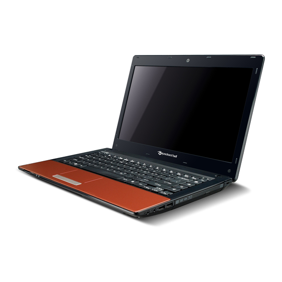
Your Acer Notebook tour Front View Icon Item Description Webcam Web camera for video communication (for selected models). Microphone Internal microphone for recording sound. Display screen Also called Liquid-Crystal Display (LCD), displays computer output. Indicates when the hard disk drive is active. Communication Indicates the computer’s wireless connectivity indicator... -
Page 17: Closed Front View
Icon Item Description Power button Turns the computer on and off. Keyboard For entering data into your computer. Palmrest Comfortable support area for your hands when you use the computer. Click buttons (left The left and right buttons function like the left and right) and right mouse buttons. -
Page 18: Left View
Left View Icon Item Description DC-in jack Connects to an AC adapter Ventilation slots Enable the computer to stay cool, even after prolonged use. External display Connects to a display device (VGA) port (e.g. external monitor, LCD projector). Ethernet (RJ-45) Connects to an Ethernet 10/100-based port network. -
Page 19: Right View
Right View Item Description USB 2.0 ports Connect to USB 2.0 devices (e.g. USB mouse, USB camera). Optical drive Internal optical drive; accepts CDs or DVDs. Optical disk access Lights up when the optical drive is active. indicator Optical drive eject button Ejects the optical disk from the drive. -
Page 20: Indicators
Icon Item Description Battery bay Houses the computer's battery pack. Battery release Releases the battery for removal. latch Hard disk bay Houses the computer's hard disk (secured with screws). Memory Houses the computer's main memory. compartment Battery lock Locks the battery in position. Ventilation slots Enable the computer to stay cool, even after and cooling fan... -
Page 21: Touchpad Basics
TouchPad Basics The following items show you how to use the TouchPad: • Move your finger across the TouchPad (1) to move the cursor. • Press the left (2) and right (3) buttons located beneath the TouchPad to perform selection and execution functions. -
Page 22: Using The Keyboard
Using the Keyboard The keyboard has full-sized keys and an embedded numeric keypad, separate cursor, lock, Windows, function and special keys. Lock Keys and embedded numeric keypad The keyboard has two lock keys which you can toggle on and off. Lock key Description Caps Lock... -
Page 23: Windows Keys
Windows Keys The keyboard has two keys that perform Windows-specific functions. Description Windows key Pressed alone, this key has the same effect as clicking on the Windows Start button; it launches the Start menu. It can also be used with other keys to provide a variety of functions: : Open or close the Start menu <... -
Page 24: Hot Keys
Hot Keys The computer employs hotkeys or key combinations to access most of the computer’s controls like screen brightness, volume output and the BIOS utility. To activate hot keys, press and hold the <Fn> key before pressing the other key in the hotkey combination. Hotkey Icon Function... - Page 25 Hotkey Icon Function Description Social Networking Opens Facebook Login screen. <Fn> + <Pg Up> Page Up Scrolls the page up. <Fn> + <Pg Dn> Page Down Scrolls the page down. <Fn> + <Home> Home Scrolls to the top of the page. <Fn>...
-
Page 26: Hardware Specifications And Configurations
Hardware Specifications and Configurations Processor Item Specification • Intel Calpella (Discrete/UMA: Arrandale with Gfx) • Intel PCH: HM55 (4MB SPI ROM) Type Intel Mobile Memron uPGA CPU Package Micro uPGA-478 Package Power 65 Watts On-die Cache 4MB L2 cache Front Side Bus 667/800/1066MHz Processor Specifications Cache... - Page 27 Item Specification Features • Flash ROM 4MB • Support ISIPP • Support Acer UI • Support multi-boot • Suspend to RAM (S3)/Disk (S4) • Various hot-keys for system control • Support SMBIOS 2.3, PCI2.2. • Refer to Acer BIOS specification. •...
- Page 28 Item Specification Feature Support for 10/100/1000 Onboard LAN Item Specification Manufacturer Broadcom 57780KMLG for GIGA LAN • Integrated 10/100/10000BASE-T transceiver • Automatic MDI crossover function • PCIe V1.1 compliant • 10/100/10000BASE-T full -duplex/half -duplex MAC • Receive side scaling(RSS) for multicore processors •...
- Page 29 Hard Disk Drive Interface Item Specification Vendor & Model Seagate HGST Toshiba Western Digital Name Capacity (MB) 160, 250, 320, 160, 250, 160, 250, 160, 250, 320, 320, 500 320, 500 500, 640 Bytes per sector Data heads Drive Format Disks Spindle speed 5400...
- Page 30 Super-Multi Drive Module Item Specification Vendor & model HLDS GT20N Sony AD7580S name Performance With CD Diskette With DVD Diskette With CD Diskette With DVD Diskette Specification Transfer rate (MB/ Sustained: Sustained: Sustained: Sustained: sec) 3,600 KB/s (24x) 11.08 Mbytes/s 1,571 (typical) 10,993 (typical) max.
- Page 31 Item Specification Features • High Definition Audio Codec • Single Analogue MIC • 2.0 Watt speaker/5cc chamber/speaker size 18 phi, x2 • Headphone-out w/o SPDIF-out Power and Keyboard Controller Item Specification Controller GP8T Type; 358.27mm x 113.44mm x 4.9mm Features •...
- Page 32 LCD 15.6” Item Specification Vendor/model name AUO/CPT/CMO/Samsung/LCD/INL Screen Diagonal (mm) 15.6 inches Display resolution (pixels) 1366 x 768 WXGA Clare Pixel Pitch 0.204 x 0.204 Display Mode Normal Typical White Luminance (cd/m (also called Brightness) Contrast Ratio 500 typical Response Time (Optical Rise Time/Fall Time) msec Luminance Uniformity 1.25 max...
-
Page 33: System Utilities
Chapter 2 System Utilities BIOS Setup Utility The BIOS Setup Utility is a hardware configuration program built into your computer’s BIOS (Basic Input/ Output System). Your computer is already properly configured and optimized, and you do not need to run this utility. However, if you encounter configuration problems, you may need to run Setup. -
Page 34: Packard Bell Easynote Tm86/Tm87/Tm89 Bios
Packard Bell EasyNote TM86/TM87/TM89 BIOS Information The Information screen displays a summary of the computer hardware information. I n s y d e H 2 0 S e t u p U t i l i t y R e v . 3 . 5... -
Page 35: Main
Main The Main screen allows the user to set the system time and date as well as enable and disable boot options and recovery. I n s y d e H 2 0 S e t u p U t i l i t y R e v. - Page 36 Parameter Description Format/Option Display Mode Control the graphics display mode. Options: Integrated Graphics, Discrete Note: Switchable Graphics is displayed as an option if Graphics or Switchable supported by the system. Graphics Chapter 2...
-
Page 37: Security
Security The Security screen contains parameters that help safeguard and protect your computer from unauthorized use. I n s y d e H 2 0 S e t u p U t i l i t y R e v . 3 . 5 Information Main Security... -
Page 38: Setting A Password
Setting a Password Follow these steps as you set the user or the supervisor password: Use the ↑ and ↓ keys to highlight the Set Supervisor Password parameter and press the Enter key. The Set Supervisor Password box appears: S e t S u p e r v i s o r P a s s w o r d E n t e r N e w P a s s w o r d C o n f i r m N e w P a s s w o r d Type a password in the “Enter New Password”... -
Page 39: Changing A Password
Changing a Password Use the ↑ and ↓ keys to highlight the Set Supervisor Password parameter and press the Enter key. The Set Password box appears. S e t S u p e r v i s o r P a s s w o r d E n t e r C u r r e n t P a s s w o r d E n t e r N e w P a s s w o r d C o n f i r m N e w P a s s w o r d... -
Page 40: Boot
Boot This menu allows the user to decide the order of boot devices to load the operating system. Bootable devices includes the USB diskette drives, the onboard hard disk drive and the DVD drive in the module bay. Select Boot Devices to select specific devices to support boot. I n s y d e H 2 0 S e t u p U t i l i t y R e v . -
Page 41: Exit
Exit The Exit screen allows you to save or discard any changes you made and quit the BIOS Utility. I n s y d e H 2 0 S e t u p U t i l i t y R e v. -
Page 42: Bios Flash Utilities
BIOS Flash Utilities The BIOS Flash memory update is required for the following conditions: • New versions of system programs • New features or options • Restore a BIOS when it becomes corrupted. Use the Flash utility to update the system BIOS Flash ROM. NOTE: If you do not have a crisis recovery diskette at hand, then you should create a Crisis Recovery Diskette before you use the Flash utility. -
Page 43: Dos Flash Utility
DOS Flash Utility Perform the following steps to use the DOS Flash Utility: Press F2 during boot to enter the Setup Menu. Select Boot Menu to modify the boot priority order, for example, if using USB HDD to Update BIOS, move USB HDD to position 1. - Page 44 In flash BIOS, the message Please do not remove AC Power Source displays. NOTE: If the AC power is not connected, the following message displays. Plug in the AC power to continue. Flash is complete when the message Flash programming complete displays. Chapter 2...
-
Page 45: Winflash Utility
WinFlash Utility Perform the following steps to use the WinFlash Utility: Double-click the WinFlash executable. Click OK to begin the update. A progress screen displays. Chapter 2... -
Page 46: Remove Hdd/Bios Password Utilities
Remove HDD/BIOS Password Utilities This section provides you with details about removing HDD/BIOS password: Remove HDD Password: If you key in the wrong HDD password three times, an error is generated. To reset the HDD password, perform the following steps: After the error is displayed, select the Enter Unlock Password option on the screen. - Page 47 Removing BIOS Passwords To clear the User or Supervisor passwords, open the DIMM door and use a metal instrument to short the RTC_RST point. Cleaning BIOS Passwords To clean the User or Supervisor passwords, perform the following steps: From a DOS prompt, execute clnpwd.exe Press 1 or 2 to clean the desired password shown on the screen.
-
Page 48: Using Boot Sequence Selector
Using Boot Sequence Selector The Boot Sequence Selector allows the boot order to be changed without accessing the BIOS. To use Boot Sequence Selector, perform the following steps: Enter into DOS. Execute BS.exe to display the usage screen. Select the desired boot sequence by entering the corresponding sequence. For example, enter BS2 to change the boot sequence to HDD | CD ROM | LAN | Floppy. -
Page 49: Using Dmitools
Using DMITools The DMI (Desktop Management Interface) Tool copies BIOS information to EEPROM to be used in the DMI pool for hardware management. When the BIOS displays Verifying DMI pool data it is checking that the table correlates with the hardware before sending to the operating system (Windows, etc.). -
Page 50: Using The Lan Mac Eeprom Utility
Using the LAN MAC EEPROM Utility You can use the MAC.BAT utility to write the MAC.CFG file to the EEPROM under DOS mode. Use a text editor (for example: Notepad) to open the MAC.CFG file. You can see the MAC.CFG contents as below: WriteData = ‘001122334455' MAC value... -
Page 51: Machine Disassembly And Replacement
Chapter 3 Machine Disassembly and Replacement IMPORTANT: The outside housing and color may vary from the mass produced model. This chapter contains step-by-step procedures on how to disassemble the notebook computer for maintenance and troubleshooting. Disassembly Requirements To disassemble the computer, you need the following tools: Wrist grounding strap and conductive mat for preventing electrostatic discharge •... -
Page 52: Pre-Disassembly Instructions
Pre-disassembly Instructions Before proceeding with the disassembly procedure, make sure that you do the following: 1. Turn off the power to the system and all peripherals. 2. Unplug the AC adapter and all power and signal cables from the system. 3. -
Page 53: Disassembly Process
Disassembly Process IMPORTANT: The LCD Module cannot be disassembled outside of factory conditions. If any part of the LCD Module is faulty, such as the camera, antenna or LCD panel, the whole module must be replaced. The disassembly process is divided into the following stages: External module disassembly •... -
Page 54: External Module Disassembly Process
External Module Disassembly Process IMPORTANT: The outside housing and color may vary from the mass produced model. External Modules Disassembly Flowchart The flowchart below gives you a graphic representation of the external module disassembly sequence and instructs you on the components that need to be removed during servicing. For example, if you want to remove the keyboard, you must first remove the switch board. -
Page 55: Removing The Battery Pack
Removing the Battery Pack 1. Turn computer over. Slide the battery lock in the direction shown. 2. Slide and hold the battery release latch to the release position (1), then lift out the battery pack from the main unit (2). NOTE: The battery has been highlighted with a yellow oval as shown in the above image. -
Page 56: Removing The Sim Card
Removing the SIM Card 1. See “Removing the Battery Pack” on page 45. 2. Push the SIM card all the way in to eject it. 3. Pull it out from the slot. Chapter 3... -
Page 57: Removing The Sd Dummy Card
Removing the SD Dummy Card 1. Push the SD dummy card all the way in to eject it. 2. Pull it out from the slot. Chapter 3... -
Page 58: Removing The Optical Drive Module
Removing the Optical Drive Module 1. See “Removing the Battery Pack” on page 45. 2. Remove the screw securing the ODD module. Step Size Quantity Screw Type ODD Module M2.5*8 3. Pull the optical drive module out from the chassis. Chapter 3... - Page 59 4. Remove the two (2) screws securing the ODD bracket and remove the ODD bracket from the optical disk drive module. Step Size Quantity Screw Type ODD Bracket M2*3 5. Remove the ODD bezel by prying the top edge away and clear of the module. Chapter 3...
-
Page 60: Removing The Logic Lower Door
Removing the Logic Lower Door 1. Remove three (3) screws from the Logic Lower Door. Step Size Quantity Screw Type Logic Lower door M2.5*8 2. Lift the door beginning from the inner edge as shown. 3. Lift the door clear off the device, exposing the HDD, DIMM, and WLAN modules. Chapter 3... -
Page 61: Removing The 3G Module
Removing the 3G Module 1. Loosen one (1) screw on the 3G Cover. Step Size Quantity Screw Type 3G Cover M2.5*8 2. Lift the 3G Cover from the left edge first, then remove completely. 3. Remove the two (2) antenna cables from the 3G module. Chapter 3... - Page 62 4. Remove one (1) screw from the 3G module. 5. Lift the 3G card from the slot. Chapter 3...
-
Page 63: Removing The Dimm Module
Removing the DIMM Module 1. See “Removing the Logic Lower Door” on page 50. 2. Push out the release latches on both sides of the DIMM socket to release the DIMM module. 3. Remove the DIMM module. 4. Repeat steps 2 and 3 for the second DIMM module if present. Chapter 3... -
Page 64: Removing The Wlan Module
Removing the WLAN Module 1. See “Removing the Logic Lower Door” on page 50. 2. Disconnect the two (2) antenna cables from the WLAN Board. 3. Move the antenna away and remove the one (1) screw to release the WLAN Board. Step Size Quantity... - Page 65 4. Detach the WLAN Board from the WLAN socket. NOTE: When reattaching the antennas, ensure the cables are tucked into the chassis to prevent damage. Chapter 3...
-
Page 66: Removing The Hard Disk Drive Module
Removing the Hard Disk Drive Module 1. See “Removing the Logic Lower Door” on page 50. 2. Using the pull-tab, slide the HDD Module in the direction of the arrow to disconnect the interface. 3. Lift the HDD Module clear of the HDD bay. NOTE: To prevent damage to device, avoid pressing down on it or placing heavy objects on top of it. - Page 67 4. Remove the four (4) screws (two each side) securing the hard disk to the carrier. Step Size Quantity Screw Type HDD Carrier M3*3 5. Remove the HDD from the carrier. Chapter 3...
-
Page 68: Main Unit Disassembly Process
Main Unit Disassembly Process Main Unit Disassembly Flowchart Remove External Remove Modules before Keyboard proceeding Remove Upper Cover Lower Upper Cover Cover Remove Remove TouchPad Power Board Bracket Remove Mainboard Remove Remove Left Speaker USB Board Module Remove Thermal Module Remove Remove Right Speaker... - Page 69 Step Screw Quantity Part No. TouchPad Bracket M2*3 86.WJ802.004 Mainboard M2.5*5 86.WJ802.001 Thermal Module M1.98*3.0 86.WJ802.004 Chapter 3...
-
Page 70: Removing The Keyboard
Removing the Keyboard 1. Unlock the six (6) keyboard locks. 2. Pry up the centre of the Keyboard and rotate it upward away from the Upper Cover. 3. Turn the keyboard over on to the TouchPad area to expose the FPC connector. Chapter 3... - Page 71 4. Open the locking latch and disconnect the FPC from the mainboard. 5. Lift the keyboard clear of the Upper Cover. Chapter 3...
-
Page 72: Removing The Upper Cover
Removing the Upper Cover 1. See “External Module Disassembly Process” on page 44. 2. Turn the computer over. Remove the eleven (11) screws on the lower cover and five (5) screws from the battery bay. Step Size Quantity Screw Type Upper Cover (red M2.5*8 callout) - Page 73 3. Disconnect the following four (4) cables from the Mainboard. Chapter 3...
- Page 74 4. Release the locking latch on A and disconnect the 5. Pull the cable off the adhesive as shown. cable. 6. Release the locking latch on B and remove the cable as shown. 7. Release the locking latch on C and remove the 8.
- Page 75 9. Remove the seven (7) screws on the Upper Cover as shown. Step Size Quantity Screw Type Upper Cover M2.5*5 10. Starting at the top right side of the cover, pry apart the Upper and Lower Covers as shown. Work along the front edge of the casing to the left as shown, then lift the Upper Cover clear of the Lower Cover.
-
Page 76: Removing The Left Speaker Module
Removing the Left Speaker Module 1. See “Removing the Upper Cover” on page 62. 2. Locate the Left Speaker Module on the Upper Cover as shown. 3. Remove two (2) screws from the left speaker module. Step Size Quantity Screw Type Left Speaker M2*3 Module... -
Page 77: Removing The Right Speaker Module
Removing the Right Speaker Module 1. See “Removing the Upper Cover” on page 62. 2. Locate the Right Speaker Module on the Upper Cover as shown. 3. Remove the one (1) securing screw from the Right Speaker Module. Step Size Quantity Screw Type Right Speaker... - Page 78 5. Lift the Right Speaker Module clear of the upper cover. Chapter 3...
-
Page 79: Removing The Power Board
Removing the Power Board 1. See “Removing the Upper Cover” on page 62. 2. Turn the upper cover over. Pass the cable through the upper cover as shown. 3. Remove two (2) screws from the power board. Step Size Quantity Screw Type Power board M2*3... -
Page 80: Removing The Touchpad Bracket
Removing the TouchPad Bracket IMPORTANT: The TouchPad Board cannot be removed individually. To replace the TouchPad Board, replace the entire Upper Cover. 1. See “Removing the Upper Cover” on page 62. 2. Lift the FFC to detach the adhesive securing the cable to the Upper Cover. 3. - Page 81 4. Remove the one (1) screw from TouchPad bracket. Step Size Quantity Screw Type TouchPad Bracket M2*3 5. Pry the Touchpad bracket off the adhesive and remove it as shown. Chapter 3...
-
Page 82: Removing The Card Reader Board
Removing the Card Reader Board 1. See “Removing the Upper Cover” on page 62. 2. Unlock the mainboard to card reader cable connector. 3. Remove the cable from the chassis by pulling up on the adhesive. 4. Remove one (1) screw from the card reader board. Step Size Quantity... - Page 83 5. Lift the card reader board clear of the device. Chapter 3...
-
Page 84: Removing The Usb Board
Removing the USB Board 1. See “Removing the Upper Cover” on page 62. 2. Unlock the mainboard to USB cable connector. 3. Remove the cable from the chassis by pulling up on the adhesive. 4. Remove one (1) screw from the USB board. Step Size Quantity... - Page 85 5. Lift the USB board clear of the device. Chapter 3...
-
Page 86: Removing The Bluetooth Board
Removing the Bluetooth Board 1. See “Removing the Upper Cover” on page 62. 2. Pry the Bluetooth board from the adhesive. 3. Disconnect the mainboard to Bluetooth cable. 4. Lift the Bluetooth board away from the cable channel as shown. Chapter 3... -
Page 87: Removing The Mainboard
Removing the Mainboard 1. See “Removing the Upper Cover” on page 62. 2. Unlock the microphone cable connector and disconnect the cable. 3. Disconnect the LVDS cable. Chapter 3... - Page 88 4. Remove the one (1) securing screw from the Mainboard. Step Size Quantity Screw Type Mainboard M2.5*5 5. Without removing completely, lift the mainboard from the chassis from the right edge first. CAUTION: Do not remove the mainboard completely. The mainboard is still connected to the chassis. Chapter 3...
- Page 89 6. Carefully turn the mainboard over and place it on a clean, dust-free surface. 7. Disconnect the power cable. 8. Remove the mainboard from the chassis and turn it over. NOTE: Circuit boards >10 cm² have been highlighted with a yellow rectangle as shown in the previous image.
- Page 90 9. Remove the adhesive tape from the bluetooth cable. 10. Unlock the connector and disconnect the bluetooth to mainboard cable. Chapter 3...
-
Page 91: Removing The Thermal Module
Removing the Thermal Module 1. See “Removing the Upper Cover” on page 62. 2. See “Removing the Mainboard” on page 77. 3. Disconnect the fan cable. 4. Remove the four (4) securing screws (in reverse numerical order from screw 4 to screw 1) from the Thermal Module. - Page 92 5. Carefully lift the Thermal Module clear of the Mainboard. Chapter 3...
-
Page 93: Removing The Cpu
Removing the CPU IMPORTANT: The pins on the underside of the CPU are very delicate. If they are damaged, the CPU may malfunction. Place the CPU on a clean, dry surface when it is not installed. 1. See “Removing the Thermal Module” on page 81. 2. -
Page 94: Lcd Module Disassembly Process
LCD Module Disassembly Process LCD Module Disassembly Flowchart Remove LCD Assembly Remove LCD Bezel Remove Camera Module Remove Inverter Board Remove LCD Panel Remove Remove Remove LCD Brackets Microphone Antennas and FPC Cable Cable Screw List Step Screw Quantity Part No. LCD Bezel M2.5*6 86.WJ802.003... -
Page 95: Removing The Lcd Assembly
Removing the LCD Assembly 1. See “Removing the Upper Cover” on page 62. 2. Turn the device over and pass the black and white antenna cables through the lower cover. 3. Free the black and white antenna cables from the cable channel as shown. 4. - Page 96 5. Remove the LVDS cable from the cable channel. 6. Remove the adhesive tape from the black antenna cable and free the cable from the cable channel. Chapter 3...
- Page 97 7. Remove four (4) screws from the LCD assembly. Step Size Quantity Screw Type LCD assembly M2.5*8 8. Remove the LCD assembly from the lower cover. Chapter 3...
-
Page 98: Removing The Lcd Bezel
Removing the LCD Bezel 1. See “Removing the LCD Assembly” on page 85. 2. Remove the two (2) bezel screw caps and screws. Step Size Quantity Screw Type LCD Bezel M2.5*6 3. Starting from the bottom edge of the bezel, pry the bezel upwards and away from the panel. Work along the right side toward the top of the bezel, prying the covers apart. -
Page 99: Removing The Camera Module
Removing the Camera Module 1. See “Removing the LCD Assembly” on page 85. 2. Locate the Camera Module at the top of the LCD Module and disconnect the camera cable. 3. Remove the Camera from the module. Chapter 3... -
Page 100: Removing The Inverter Board
Removing the Inverter Board 1. See “Removing the LCD Assembly” on page 85. 2. Remove the adhesive tape from the inverter cables. 3. Remove one (1) screw from the inverter board. Step Size Quantity Screw Type Inverter Board M2.5*5 4. Using both hands, rotate the inverter board around the hook to free it from the panel. Chapter 3... - Page 101 5. Turn the board over and disconnect the cable. Chapter 3...
-
Page 102: Removing The Lcd Panel
Removing the LCD Panel 1. See “Removing the Camera Module” on page 89. 2. Remove the two (2) securing screws from the LCD Panel. Step Size Quantity Screw Type LCD Panel M2.5*6 3. Remove the adhesive tape from the cable and continue removing the cable from the channel. Chapter 3... - Page 103 4. Lift the LCD Panel clear of the module. Chapter 3...
-
Page 104: Removing The Lcd Brackets And Fpc Cable
Removing the LCD Brackets and FPC Cable 1. See “Removing the LCD Panel” on page 92. 2. Remove the six (6) securing screws (three on each side) from the LCD Panel brackets. Step Size Quantity Screw Type LCD Brackets M2*3 3. - Page 105 5. Disconnect the LVDS cable from the panel. Chapter 3...
-
Page 106: Removing The Microphone Cable
Removing the Microphone Cable 1. See “Removing the LCD Panel” on page 92. 2. Remove the cable bundle from the hinge channel. 3. Peel back the foil tabs and remove the microphone cable from the cable channel. 4. Continue removing the cable from the cable channel. Chapter 3... - Page 107 5. Lift the microphone set clear of the panel. Chapter 3...
-
Page 108: Removing The Antennas
Removing the Antennas 1. See “Removing the LCD Panel” on page 92. 2. Remove the black antenna from the cable channel. 3. Peel back the foil tabs and remove the cable from the cable channel. 4. Pry the antenna assembly clear of the device. Chapter 3... - Page 109 5. Remove the white antenna from the hinge channel. 6. Peel back the foil tabs and remove the cable from the cable channel. 7. Pry the antenna assembly clear of the device. Chapter 3...
-
Page 110: Lcd Module Reassembly Procedure
LCD Module Reassembly Procedure Replacing the Antennas 1. Adhere the white antenna assembly to the LCD cover. 2. Run the cable along the cable channel and fold over the foil tabs to secure the cable in place. 3. Run the white antenna along the hinge channel. Chapter 3... - Page 111 4. Adhere the black antenna assembly on the LCD cover. 5. Run the cable along the cable channel and fold over the foil tabs to secure the cable in place. 6. Run the black antenna cable along the cable channel. Chapter 3...
-
Page 112: Replacing The Microphone Cable
Replacing the Microphone Cable 1. Place the microphone set in the panel. 2. Fold the foil tab over to secure. 3. Fold over the foil tabs and continue running the 4. Run the cable bundle along the hinge channel. microphone cable along the cable channel indicated between the red callouts. -
Page 113: Replacing The Lcd Brackets And Fpc Cable
Replacing the LCD Brackets and FPC Cable 1. Connect the LVDS cable to the LCD panel. 2. Adhere the LVDS mylar to the LCD panel. 3. Attach the LCD brackets to the LCD Panel. Chapter 3... - Page 114 4. Replace six (6) securing screws (three on each side) of the LCD Panel brackets. Chapter 3...
-
Page 115: Replacing The Lcd Panel
Replacing the LCD Panel 1. Place the LCD Panel in the module. 2. Run the cable along the channel in the LCD Module as shown. 3. Apply the adhesive strip to hold the cable in place. 4. Secure the panel using two (2) securing screws. Chapter 3... -
Page 116: Replacing The Inverter Board
Replacing the Inverter Board 1. Place the LCD Panel in the module. 2. Run the cable along the channel in the LCD Module as shown. 3. Apply the adhesive strip to hold the cable in place. 4. Secure the panel using two (2) securing screws. Chapter 3... -
Page 117: Replacing The Camera Module
Replacing the Camera Module 1. Place the Camera in the module. 2. Connect the camera cable. Chapter 3... -
Page 118: Replacing The Lcd Bezel
Replacing the LCD Bezel 1. Replace the bezel and press down until there are no gaps between the bezel and the LCD Module. IMPORTANT: Ensure that the LCD cables pass through the hinge wells and are not trapped by the bezel. 2. -
Page 119: Replacing The Lcd Assembly
Replacing the LCD Assembly 1. Place the LCD assembly on the lower cover. 2. Secure the LCD assembly using four (4) screws. Chapter 3... - Page 120 3. Replace the adhesive tape and run the black antenna cable along the cable channel. 4. Near the left hinge, run the LVDS cable along the cable channel. Chapter 3...
- Page 121 5. Run the white antenna cable along the cable channel as shown. 6. Run the black antenna cables along the cable channel. 7. Pass the black and white antenna cables through the lower cover. Chapter 3...
-
Page 122: Main Module Reassembly Procedure
Main Module Reassembly Procedure Replacing the CPU IMPORTANT: The CPU has a Pin1 locator that must be positioned corresponding to the marker on the CPU socket. 1. Place the CPU into the CPU socket as shown, taking note of the Pin1 locator. Socket Pin1 Locator 2. -
Page 123: Replacing The Thermal Module
Replacing the Thermal Module IMPORTANT: Apply a suitable thermal grease and ensure all heat pads are in place before replacing the Thermal Module. The following thermal grease types are approved for use: Silmore GP50 • Honeywell • Jet Motor 7762 •... -
Page 124: Replacing The Mainboard
Replacing the Mainboard 1. Connect the Bluetooth to mainboard cable. 2. Apply the adhesive tape to the Bluetooth cable. 3. Place the mainboard on a clean, dust-free surface. Connect the power cable. NOTE: Ensure the I/O ports are positioned correctly through the casing. Chapter 3... - Page 125 4. Place the mainboard in the chassis, left edge first to line up the I/O ports. 5. Secure the one (1) securing screw on the Mainboard. Chapter 3...
- Page 126 6. Connect the LVDS cable and lock the connector. 7. Connect the microphone cable. Chapter 3...
-
Page 127: Replacing The Bluetooth Board
Replacing the Bluetooth Board 1. Run the bluetooth cable along the channel as shown. 2. Connect the mainboard to bluetooth cable. 3. Adhere the bluetooth board to the adhesive. Chapter 3... -
Page 128: Replacing The Usb Board
Replacing the USB Board 1. Place the USB board in the device. 2. Secure the one (1) screw on the USB board. 3. Connect the USB cable to the mainboard and lock the connector. Chapter 3... -
Page 129: Replacing The Card Reader Board
Replacing the Card Reader Board 1. Place the card reader board in the device. 2. Secure one (1) screw on the card reader board. 3. Connect the card reader cable and lock the connector. Chapter 3... -
Page 130: Replacing The Touchpad Bracket
Replacing the TouchPad Bracket 1. Replace the TouchPad bracket top edge first to engage the securing clips and press down firmly. 2. Replace the one (1) screw to secure the TouchPad Bracket to the Upper Cover. 3. Replace the TouchPad FFC and close the locking latch on the connector. Chapter 3... - Page 131 4. Replace the FFC and press down as indicated to secure it to the Upper Cover. Chapter 3...
-
Page 132: Replacing The Power Board
Replacing the Power Board 1. Place the power board in the chassis. Adhere the power board assembly as shown. 2. Secure two (2) screws on the power board. 3. Pass the power board cable through the upper cover. Adhere the power board cable as shown. Chapter 3... -
Page 133: Replacing The Right Speaker Module
Replacing the Right Speaker Module 1. Place the right speaker module in the chassis as shown. 2. Run the speaker cable along the channel. 3. Secure the one (1) securing screw on the Right Speaker Module. Chapter 3... -
Page 134: Replacing The Left Speaker Module
Replacing the Left Speaker Module 1. Place the module right side first on the Upper 2. Run the Speaker cable along the cable channel. Cover as shown. 3. Secure two (2) screws from the left speaker module. Chapter 3... -
Page 135: Replacing The Upper Cover
Replacing the Upper Cover 1. Place the Upper Cover on the Lower Cover as shown. 2. Secure the seven (7) screws on the Upper Cover as shown. Chapter 3... - Page 136 3. Connect the following cables to the Mainboard. 4. Connect D as shown. 5. Connect C as shown. Chapter 3...
- Page 137 6. Connect B as shown. 7. Connect A as shown. 8. Turn the computer over. Replace the eleven (11) screws on the lower cover and five (5) screws from the battery bay. Chapter 3...
-
Page 138: Replacing The Keyboard
Replacing the Keyboard 1. Connect the Keyboard FFC to the Mainboard and close the locking latch to secure the cable in place. 2. Replace the Keyboard by first lining up the bottom edge. Press down firmly to lock. Chapter 3... -
Page 139: Replacing The Hard Disk Drive Module
Replacing the Hard Disk Drive Module 1. Place the HDD in the HDD carrier. 2. Replace the four (4) screws (two each side) to secure the carrier. 3. Insert the HDD, as indicated and lower it into 4. Slide the HDD in the direction of the arrow to place. -
Page 140: Replacing The Wlan Module
Replacing the WLAN Module 1. Insert the WLAN Module into the WLAN socket. 2. Replace the one (1) screw to secure the module. 3. Connect the two (2) Antenna cables to the module. NOTE: The black cable connects to the upper terminal (MAIN) and the white cable to the lower terminal (MAIN). -
Page 141: Replacing The Dimm Modules
Replacing the DIMM Modules 1. Insert the DIMM Module in place. 2. Press down to lock the DIMM module in place. 3. Repeat steps for the second DIMM module if present. Chapter 3... -
Page 142: Replacing The 3G Module
Replacing the 3G Module 1. Insert the 3G card into the slot. 2. Replace one (1) screw from the 3G module. 3. Connect two (2) antenna cables. Chapter 3... - Page 143 4. Line up the right edge of the 3G cover and replace. 5. Secure one (1) screw on the 3G Cover. Chapter 3...
-
Page 144: Replacing The Logic Lower Door
Replacing the Logic Lower Door 1. Replace the door by first lining up the top edge as shown. 2. Secure three (3) screws on the lower cover. Chapter 3... -
Page 145: Replacing The Odd Module
Replacing the ODD Module 1. Press the bezel into the tray, bottom edge first, to 2. Place the bracket on the ODD module. secure it to the ODD Module. 3. Secure the ODD bracket with the two (2) screws. 4. Push the ODD Module into the ODD bay until it is 5. -
Page 146: Replacing The Sd Dummy Card
Replacing the SD Dummy Card 1. Insert the SD Dummy Card into the slot as shown. 2. Push until the card clicks into place and is flush with the casing. Chapter 3... -
Page 147: Replacing The Sim Card
Replacing the SIM Card 1. Insert the SIM Card into the slot as shown. 2. Push until the card clicks into place and is flush with the casing. Chapter 3... -
Page 148: Replacing The Battery
Replacing the Battery 1. Slide and hold the battery release latch to the 2. Slide the battery lock in the direction shown to release position (1), insert the battery pack and secure the battery in place. press down (2). Chapter 3... -
Page 149: Troubleshooting
Chapter 4 Troubleshooting Common Problems Use the following procedure as a guide for computer problems. NOTE: The diagnostic tests are intended to test only Acer products. Non-Acer products, prototype cards, or modified options can give false errors and invalid system responses. Obtain the failing symptoms in as much detail as possible. -
Page 150: Power On Issue
Power On Issue If the system doesn’t power on, perform the following actions one at a time to correct the problem. Do not replace a non-defective FRUs: Computer Shutsdown Intermittently If the system powers off at intervals, perform the following actions one at a time to correct the problem. Check the power cable is properly connected to the computer and the electrical outlet. -
Page 151: No Display Issue
No Display Issue If the Display doesn’t work, perform the following actions one at a time to correct the problem. Do not replace a non-defective FRUs: No POST or Video If the POST or video doesn’t display, perform the following actions one at a time to correct the problem. Make sure that the internal display is selected. -
Page 152: Random Loss Of Bios Settings
Abnormal Video Display If video displays abnormally, perform the following actions one at a time to correct the problem. Reboot the computer. If permanent vertical/horizontal lines or dark spots display in the same location, the LCD is faulty and should be replaced. See “Disassembly Process” on page 43. If extensive pixel damage is present (different colored spots in the same locations on the screen), the LCD is faulty and should be replaced. -
Page 153: Lcd Failure
LCD Failure If the LCD fails, perform the following actions one at a time to correct the problem. Do not replace a non- defective FRUs: Built-In Keyboard Failure If the built-in Keyboard fails, perform the following actions one at a time to correct the problem. Do not replace a non-defective FRUs: Chapter 4... -
Page 154: Touchpad Failure
TouchPad Failure If the TouchPad doesn’t work, perform the following actions one at a time to correct the problem. Do not replace a non-defective FRUs: Internal Speaker Failure If the internal Speakers fail, perform the following actions one at a time to correct the problem. Do not replace a non-defective FRUs: Chapter 4... -
Page 155: Sound Problems
Sound Problems If sound problems are experienced, perform the following actions one at a time to correct the problem. Reboot the computer. Navigate to Start Control Panel System and Maintenance System Device Manager. Check the Device Manager to determine that: •... -
Page 156: Hdd Not Operating Correctly
HDD Not Operating Correctly If the HDD does not operate correctly, perform the following actions one at a time to correct the problem. Disconnect all external devices. Run a complete virus scan using up-to-date software to ensure the computer is virus free. Run the Windows 7 Startup Repair Utility: insert the Windows 7 Operating System DVD in the ODD and restart the computer. -
Page 157: Odd Failure
ODD Failure If the ODD fails, perform the following actions one at a time to correct the problem. Do not replace a non- defective FRUs: ODD Not Operating Correctly If the ODD exhibits any of the following symptoms it may be faulty: •... - Page 158 Double-click lDE ATA/ATAPI controllers. If a device displays a down arrow, right-click on the device and click Enable. Double-click DVD/CD-ROM drives. If the device displays a down arrow, right-click on the device and click Enable. Check that there are no yellow exclamation marks against the items in lDE ATA/ATAPI controllers. If a device has an exclamation mark, right-click on the device and uninstall and reinstall the driver.
- Page 159 Double-click IDE ATA/ATAPI controllers, then right-click ATA Device 0. Click Properties and select the Advanced Settings tab. Ensure that the Enable DMA box is checked and click OK. Repeat for the other ATA Devices shown if applicable. Drive Not Detected If Windows cannot detect the drive, perform the following actions one at a time to correct the problem.
-
Page 160: Wireless Function Failure
Wireless Function Failure If the WLAN fails, perform the following actions one at a time to correct the problem. Do not replace a non- defective FRUs: Thermal Unit Failure If the Thermal Unit fails, perform the following actions one at a time to correct the problem. Do not replace a non-defective FRUs: Chapter 4... -
Page 161: External Mouse Failure
External Mouse Failure If an external Mouse fails, perform the following actions one at a time to correct the problem. Try an alternative mouse. If the mouse uses a wireless connection, insert new batteries and confirm there is a good connection. See the mouse user manual. -
Page 162: Intermittent Problems
Intermittent Problems Intermittent system hang problems can be caused by a variety of reasons that have nothing to do with a hardware defect, such as: cosmic radiation, electrostatic discharge, or software errors. FRU replacement should be considered only when a recurring problem exists. When analyzing an intermittent problem, do the following: Run the advanced diagnostic test for the system board in loop mode at least 10 times. -
Page 163: Post Codes
Post Codes These tables describe the POST codes and descriptions during the POST. Post Code Range Phase POST Code Range 0x01 - 0x0F 0x70 - 0x9F 0x40 - 0x6F 0x10 - 0x3F 0xA0 - 0xBF 0xC0 - 0xCF 0x51 – 0x55 0xE1 –... - Page 164 PEI Phase POST Code Table: Functionality Name (Include\ Post Phase Description PostCode.h) Code PEI_SIO_INIT Super I/O Initialization PEI_CPU_REG_INIT CPU Early Initialization PEI_CPU_AP_INIT Multi-processor Early Initial PEI_CPU_HT_RESET HyperTransport Initialization PEI_PCIE_MMIO_INIT PCIE MMIO BAR Initialization PEI_NB_REG_INIT North Bridge Early Initialization PEI_SB_REG_INIT South Bridge Early Initialization PEI_PCIE_TRAINING PCIE Training PEI_TPM_INIT...
- Page 165 DXE Phase POST Code Table: Functionality Name (Include\ Phase PostCode Description PostCode.h) DXE_TCGDXE TPM initial in DXE DXE_SB_SPI_INIT South bridge SPI initialization DXE_CF9_RESET Setup Reset service DXE_SB_SERIAL_GPIO_INIT South bridge Serial GPIO initialization DXE_SMMACCESS Setup SMM ACCE SS service DXE_NB_INIT North bridge Middle initialization DXE_SIO_INIT Super I/O DXE initialization DXE_LEGACY_REGION...
- Page 166 BDS Phase POST Code Table: Functionality Name (Include\ Post Phase Description PostCode.h) Code BDS_ENTER_BDS Enter BDS entry BDS_INSTALL_HOTKEY Install Hotkey service BDS_ASF_INIT ASF Initialization BDS_PCI_ENUMERATION_START PCI enumeration BDS_BEFORE_PCIIO_INSTALL PCI resource assign complete BDS_PCI_ENUMERATION_END PCI enumeration complete BDS_CONNECT_CONSOLE_IN Keyboard Controller, Keyboard and Mouse initialization BDS_CONNECT_CONSOLE_OUT Video device initialization...
- Page 167 Functionality Name (Include\ Post Phase Description PostCode.h) Code BDS_RECOVERY_START_FLASH Fast Recovery Start Flash. NOTE: The color bar items indicate 3rd party related functions that are platorm dependent. PostBDS POST Code Table Functionality Name (Include\ Post Phase Description PostCode.h) Code POST_BDS_NO_BOOT_DEVICE POST_BDS No Boot Device POST_BDS_START_IMAGE...
- Page 168 Functionality Name (Include\ Post Phase Description PostCode.h) Code SMM_ACPI_DISABLE_START 0xA8 OS call ACPI disable function SMM_ACPI_DISABLE_END 0xA9 ACPI disable function complete InsydeH2ODDT Debugger POST Code Table Functionality Name PostCode Description (Include\ PostCode.h) Used by Insyde debugger 0x0D Waiting for device connect Used by Insyde debugger 0xD0 Waiting for device connect...
-
Page 169: Jumper And Connector Locations
Chapter 5 Jumper and Connector Locations Top View Item Description Item Description JLVDS1 Connect to LED / CCFL Panel JLED1 Connect to Powerboard (FFC) JSPK2 Connect to Left Speaker JLED2 Connect to Powerboard (FFC) JSPK1 Connect to Right Speaker Connect to internal MIC JKB1 Connect to Keyboard SW2/SW3... -
Page 170: Bottom View
Bottom View Item Description Item Description PJP2 Connect to Battery JHP1 Connect to external headphone PJP1 DC-IN jack JBT1 Connect to BT JDIMM1/ DDR3 memory socket JHDD1 Connect to SATAHDD JDIMM2 JCRT1 Connect to external CRT JODD1 Connect to SATAODD JRJ45 RJ45 LAN Connect to 3G board... -
Page 171: Usb/B Board
USB/B Board ITEM DESCRIPTION JUSB1/JUSB2 USB Connector Power Board ITEM DESCRIPTION ITEM DESCRIPTION LED1 For NEW70 ON/OFF LED LED9 For NEW50 WWAN LED LED2 For NEW80 ON/OFF LED LED10 For NEW70 WLAN LED LED3 For NEW90 ON/OFF LED LED11 For NEW50 POWER LED LED4 For NEW70 MEDIA LED LED12... -
Page 172: 3G/B Board
3G/B Board ITEM DESCRIPTION JMINI2 Connect to WWAN JSIM1 SIM card connector Connector to MB (FFC) CR/B Board ITEM DESCRIPTION JREAD1 Card reader connector Chapter 5... -
Page 173: Clearing Password Check And Bios Recovery
This section provides you with the standard operating procedures of clearing password and BIOS recovery for the Packard Bell EasyNote TM86/TM87/TM89. The machine provides one Hardware Open Gap on main board for clearing password check, and one Hotkey for enabling BIOS Recovery. -
Page 174: Bios Recovery By Crisis Disk
BIOS Recovery by Crisis Disk BIOS Recovery Boot Block: BIOS Recovery Boot Block is a special block of BIOS. It is used to boot up the system with minimum BIOS initialization. Users can enable this feature to restore the BIOS firmware to a successful one once the previous BIOS flashing process failed. -
Page 175: Fru (Field Replaceable Unit) List
FRU (Field Replaceable Unit) List This chapter gives you the FRU (Field Replaceable Unit) listing in global configurations of Packard Bell EasyNote TM86/ TM87/TM89. Refer to this chapter whenever ordering for parts to repair or for RMA (Return Merchandise Authorization). -
Page 176: Easynote Exploded Diagrams
EasyNote Exploded Diagrams Main Assembly Description Acer P/N Description Acer P/N Keyboard KB.I170G.083 3G Module Upper Cover 60.WJ802.001 Card Reader 55.WJ802.002 Mainboard MB.WJU02.001 USB Board 55.WJ802.003 KC.52001.DMP Lower Cover 60.WJ802.002 Thermal Module 60.WJ802.006 Chapter 6... -
Page 177: Upper Assembly
Upper Assembly Description Acer P/N Touchpad Bracket 33.WJ802.001 Touchpad Cable 50.WJ802.003 Touchpad Board Touchpad Assy Power Board 55.WJ802.001 Speaker Right 23.WJ802.002 Speaker Left 23.WJ802.003 Upper Cover 60.WJ802.001 Chapter 6... -
Page 178: Lcd Assembly
LCD Assembly Description Acer P/N Description Acer P/N LCD Bezel 60.WJ802.004 LCD Panel LK.15605.010 LCD Bracket (L) 33.WJ802.004 LVDS Cable 50.WJ802.006 Antenna Cable 50.WJ802.004 Antenna Cable 50.WJ802.005 (Main) (Aux) Microphone Cable 23.WJ802.001 Camera Module 57.WJ802.001 LCD Bracket (R) 33.WJ802.004 LCD Cover 60.BHN02.001 Chapter 6... -
Page 179: Fru List
FRU List CATEGORY Acer Description AcerPN BOARD FOXCONN BLUETOOTH BRM 2046 BT2.1 BH.21100.004 (T60H928.33) F/W:861 FOXCONN BLUETOOTH ATH AR3011 BH.21100.005 POWER BOARD 55.WJ802.001 CARD READER BOARD 55.WJ802.002 USB BOARD 55.WJ802.003 FOXCONN WIRELESS LAN ATHEROS HB93 2X2 NI.23600.062 BGN (HM) LITEON WIRELESS LAN ATHERIS HB93 2X2 BGN NI.23600.063 (HM) WN6602AH LITEON WIRELESS LAN REALTEK 8192SE BGN... - Page 180 CATEGORY Acer Description AcerPN POWER CORD ARGENTINA 3 PIN 27.APV02.001 CASE/COVER/BRACKET ASSEMBLY UPPER CASE ASSY, INCL. TP/TP MYLAR-SLIVER 60.WJ802.001 UPPER CASE ASSY, INCL. TP/TP MYLAR-RED 60.WJL02.001 UPPER CASE ASSY, INCL. TP/TP MYLAR-BLUE 60.WJU02.001 LOWER CASE 60.WJ802.002 LOGIC LOWER DOOR 42.WJ802.001 3G DOOR 42.WJ802.002 TP BRACKET...
- Page 181 CATEGORY Acer Description AcerPN KEYBOARD Keyboard GATEWAY GP-7Tv2 SJM51 Internal 17 KB.I170G.083 Standard 103KS White US International Keyboard GATEWAY GP-7Tv2 SJM51 Internal 17 KB.I170G.068 Standard 103KS White Greek Keyboard GATEWAY GP-7Tv2 SJM51 Internal 17 KB.I170G.059 Standard 103KS White Arabic Keyboard GATEWAY GP-7Tv2 SJM51 Internal 17 KB.I170G.063 Standard 103KS White Chinese Keyboard GATEWAY GP-7Tv2 SJM51 Internal 17...
- Page 182 CATEGORY Acer Description AcerPN Keyboard GATEWAY GP-7Tv2 SJM51 Internal 17 KB.I170G.062 Standard 104KS White CZ/SK Keyboard GATEWAY GP-7Tv2 SJM51 Internal 17 KB.I170G.061 Standard 104KS White Brazilian Portuguese LCD COVER IMR PB-SLIVER 60.BHN02.001 LCD COVER IMR PB-RED 60.BHY02.001 LCD COVER IMR PB-BLUE 60.BJ202.001 LCD BEZEL FOR W/CMOS PB 60.BHN02.002...
- Page 183 CATEGORY Acer Description AcerPN HEATSINK THERMAL MOUDLE-UMA 60.WJ802.006 THERMAL MOUDLE-PARK 60.WJ702.001 THERMAL MOUDLE-MADISON 60.WJF02.001 SPEAKER MIC SET 23.WJ802.001 SPEAKER R 23.WJ802.002 SPEAKER L 23.WJ802.003 MISCELLANEOUS LCD SCREW PAD 47.WJ802.001 CPU/PROCESSOR CPU INTEL CORE I5 520M 2.4G 3M KC.52001.DMP CPU INTEL CORE I5 430M PGA 2.26G ARD, UP TO KC.43001.DMP SC 2.53G, 3M L3 CPU INTEL CORE I3 330M PGA 2.13G 35W...
- Page 184 CATEGORY Acer Description AcerPN HDD SEAGATE 2.5" 5400RPM 500GB ST9500325AS KH.50001.011 WYATT SATA LF F/W:0001SDM1 HDD HGST 2.5" 5400RPM 500GB KH.50007.010 HTS545050B9A300 PANTHER B SATA LF F/W:C60F DISK IMBALANCE CRITERIA = 0.014G-CM HDD SEAGATE 2.5" 5400RPM 160GB ST9160314AS KH.16001.042 WYATT SATA LF F/W:0001SDM1 HDD SEAGATE 2.5"...
- Page 185 CATEGORY Acer Description AcerPN BATTERY BATTERY SANYO AS10D LI-ION 3S2P SANYO 6 BT.00603.111 CELL 4400MAH MAIN COMMON ID:AS10D31 BATTERY SAMSUNG AS10D LI-ION 3S2P BT.00606.008 SAMSUNG 6 CELL 4400MAH MAIN COMMON ID:AS10D61 BATTERY SIMPLO AS10D LI-ION 3S2P PANASONIC BT.00607.125 6 CELL 4400MAH MAIN COMMON ID:AS10D71 BATTERY SIMPLO AS10D LI-ION 3S2P SAMSUNG 6 BT.00607.127 CELL 4400MAH MAIN COMMON ID:AS10D...
-
Page 186: Screw List
Screw List CATEGORY DESCRIPTION Acer PN SCREW SCREW 2.5D 5L K 5.5D ZK NL CR3 86.WJ802.001 SCREW 2.45D 8.0L K 5.5D 0.8T ZK NL 86.WJ802.002 SCREW 2.5D 6L K 5.5D NI NL 86.WJ802.003 SCREW 1.98D 3.0L K 4.6D 0.8T ZK NL 86.WJ802.004 SCREW 3.0D 3.0L K 4.9D NI 86.WJ802.005... - Page 187 Chapter 6...
-
Page 188: Model Definition And Configuration
Appendix A Model Definition and Configuration Appendix A... -
Page 189: Packard Bell Easynote Tm86
Packard Bell EasyNote TM86 Model Acer Part No Country Description ENTM86- LX.BJX02.002 EMEA France ENTM86-434G64Bn W7HP64BTFR1 434G64Bn N11PGV2H1GBCsk_3V3 2*2G/640/ 6L2.2/5R/CB_bgn_1.3C_GEs_FR51 EASYNOTE_TM86-JO-228FR ENTM86- S2.BJX02.002 ENTM86-334G50Mn W7HP64BWW2 334G50Mn N11PGV2H1GBCsk_3V3 2*2G/500_L/ BT/6L2.2/5R/CB_bgn_1.3C_GEs_EN11 ENTM86- LX.BJX02.001 EMEA France ENTM86-434G64Mn W7HP64BTFR1 434G64Mn N11PGV2H1GBCsk_3V3 2*2G/640/ 6L2.2/5R/CB_bgn_1.3C_GEs_FR51 EASYNOTE_TM86-JO-205FR ENTM86- S2.BJX02.001... - Page 190 Memory Memory Model Acer Part No VRAM 1 Chip ENTM86- LX.BJX02.002 Ci5430M NLED15.6 N11PG 1G-DDR3 SO2GBII SO2GBIII 434G64Bn WXGAG (64*16*8) ENTM86- S2.BJX02.002 Ci3330M NLED15.6 N11PG 1G-DDR3 SO2GBII SO2GBIII 334G50Mn WXGAG (64*16*8) ENTM86- LX.BJX02.001 Ci5430M NLED15.6 N11PG 1G-DDR3 SO2GBII SO2GBIII 434G64Mn WXGAG (64*16*8) ENTM86-...
- Page 191 Memory Memory Media Model Acer Part No 1(GB) 2(GB) Processor ENTM86- LX.BHP02.001 N320GB NSM8XS 334G32Mn 5.4KS ENTM86- S2.BHP02.003 N320GB NSM8XS 433G32Mn 5.4KS ENTM86- S2.BHP02.002 N250GB NSM8XS 334G25Mn 5.4KS ENTM86- S2.BHP02.001 N160GB NSM8XS 332G16Mn 5.4KS ENTM86- LX.BHN02.002 N320GB NSM8XS 334G32Mn 5.4KS ENTM86- LX.BHN02.001 N500GB...
-
Page 192: Packard Bell Easynote Tm87
Packard Bell EasyNote TM87 Model Acer Part No Country Description ENTM87- S2.BJY02.002 ENTM87-434G64Bn W7HP64BWW2 434G64Bn N11PGV2H1GBCrk_3V3 2*2G/640/BT/ 6L2.2/5R/CB_bgn_1.3C_GEr_EN11 ENTM87- LX.BJY02.001 EMEA France ENTM87-334G32Mn W7HP64BTFR1 334G32Mn N11PGV2H1GBCrk_3V3 2*2G/320/BT/ 6L2.2/5R/CB_bgn_1.3C_GEr_FR51 EASYNOTE_TM87-CP-200FR ENTM87- S2.BJY02.001 ENTM87-332G32Mn W7HP64BWW2 332G32Mn N11PGV2H1GBCrk_3V3 1*2G/320/ 6L2.2/5R/CB_bgn_1.3C_GEr_EN11 ENTM87- LX.BJ002.003 EMEA... - Page 193 Memory Memory Model Acer Part No VRAM 1 Chip ENTM87- S2.BJ002.001 Ci3330M NLED15.6 PARK 512M- SO1GBI SO2GBIII 333G25Bn WXGAG DDR3 II10 (64*16*4) ENTM87- LX.BJ002.001 Ci5520M NLED15.6 PARK 512M- SO2GBI SO2GBIII 524G50Mn WXGAG DDR3 II10 (64*16*4) ENTM87- S2.BJ00C.001 Ci3330M NLED15.6 PARK 512M- SO2GBI 332G16Mn...
- Page 194 Extra Wireless VOIP Model Acer Part No Card Reader Bluetooth LAN1 Phone ENTM87- LX.BJ002.002 5 in 1-Build in 3rd WiFi 2x2 334G50Mn ENTM87- S2.BJ002.001 5 in 1-Build in 3rd WiFi 2x2 333G25Bn ENTM87- LX.BJ002.001 5 in 1-Build in 3rd WiFi 2x2 BT 2.1 524G50Mn ENTM87-...
-
Page 195: Packard Bell Easynote Tm89
Packard Bell EasyNote TM89 Model Acer Part No Country Description ENTM89- S2.BJZ02.001 ENTM89-522G16Mn W7HP64BWW2 522G16Mn N11PGV2H1GBCbk_3V3 1*2G/160/6L2.2/ 5R/CB_bgn_1.3C_GEb_EN11 ENTM89- S2.BJ302.001 ENTM89-332G16Mn W7HP64BWW2 332G16Mn PARK_XT512Cbb 1*2G/160/6L2.2/5R/ CB_bgn_1.3C_GEb_EN11 ENTM89- S2.BJ202.002 ENTM89-433G50Bn W7HP64BWW2 433G50Bn UMACbk_3 1G+2G/500_L/6L2.2/5R/ CB_bgn_1.3C_GEb_EN11 ENTM89- S2.BJ202.003 ENTM89-433G50Bn W7HP64BWW2 433G50Bn UMACbk_3 2G+1G/500_L/6L2.2/5R/ CB_bgn_1.3C_GEb_EN11... - Page 196 Extra Card Wireless VOIP Model Acer Part No Bluetooth Finger Print Reader LAN1 Phone ENTM89- S2.BJZ02.001 5 in 1- 3rd WiFi 522G16Mn Build in 2x2 BGN ENTM89- S2.BJ302.001 5 in 1- 3rd WiFi 332G16Mn Build in 2x2 BGN ENTM89- S2.BJ202.002 5 in 1- 3rd WiFi 433G50Bn...
-
Page 197: Test Compatible Components
Refer to the following lists for components, adapter cards, and peripherals which have passed these tests. Regarding configuration, combination and test procedures, please refer to the Packard Bell EasyNote TM86/ TM87/TM89 Compatibility Test Report released by the Acer Mobile System Testing Department. -
Page 198: Microsoft® Windows® 7 Environment Test
Microsoft Windows 7 Environment Test ® ® Category Vendor Description Arrandale Intel IC CP80617004122AG SLBMD C2 2.13G KC.33001.DMP 2.13G PGA988 (Ci3330M) Arrandale Intel IC CP80617004161AC SLBPK C2 2.26G KC.35001.DMP 2.26G PGA988 (Ci3350M) Arrandale Intel IC CP80617004161AD SLBPN C2 2.26G KC.43001.DMP 2.26G PGA988 (Ci5430M) - Page 199 Category Vendor Description 1G DDR3- SAMSUNG M471B2873FHS-CH9 KN.1GB0B.035 1333 RAM SODIMM DDR3-2G 1333 2G DDR3- SAMSUNG M471B5673FH0-CH9 LF KN.2GB0B.023 1333 RAM SODIMM DDR3-4G 1333 4G DDR3- SAMSUNG M471B5273CH0-CH9 KN.4GB0B.010 1333 4G DDR3- ELPIDA DDDR3 4G EBJ41UF8BAS0-DJ-F KN.4GB09.001 1333 LCD N15.6WXGAG N15.6WXG AUO (70/80/ LCD MODU B156XW01 V2 15.6"...
- Page 200 Category Vendor Description 250G 5.4K TOSHIBA HDD 250G .37"H MK2565GSX 0FA KH.25004.005 250G 5.4K HGST HDD 250G .37"H HTS545025B9A300 L/V 0FA KH.25007.016 250G 5.4K HDD 250G .37"H WD2500BEVT-22A23T0 0FA KH.25008.025 320G 5.4K SEAGATE HDD 320G 2.75"W .37"H ST9320325AS 0FA KH.32001.017 320G 5.4K TOSHIBA HDD 320G .37"H MK3265GSX 0FA...
- Page 201 Category Vendor Description VRAM SAMSUNG VRAM SAMSUNG GraPhic DDRIII 800 1Gb VR.1GB0B.006 K4W1G1646E-HC12 LF HYNIX VRAM HYNIX GraPhic DDRIII 800 1Gb VR.1GB0G.004 H5TQ1G63BFR-12C LF VRAM ATI GraPhic DDRIII 800 1Gb VR.1GB0T.002 23EY2387MA12-SZ LF+HF 512MB SAMSUNG 512MB HYNIX 512MB NB ChiPset INTEL S IC BD82HM57 QMNS B3 FCBGA 1071 PCH INTEL...
- Page 202 Category Vendor Description Sunrex KB V104702 SUNREX INT'E 09F DARFON KB 9Z.N1H82 DARFON INT'E 0C8 GP8T (NEW90) Chicony KB MP-09B2 CHICONY INT'E 0C8 GP8T (NEW90) Sunrex KB V104702 SUNREX INT'E 0C8 GP8T (NEW90) Touch Pad MULTI SYNAPTICS TRACK PAD SYNAPTICS TM-01146-005 MULTI MULTI ALPS TRACK PAD ALPS KGDFF0026A MULTI-...
- Page 203 Category Vendor Description LCD_BRK_ NEW80_LCD_BRK_L_156_ASSY L_156_AS LCD_BRK_ NEW80_LCD_BRK_L_156_ASSY L_156_AS LCD_BRK_ CHAOLI NEW80_LCD_BRK_L_156_ASSY L_156_AS LCD_BRK_ S.H. NEW80_LCD_BRK_L_156_ASSY L_156_AS LCD_BRK_ NEW80_LCD_BRK_R_156_ASSY R_156_AS LCD_BRK_ NEW80_LCD_BRK_R_156_ASSY R_156_AS LCD_BRK_ CHAOLI NEW80_LCD_BRK_R_156_ASSY R_156_AS LCD_BRK_ S.H. NEW80_LCD_BRK_R_156_ASSY R_156_AS LED_BRK_ NEW80_LED_BRK_L_156_ASSY L_156_AS LED_BRK_ NEW80_LED_BRK_L_156_ASSY L_156_AS LED_BRK_ CHAOLI NEW80_LED_BRK_L_156_ASSY L_156_AS LED_BRK_ S.H.
- Page 204 Category Vendor Description LCD_BRK_ NEW90_LCD_BRK_L_156_ASSY L_156_AS LCD_BRK_ NEW90_LCD_BRK_L_156_ASSY L_156_AS LCD_BRK_ NEW90_LCD_BRK_R_156_ASSY R_156_AS LCD_BRK_ NEW90_LCD_BRK_R_156_ASSY R_156_AS LCD_BRK_ NEW90_LCD_BRK_R_156_ASSY R_156_AS LED_BRK_ NEW90_LED_BRK_L_156_ASSY L_156_AS LED_BRK_ NEW90_LED_BRK_L_156_ASSY L_156_AS LED_BRK_ NEW90_LED_BRK_L_156_ASSY L_156_AS LED_BRK_ NEW90_LED_BRK_R_156_ASSY R_156_AS LED_BRK_ NEW90_LED_BRK_R_156_ASSY R_156_AS LED_BRK_ NEW90_LED_BRK_R_156_ASSY R_156_AS 3G card HUAWEI W/LAN_3G 07A EM770W 7.2MBPS 0FA Ericsson W/W F3307 KRD 131 16/02 7.2M GSM900 0FA WLAN Card...
- Page 205 Category Vendor Description Mini-card Foxconn W/L CARD 085 T77H121.01 54MBPS HB95 NI.23600.047 WLAN (3rd (NEW70) WiFi BG) (NEW70) Mini-card FOXCONN W/L CARD 086 T77H047.31 150MBPS HB93 NI.23600.062 WLAN (3rd WiFi 2x2 BGN) Mini-card LITE-ON W/L WN6602AH-AA B853GU210G 300M NI.23600.063 WLAN (3rd HB93V046 WiFi 2x2 BGN)
- Page 206 Category Vendor Description Antenna ANTENNA 0C8 81.EJT15.GEN WIFI A/L WIFI/ WIMAX L Antenna ANTENNA 0C8 81.EJT15.GEM WIFI M/R WIFI/ WIMAX R ANTENNA 0C8 81.EJT15.GEK 3G M/WIFI A Antenna 3G ANTENNA 0C8 81.EJT15.GEL 3G A/WIFI M/G aux+WIFI main+GPS Blue Tooth Foxconn B_T_ MODU 0C9 FOXCONN T77H114.01 BT.21100.005 BCM2070...
- Page 207 Category Vendor Description LED 2nd "MEC,HIGH- source(IPE TEK,Foxconn compatible) "H-CONN SET 0C9 LED LCD- M/B W/ CAMERA source(IPE compatible) LED w/o H-CONN SET 0C9 LED LCD-M/B W/O CMOS CAMERA "LED w/o CMOS ""MEC "H-CONN SET 0C9 LED LCD- M/B W/O CAMERA LED With H-CONN SET 0C9 LED LCD-MB W/CAM W/3G...
- Page 208 Category Vendor Description High-Tek H-CONN SET 0C9 M/B-BT Foxconn H-CONN SET 0C9 M/B-BT CardRead/B Humburg FFC 8P H P1 PAD=0.7 187MM CARD READER/ B-M/B Cvilux FFC 8P H P1 PAD=0.7 187MM CARD READER/ B-M/B TP-M/B Humburg FFC 6P G P1 PAD=0.65 116MM TP-M/B Cvilux FFC 6P G P1 PAD=0.65 116MM TP-M/B USB-M/B...
- Page 209 Category Vendor Description Thermal Module (UMA) Delta NEW70_UMA_THM_MAIN_ASSY_Delta_CCI ADDA NEW70_UMA_THM_MAIN_ASSY_ADDA_CCI Robin Delta NEW70_UMA_THM_MAIN_ASSY_Delta_ROBI Robin ADDA NEW70_UMA_THM_MAIN_ASSY_ADDA_ROB Delta NEW70_UMA_THM_MAIN_ASSY_Delta_AVC ADDA NEW70_UMA_THM_MAIN_ASSY_ADDA_AVC Sunon Sunon NEW70_UMA_THM_MAIN_ASSY_SUNON_SU Delta NEW70_PARK_THM_MAIN_ASSY_Delta_CCI ADDA NEW70_PARK_THM_MAIN_ASSY_ADDA_CCI Robin Delta NEW70_PARK_THM_MAIN_ASSY_Delta_ROB Robin ADDA NEW70_PARK_THM_MAIN_ASSY_ADDA_RO Delta NEW70_PARK_THM_MAIN_ASSY_Delta_AVC ADDA NEW70_PARK_THM_MAIN_ASSY_ADDA_AV Sunon Sunon NEW70_PARK_THM_MAIN_ASSY_SUNON_S UNON Delta NEW70_MADISON_THM_MAIN_ASSY_Delta_...
- Page 210 Category Vendor Description Thermal S IC ADM1032ARMZ MSOP 8P TEMP Sensor SENSOR HD Audio REALTEK S IC ALC272X-GR LQFP 48P CODEC codec Audio S IC TPA6017A2PWPR TSSOP 20P AMP AmPlifier ANPEC S IC APL5607KI-TRG SOP 8P controller Appendix B...
-
Page 211: Online Support Information
Appendix C Online Support Information This section describes online technical support services available to help you repair your Acer Systems. If you are a distributor, dealer, ASP or TPM, please refer your technical queries to your local Acer branch office. Acer Branch Offices and Regional Business Units may access our website. However some information sources will require a user i.d. - Page 212 Appendix C...
-
Page 213: Index
Index AFLASH Utility EasyTouch Failure Antennas External Module Disassembly Removing Flowchart 96, 98 Replacing Features Battery Flash Utility Replacing FPC Cable Battery Pack Removing Removing FRU (Field Replaceable Unit) List BIOS ROM type vendor Hard Disk Drive BIOS Utility 23–32 Removing Advanced Replacing... - Page 214 Replacing Replacing 122, 124 LCD Cable Right Speaker Module Replacing Removing Replacing LCD Failure LCD Module Disassembly Flowchart SD Dummy Card LCD Module Reassembly Procedure Removing 46, 47 LCD Panel Replacing 136, 137 Removing Speakers 122, 124 Replacing Removing 66, 67 Left Speaker Module System Removing...
- Page 215 BIOS 23–32 Windows 2000 Environment Test Wireless Function Failure WLAN Module Removing Replacing...
Need help?
Do you have a question about the EasyNote TM86 Series and is the answer not in the manual?
Questions and answers