Table of Contents
Advertisement
Quick Links
Advertisement
Table of Contents

Related Manuals for LeCroy WaveAce 1000 series


Summary of Contents for LeCroy WaveAce 1000 series
- Page 1 Operator’s Manual WaveAce 1000/2000 Series Oscilloscopes...
- Page 2 WaveAce 1000/2000 Oscilloscopes Operator's Manual May, 2012...
- Page 3 LeCroy shall not be responsible for any defect, damage, or failure caused by any of the following: a) attempted repairs or installations by personnel other than LeCroy representatives or b) improper connection to incompatible equipment, or c) for any damage or malfunction caused by the use of non-LeCroy supplies.
-
Page 4: Table Of Contents
WaveAce 1000/2000 TABLE OF CONTENTS Welcome ................ iv Contact LeCroy for Support .......... iv Thank You ..............iv WaveAce 1000/2000 Models ........... 1 Safety Requirements ............2 Safety Symbols ............... 2 Operating Environment ..........4 Safety Certification ............4 Cooling ................5 AC Power Source............ - Page 5 Operator's Manual Viewing Waveforms ............21 Turning On Traces ............21 Setting Up the Display ..........21 Understanding Display Information ......22 Auto Setup ..............25 Vertical Settings and Channel Controls ......27 Vertical Settings and Channel Controls ....... 27 Choosing Coupling ............
- Page 6 Reference ..............102 Using WaveStudio ............102 WaveAce Specifications ..........105 Certifications .............. 105 CE Declaration of Conformity ........105 UL and cUL ..............107 China RoHS Compliance ..........107 Contact LeCroy for Support ........109 Index ................113 WA1K2K-OM-E RevB...
-
Page 7: Welcome
If you have any problems with your product, please refer to the Contact LeCroy for Support (on page 109) topic at the end of this Operator's Manual. You can also refer to additional support materials at www.lecroy.com, or the Online Help (located in the Help menu on your... -
Page 8: Waveace 1000/2000 Models
WaveAce 1000/2000 WaveAce 1000/2000 Models WaveAce 1000/2000 models are available in two and four channel versions. The following table shows the two and four channel models and their rated bandwidths. Two Channel WaveAce Models Four Channel WaveAce Models 1001 - 40 MHz 2004 - 70 MHz 1002 - 60 MHz 2014 - 100 MHz... -
Page 9: Safety Requirements
Operator's Manual Safety Requirements This section contains information and warnings that must be observed to keep the instrument operating in a correct and safe condition. You are required to follow generally accepted safety procedures in addition to the safety precautions specified in this section. Safety Symbols Where the following symbols appear on the instrument's front or rear panels, or in this manual, they alert you to important safety... - Page 10 WaveAce 1000/2000 Off (Supply). This is the AC mains connect/disconnect switch at the back of the instrument (if provided). This symbol shows that the switch is a Standby (power) switch located on the front of the oscilloscope. Pressing this button toggles the oscilloscope's state between operating and Standby mode.
-
Page 11: Operating Environment
Operator's Manual Operating Environment The instrument is intended for indoor use and should be operated in a clean, dry environment. Before using this product, ensure that its operating environment is maintained within these parameters: Temperature: 10 to 40 °C. Humidity: Maximum relative humidity 80 % for temperatures up to 31 °C decreasing linearly to 50 % relative humidity at 40 °C (or at the upper operational temperature limit). -
Page 12: Cooling
WaveAce 1000/2000 Installation (Overvoltage) Categories II (Mains Supply Connector) & I (Measuring Terminals). Pollution Degree 2. Protection Class I. PLEASE NOTE THE FOLLOWING: Installation (Overvoltage) Category II refers to local distribution level, which is applicable to equipment connected to the mains supply (AC power source). -
Page 13: Ac Power Source
Operator's Manual AC Power Source 100 to 240 VAC (±10%) at 50/60/400 Hz (+10%); Installation Category: 300V CAT II No manual voltage selection is required because the instrument automatically adapts to line voltage. Power Consumption < 50 Watts for all models (depending on accessories installed - probes, USB devices, etc.). - Page 14 WaveAce 1000/2000 CAUTION Always use the Power Switch or File → Shutdown command in the software to properly shut down your instrument. Never substitute this practice by pulling the instrument power cord from the socket or shutting down a connected power strip. CAUTION The outer conductors of the front panel BNC terminals for all input channels are connected to the instrument's chassis and therefore to the...
-
Page 15: Fuse Replacement
Operator's Manual Fuse Replacement (For Only WaveAce 2000 Models Only) Set the instrument Standby (power) switch to Standby mode, flip the mains power switch to the OFF (0) position, and disconnect the power cord before inspecting or replacing the fuse. Open the black fuse holder (located at the rear of the instrument below the main power switch) using a small, flat-bladed screwdriver. -
Page 16: Abnormal Conditions
WaveAce 1000/2000 Abnormal Conditions Operate the instrument only as intended by the manufacturer. If you suspect the oscilloscope's protection has been impaired, disconnect the power cord and secure the instrument against any unintended operation. The oscilloscope's protection is likely to be impaired if, for example, the instrument shows visible damage or has been subjected to severe transport stresses. -
Page 17: Hardware
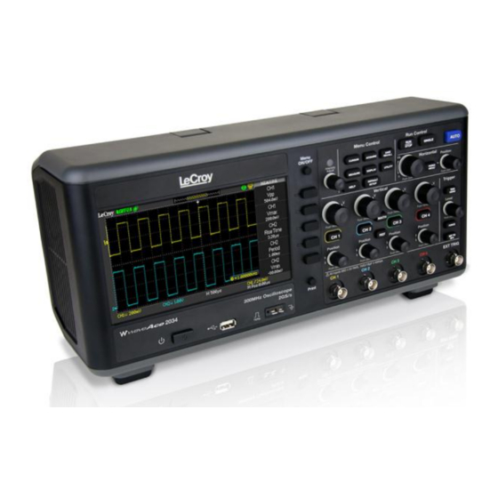
Operator's Manual Hardware Front Panel The WaveAce 1000/2000 Series oscilloscopes provide an easy-to-use front panel. The control buttons are logically grouped. Note : While the following picture is from the 4 Channel version, besides the extra channels, button and knob locations are essentially the same on the 2 Channel model. - Page 18 WaveAce 1000/2000 Back panel connection locations on the 4 Channel WaveAce Oscilloscope. Previously numbered front panel buttons and knob locations on 4 Channel models correspond with the following explanations. 1. Pass/Fail Output 2. RJ-45 Connector PLEASE NOTE THE FOLLOWING: Contact a system administrator when connecting to any internal LAN.
-
Page 19: Basic Controls
2000 models and top left on the 1000 models, when facing the instrument). 2. The LeCroy Splash screen is shown. Press any key to continue (or, after a brief period the grid display is shown). -
Page 20: Front Panel Controls
WaveAce 1000/2000 Note screen size varies slightly : The between all WaveAce Series Oscilloscopes. Therefore, the screen-shots in this documentation may look more narrow or wide than they appear on your specific model. However, the screens are all functionally the same and the slight differences have no affect when following these instructions. - Page 21 Operator's Manual setting the pulse width, setting the video lineage adjusting the upper and lower frequency limits, adjusting X and Y masks when using the Pass/Fail function, etc. You can also turn the Adjust knob to adjust the storage position of setups, waveforms, pictures when saving/recalling and to select menu options.
- Page 22 WaveAce 1000/2000 Menu Control Buttons CURSORS - Press to turn on the cursors and display the Cursor menu. You can use the Cursor menu to set the Cursor Mode (Auto, Off, Manual, Track). When Cursors are on (CURSORS button is lit), turn the Adjust knob to position the cursors. See Measuring with Cursors (on page 45) for more information.
- Page 23 Operator's Manual General Control Buttons Note : Exact Help, Default Setup, and AUTO button locations vary on 4 and 2 Channel models. HELP - Displays context-sensitive online help. Press Help, and then another front panel button and information pertaining to the selected button is shown.
- Page 24 WaveAce 1000/2000 Vertical Controls Volts/Div knobs (CH1-4, pictured) - Turn to adjust the volts/division setting (vertical gain) of the corresponding channel (CH1-4). Press the knob to toggle between fine (variable) and coarse (fixed) adjustments. See Vertical Settings and Channel Controls (on page 27) for more information.
- Page 25 Operator's Manual relative to the center of the screen). The resolution of this control varies depending on the timebase setting. Press to set the horizontal position to zero. HORI MENU - Press to display the Horizontal menu. You can use the Horizontal menu to display the waveform and to zoom a segment of a waveform.
- Page 26 WaveAce 1000/2000 SET TO 50% - Press to stabilize a waveform quickly. The oscilloscope can set the Trigger Level to be halfway between the minimum and maximum voltage levels automatically. This is useful when you connect a signal to the EXT TRIG connector and set the trigger source to Ext or Ext/5.
-
Page 27: Probes
Operator's Manual Probes Probes LeCroy provides a passive probe for each WaveAce oscilloscope channel. Probe Compensation Passive probes must be compensated to flatten overshoot. This is accomplished by means of a trimmer on the probe body. 1. Attach the connector end of your probe to any channel. -
Page 28: Viewing Waveforms
WaveAce 1000/2000 Viewing Waveforms Turning On Traces Turn on a channel trace by pressing the channel front panel button - CH1 or CH2 (or CH3 or 4 on 4 channel models). When you turn on a channel, the Channel menu opens. You can then set up the vertical settings and controls for the channel. -
Page 29: Understanding Display Information
Operator's Manual Display Menu Pages 1/3, 2/3, and 3/3 and their options are described as follows: 1. Type - Vectors fill the space between adjacent sample points in the display. Dots displays sample points directly. 2. Persist - Sets the length of time (1 sec, 2 sec, 5 sec, Infinite) each displayed sample point remains displayed. - Page 30 WaveAce 1000/2000 The previously numbered indicators correspond with the following explanations. 1. Trigger Status - The following four states are shown as highlighted text on this part of the screen. Armed - The oscilloscope is acquiring pre-trigger data. All triggers are ignored in this state.
- Page 31 Operator's Manual When a USB Memory Device is not inserted in the USB Port the area is blank. USB Memory Device is inserted in the USB Port (as shown previous). When plugging in or removing a USB Memory Device, a message is briefly shown on the grid display as USB Flash Drive Plug In! and USB Flash Drive Pull Out!, respectively.
-
Page 32: Auto Setup
WaveAce 1000/2000 14. Frequency Counter of Trigger Signal 15. Trigger type and level indicator 16. Horizontal Trigger Position Readout - Displays the waveform's horizontal position in time (seconds). Auto Setup The Auto Setup function identifies the waveform type and automatically adjusts controls to produce a usable input signal display. - Page 33 Operator's Manual Option Description Auto set the screen and display several cycle signal. (Multi-cycle) Set the screen and auto display single cycle signal. (Single-cycle) Auto set and show the rising time. (Rising edge) Auto set and show the falling time. (Falling edge)...
-
Page 34: Vertical Settings And Channel Controls
WaveAce 1000/2000 Vertical Settings and Channel Controls Vertical Settings and Channel Controls When you turn a channel trace ON, the Channel menu opens. The Channel menu page shown (1/3, 2/3, or 3/3) is always based on the most recent trace activated. Choosing Coupling You can choose one of these input coupling modes: ... -
Page 35: Limiting Bandwidth
Operator's Manual 1. Choose an input coupling mode. Turn on the desired channel by pressing the appropriate channel button - CH1 or CH2 (or CH3 or 4 on 4 channel models). 2. Now, press the Coupling option button on page 1/2 of the channel menu, and then select a coupling mode from the menu. -
Page 36: Adjusting Sensitivity
WaveAce 1000/2000 2. Now, press the BW Limit option button on page 1/2 of the channel menu, and then select On. Note : A highlighted icon is shown at the lower-left of the display as Understanding Display Information (on described in page 24 Adjusting Sensitivity You can set the sensitivity of the Volts/Div using the front panel knob. -
Page 37: Setting Probe Attenuation
Operator's Manual 2. Now, press the Volts/Div option button on page 1/3 of the channel menu, and then select Coarse (fixed) or Fine (variable). Setting Probe Attenuation Probes are available with various attenuation factors affecting the vertical scale of the signal. Push the Channel button, and then the Probe menu option button. -
Page 38: Inverting Waveforms
WaveAce 1000/2000 When the Attenuation switch is set to 1X, the probe limits the bandwidth of the oscilloscope to 10MHz. To use the full bandwidth of the oscilloscope, be sure to set the switch to 10X. Inverting Waveforms Use the following steps to invert your waveform. 1. -
Page 39: Unit And Skew Settings
Operator's Manual 3. Press the Filter option button on page 2/3. The Filter menu opens. 4. Press the Filter option button and select On. 5. Press the Type option button and select a digital filter type. 6. Press the Upp. Limit option button and turn the Adjust front panel knob to set the Upper limit. - Page 40 WaveAce 1000/2000 1. Pressing the Unit option button selects between V (Volts) and A (Amperes) values. 2. Pressing the Skew option button enables the Adjust front panel knob to set your desired value. WA1K2K-OM-E RevB...
-
Page 41: Acquisition Types
Operator's Manual Acquisition Types Acquisition Types When you acquire a signal, the oscilloscope converts it into a digital form and displays a waveform. The acquisition sampling mode defines how the signal is digitized and the timebase setting affects the time span and level of detail in the acquisition. - Page 42 WaveAce 1000/2000 2. If you select the Average sampling type, press the Averages option button and select the number of waveforms (4, 16, 32, 64, 128, or 256). Sinx/x Choose Sinx or x by pressing the corresponding option button. This turns Sinx/x on or off, respectively.
- Page 43 Operator's Manual Equivalent Time Sampling can achieve up to 20 ps of horizontal resolution (equivalent to 50 GS/s). This mode is good for observing repetitive waveforms. Real Time Sampling can be used for repetitive and non-repetitive waveforms. Select from the sampling settings by pressing the Mode option button and selecting Real Time or Equ Time.
-
Page 44: Zooming Waveforms
WaveAce 1000/2000 Acquiring Waveforms You can choose to acquire a single waveform or to acquire waveforms continuously. If you want to acquire a single waveform, press the SINGLE front panel button. Each time you press the SINGLE front panel button, the oscilloscope begins to acquire another waveform. - Page 45 Operator's Manual 1. Press the HORI MENU front panel button. The Horizon menu is shown. 2. Press the Delayed option button on the Horizontal menu (or pressing the Time/Div Front Panel (on page 10) knob). 3. Turn the Time/Div front panel knob to adjust the Zoom segment window size.
-
Page 46: Triggering
WaveAce 1000/2000 Triggering Trigger Types There are five trigger types: Edge, Video, Pulse, Slope, and Alternative. Access the trigger modes by pressing the TRIG MENU front panel button (in the Trigger control group) and selecting Type from the Trigger menu. Edge Triggering 1. -
Page 47: Pulse Triggering
Operator's Manual Pulse Triggering Use Pulse width triggering to trigger on aberrant pulses. You can select how to compare the trigger pulse relative to the pulse width as follows: Positive pulse width less than pulse width setting Positive pulse width larger than pulse width setting ... -
Page 48: Video Triggering
WaveAce 1000/2000 trigger). Use Single mode when you want the oscilloscope to acquire a single waveform. 7. Press the Setup... option button to display the Trigger Setup... menu. You can use the Trigger Setup... menu to select a coupling mode and define a Holdoff value. Coupling modes comprise DC, AC, HF Reject, and LF Reject. -
Page 49: Slope Triggering
Operator's Manual the absence of a trigger. Use Normal mode when you want to see only valid triggered waveforms (when you use this mode the oscilloscope does not display a waveform until after the first trigger). Use Single mode when you want the oscilloscope to acquire a single waveform. -
Page 50: Alternative Triggering
WaveAce 1000/2000 7. Press the Mode option button to select Auto, Normal, or Single mode. Use Auto mode to let the acquisition automatically run in the absence of a trigger. Use Normal mode when you want to see only valid triggered waveforms (when you use this mode the oscilloscope does not display a waveform until after the first trigger). - Page 51 Operator's Manual 4. For the selected trigger type, set the trigger options. 5. Press the Setup... option button to display the Trigger Setup... menu. You can use the Trigger Setup... menu to select a coupling mode and define a Holdoff value. Coupling modes comprise DC, AC, HF Reject, and LF Reject.
-
Page 52: Analyzing Waveforms
WaveAce 1000/2000 Analyzing Waveforms Analyzing Waveforms Four main front panel buttons are used for waveform analysis. Two Menu Function front panel buttons - Cursors, Measure The other two are Vertical front panel buttons - Math, REF The following topics explain their detailed use. Measuring with Cursors Cursors are important tools that aid you in measuring signal values. - Page 53 Operator's Manual Voltage cursors appear as horizontal lines on the display and measure the vertical parameters. Time cursors appear as vertical lines on the display and measure the horizontal parameters. Move cursors by pressing corresponding CurA, CurB option buttons, and then using the Adjust front panel knob. Before using cursors, you should make sure that you have set the signal source as the channel for measuring.
-
Page 54: Cursor Measurement Selections
WaveAce 1000/2000 You can adjust the cursor position on the waveform by turning the Adjust front panel knob. Measurement values are shown in the upper-left corner of the grid display. 3. Auto - Automatically places markers of what is being measured on the waveform. - Page 55 Operator's Manual A→T - the horizontal position of Cursor A (Time cursor centered around the midpoint of the screen) A→V - the vertical position of Cursor A (Voltage cursor centered on the channel ground level) B→T - the horizontal position of Cursor B (Time cursor centered on the midpoint of the screen) B→V - the vertical position of Cursor B (Voltage cursor centered around the channel ground level)
-
Page 56: Parameter Measurements
WaveAce 1000/2000 Voltage (horizontal cursors) or Time (vertical cursors). Press the Source option button and select a source of CH1, CH2 (also, CH3 and 4 on 4 channel models). Manual Mode also allows you to choose MATH, REFA, or REFB as a Cursor source. Press the CurA or CurB option button and turn the Adjust front panel knob to adjust the cursors. - Page 57 Operator's Manual Measure menu is labeled with a CHX, a Type, and a Value. Each row is a customizable parameter measurement preset. Press the corresponding option button to show additional preset controls for Voltage, Time, Delay, and AllMea for the Source channel selected. WA1K2K-OM-E RevB...
- Page 58 WaveAce 1000/2000 Voltage Measurement Parameters First select a Source Channel for your Voltage measurement parameter by pressing the Source option button. Now, use the Type option button to choose from the following Voltage measurement parameters for your selected source. Vpp - Difference between highest and lowest points in the waveform.
- Page 59 Operator's Manual Vbase - Lower of two most probable states (higher is top). Measures lower level in two-level signals. Differs from min in that noise, overshoot, undershoot, and ringing do not affect measurement. Vavg - Arithmetic mean over the first cycle in the waveform.
- Page 60 WaveAce 1000/2000 after left cursor, period is measured for each transition pair, with values averaged to give final result. +Wid - Time between the first rising edge and the next rising edge at the waveform 50% level. -Wid - Time between the first falling edge and the next rising edge at the waveform 50% level.
- Page 61 Operator's Manual Phase - Amount one waveform leads or lags another in time expressed in degrees, where 360 degrees comprise one waveform cycle. FRR - Time between the first rising edge of Source 1 and the first rising edge of Source 2. ...
-
Page 62: Waveform Math
WaveAce 1000/2000 Press corresponding option buttons and make selections as desired. Waveform Math Standard math functions include addition, subtraction, multiplication, division, and FFT. For more information on FFT, see the FFT Spectrum Analyzer (on page 57) section. Press the MATH front panel button in the Vertical Control group to display the Math menu. - Page 63 Operator's Manual 2. The Source can be any channel, but not another math trace. Channel behavior for the math operators allow for CH1-CH2 or CH2-CH1 selections. Math on 4 Channel WaveAce Models Math Menu Pages 1/2 and 2/2 and their options are described as follows: 1.
-
Page 64: Fft Spectrum Analyzer
WaveAce 1000/2000 4. Adjust the scale of your math trace by pressing the following option button and turning the Adjust knob as desired. FFT Spectrum Analyzer The FFT process mathematically converts a time-domain signal into its frequency components. You can display only one FFT waveform at a time. - Page 65 Operator's Manual Window Description Test Content Type Rectangular Best frequency resolution, Symmetric transients or worst magnitude bursts. Equal-amplitude sine resolution. This is waves with fixed frequencies. essentially the same as no Broadband random noise with window. a relatively slowly varying spectrum.
-
Page 66: Creating Reference Waveforms
WaveAce 1000/2000 Note Split Display : The previous screen-shot shows a math trace in view. 4. The Display option button allows you to choose either Split or Full Screen for your FFT trace display. Note Full Screen : The previous screen-shot shows a math trace in Display view. - Page 67 Operator's Manual 2. Press the Source option button to select the input signal channel. 3. Use the lower REF A option button to turn the reference waveform On or Off. This also shows or hides the reference waveform from the grid display area.
- Page 68 WaveAce 1000/2000 5. Use the Save option button to save your reference waveform for comparative analysis at a later time. Note : Keep in mind that the reference waveforms are stored in volatile memory. This means that REF A and REF B are temporarily stored until the next time the oscilloscope is shut down.
-
Page 69: Save And Recall
Operator's Manual Save and Recall Saving and Recalling Oscilloscope Settings You can quickly save and recall up to 20 oscilloscope panel settings and 20 waveforms in internal memory. Waveforms and panel settings can also be saved to a USB memory device. Saving the Current Settings 1. - Page 70 WaveAce 1000/2000 Insert the USB memory device, press the Save To option button and select File. Press the Save option button and the SAVE ALL screen opens showing Directorys by default. Finish saving your setup using the following instructions in Using the SAVE ALL Screen (on page 74).
-
Page 71: Saving And Recalling Waveforms
Operator's Manual shows a Read Data Success! message on the lower part of the grid display area. Recalling Setups from a USB Memory Device Insert the USB memory device and press the Save To option button to select File. ... - Page 72 WaveAce 1000/2000 Press the Waveform option button or turn the Adjust knob to assign a number (No. 1 - No. 20) to the waveform. Press the Save option button to save the waveform. The waveform is saved to memory and the oscilloscope briefly shows a Store Data Success! message on the lower part of the grid display area.
-
Page 73: Saving And Printing Waveform Pictures
Operator's Manual 3. Recall the waveform either from your Device (meaning internal memory on your WaveAce) or from a File (stored on a USB memory device) using the following methods. Recalling Waveforms from Internal Memory Press the Save To option button to select Device. ... - Page 74 WaveAce 1000/2000 3. Print or Save your .BMP pictures to a USB memory device using the following methods. Printing Directly to a Printer Press the Print Key option button and select Print Picture. Be sure a printer is connected to your WaveAce oscilloscope.
-
Page 75: Saving Data As A .Csv File
Operator's Manual With either Save or Print Picture chosen from the Print Key option button (and corresponding options setup as explained in Print Setup (on page 88)), simply press the Print front panel button to instantly execute your selected function. ... - Page 76 WaveAce 1000/2000 2. Press the Type option button and select CSV. 3. Press the Data Depth option button and select Maximum or Displayed. These values correspond to all waveform data for the channel or just the exact waveform data shown within the grid display, respectively.
-
Page 77: Recalling Factory Settings
Operator's Manual PLEASE NOTE THE FOLLOWING: The Recall option is excluded from Save/Recall menus when Picture or CSV is selected as the Type. The Load option is disabled (grayed-out) on menus inside the SAVE ALL screen when Pictures or CSV file types are selected as Type. - Page 78 WaveAce 1000/2000 The default settings made to the oscilloscope are detailed as follows: Menu Option Default Coupling CH1,CH2 BW Limit (2 Channel Models) Volts/div adjust Coarse (fixed) CH1,CH2, CH3, CH4 (4 Channel Models) Probe Invert Volts/div 1.00V Menu Option Default MATH Operation (2 Channel Models) CH1-CH2...
- Page 79 Operator's Manual Menu Option Default Sec/div 500μs Window Zone 50.0μs Trigger Knob level Menu Option Default CURSOR Type Source Horizontal (voltage) ±3.2divs Vertical (time) ±5divs Menu Option Default MEASURE Source Type average Menu Option Default ACQUIRE Mode Sampling Averages Menu Option Default DISPLAY...
- Page 80 WaveAce 1000/2000 Menu Option Default Type Waveform Source Menu Option Default TRIGGER (Edge) Type Edge Source Slope Rising Mode Auto Coupling Level 0.00V Menu Option Default TRIGGER (Pulse) Type Pulse Source When Set Pulse Width 1.00ms Mode Auto Coupling Menu Option Default TRIGGER (Video)
-
Page 81: Using The Save All Screen
Operator's Manual Menu Option Default Standard NTSC Menu Option Default TRIGGER (Slope) Type Slope Source Mode Auto Menu Option Default TRIGGER (Slope) Type Alternative Source Using the SAVE ALL Screen The SAVE ALL screen is divided into functions (New, Delete, Load, and Rename) based on modifying a Directory or Files when saving items to a USB memory device. - Page 82 WaveAce 1000/2000 WA1K2K-OM-E RevB...
- Page 83 Operator's Manual The SAVE ALL - Files Menu While Files shows option buttons for New File, Delete File, and Load. Note File Setups Waveforms Pictures : Use these functions to save , and Data Recalling Files The Load button is used to recall your setup files. Once you've navigated to the desired file and it's highlighted in the main screen area, press the Load option button and the setup is recalled from the USB memory device.
- Page 84 WaveAce 1000/2000 PLEASE NOTE THE FOLLOWING: As shown in the previous screen-shot, the system warns you if you try to load an incorrectly formatted file. The Load option is disabled (grayed-out) when Pictures or CSV file types are selected as Type. The SAVE ALL Menu - Page 2/2 Both Directories and Files have Rename and Return option buttons on Page 2/2.
- Page 85 Operator's Manual The New File menu choices and behavior is the same as the New Folder menu. It just has a different heading. The InputChar option button adds the selected character to the cursor position in the Name field. ...
-
Page 86: Utilities
WaveAce 1000/2000 Utilities Utility Menu You can use the Utility menu to configure your oscilloscope. Press the UTILITY Front Panel (on page 10) button to display the Utility menu. The first of four available pages containing various utility functions is shown. The screens and functions are covered in the following sections. - Page 87 Operator's Manual 2. Press the Sound option button to turn tones On/Off as desired. 3. Turning the Frequency Counter On/Off shows or hides it from the grid display. 4. Press the Language option button to choose the local language of the user interface.
- Page 88 WaveAce 1000/2000 Utility Menu - Page 2/4 1. Press the Do Self Cal option button to perform a self-calibration. The Do Self Cal screen is shown. 2. As the screen indicates, disconnect anything plugged into input connectors (except for the power cable) before pressing the SINGLE Front Panel (on page 10) button and performing a self- calibration.
- Page 89 Operator's Manual Note : The system indicates which channel is being calibrated above the progress bar. 4. Press the SINGLE front panel button when self-calibration is complete. 1. Press the Do Self Test option button to perform a self-test. A separate SELF TEST screen is then shown.
- Page 90 WaveAce 1000/2000 Note Do Self Cal : After using corresponding option buttons to choose Do Self Test Print Setup , or (when enabled by selecting Printer on the Back USB option button), you're taken to a separate menu based on your selection where additional options are then shown. You can always return to the original menu from this menu by pressing the UTILITY front panel button.
- Page 91 Operator's Manual Screen Test - Each press of the SINGLE front panel button runs successively through colors and is how the Screen Test is performed. Move through a few colors until you are satisfied. As the screen indicates, press the RUN/STOP front panel button to exit. Keyboard Test - As front panel buttons and knobs are pressed and turned, the screen colorizes their corresponding location on the test screen, indicating correct function and a successful test.
- Page 92 WaveAce 1000/2000 RINT ETUP 1. Press the Print Setup... option button to set up your print options. A separate Print screen is then shown (Page 1/2). PLEASE NOTE THE FOLLOWING: Only when the Back USB option button (covered in the next step) is set to Printer is the Print Setup...
- Page 93 Operator's Manual Utility Menu - Page 3/4 1. Press the Update Firmware option button to update the oscilloscope using the USB memory device. For more information, see the Updating the System Software (on page 90) section. 2. Pressing the Pass/Fail option button shows the Pass/Fail menu where you can monitor changes of signals and output pass or fail signals by judging whether the input signal is within the predefined mask.
- Page 94 WaveAce 1000/2000 Use the top/first Menu Option button to move through IP Address, Subnet Mask, Gate Way, and DHCP controls. Push the Adjust Front Panel (on page 10) knob to move within a control and turn the knob to change values. Note Save/Recall Front Panel (on : As indicated, press the...
-
Page 95: Print Setup
Operator's Manual screen saver mode. Time length options include 1min , 2min, 5min, 10min, 15min, 30min, 1hour, 2hour, 5hour and Off. Of course, selecting Off keeps the oscilloscope from entering screen saver mode entirely. 2. Pressing the Date/Time option button shows the Date/Time menu where you can make this setting and choose to show it on the lower-right of your display. - Page 96 WaveAce 1000/2000 Ink Saver - Turn this option button control On or Off to help save ink on your printer (if you have one) connected to the back of your instrument. Layout - Choose from Portrait or Landscape print layouts as desired.
-
Page 97: Updating The System Software
LeCroy periodically releases software updates for the WaveAce providing new features, enhancements, and software corrections. These updates are available for download from the LeCroy website at www.lecroy.com. After registering your product, you can select the appropriate download based on your specific WaveAce oscilloscope model. - Page 98 WaveAce 1000/2000 After downloading, open the .zip file on your computer. The .zip should contain an .ads file and the Firmware Update Procedure .pdf file. Move the .ads file to a USB memory device. The system software update .ads file is then loaded through the USB memory port on the front of the oscilloscope.
- Page 99 Operator's Manual Press the SINGLE front panel button to begin loading the .ads firmware update file from your USB memory device Using the SAVE ALL Screen (on page 74). Otherwise, press the RUN/STOP front panel button to exit the Update Firmware screen. ...
-
Page 100: Using Pass/Fail
WaveAce 1000/2000 Using Pass/Fail The Pass/Fail function monitors signal changes determining whether or not it falls within a predefined mask. Access Pass/Fail by pressing the corresponding option button on the Utility menu. The first of two Pass/Fail menus is then shown. Pass/Fail - Page 1/2 After pressing the Pass/Fail option button, the first of two Pass/Fail menus (Page 1/2) is shown and contains the following option button... - Page 101 Operator's Manual Note Enable Test On/Off : Turning allows you to control whether or not the mask is shown on the display grid area while making your Operate settings. The button runs the test and allows you to see the results update in real time.
- Page 102 WaveAce 1000/2000 X Mask - Press the X Mask option button and use the Adjust Front Panel (on page 10) knob to dial in the desired range of horizontal waveform clearance (0.04div - 4.00div). Y Mask - Press the Y Mask option button and use the Adjust front panel knob to dial in the desired range of vertical waveform clearance (0.04div - 4.00div).
-
Page 103: Using Record
Operator's Manual Save - Press the Save option button to store your mask. After pressing, the mask is saved Internally, or the SAVE ALL screen is shown, depending on your Location control setting (choose Internal or External as desired on Mask - Page 1/2). - Page 104 WaveAce 1000/2000 The Record function operates in three Modes: Off, Record, and Playback. As shown previous, no option button controls are available when the Record's Mode is set to Off. The Record Menu (with Mode Set to Record) Press the Mode option button and select Record. The Record menu (with Mode set to Record) is shown and contains the following option button controls (in addition to Mode).
- Page 105 Operator's Manual 2. Press the Interval option button and use the Adjust Front Panel (on page 10) knob to dial in the desired interval between record frames. 3. Press the End Frame option button and use the Adjust front panel knob to dial in the desired number of record frames.
- Page 106 WaveAce 1000/2000 2. Press the Play Mode option button to choose from Circular (repeat) or Single time (play once, and then stop) modes. 3. Press the Interval option button and use the Adjust front panel knob to dial in the desired interval between record frames for the playback of your recorded waveforms.
-
Page 107: Setting And Displaying The Date/Time
Operator's Manual 3. Press the End Frame option button and use the Adjust front panel knob to dial in the specific frame of your recorded waveforms where you want to end the playback. 4. Press the Return option button or the Utility Front Panel (on page 10) button and the Utility menu is shown. - Page 108 WaveAce 1000/2000 WA1K2K-OM-E RevB...
-
Page 109: Reference
Operator's Manual Reference Using WaveStudio to Remotely Connect to your WaveAce Oscilloscope The following steps demonstrate how to use WaveStudio to remotely connect to your WaveAce oscilloscope. 1. Make the hardware connection to your oscilloscope. Connect a network cable to the RJ-45 connector on the back of your oscilloscope as shown in Back and Side Connections (on page 10). - Page 110 Now, it's time to launch WaveStudio on your computer. Note : The WaveStudio installation is always available at www.lecroy.com/sw/wavestudio. With the software launched, select Add Scope by clicking the button for this action, which can be found in The Scope Ribbon, or using its miniature form on the top portion of the My Scope (Device) Explorer.
- Page 111 Operator's Manual Click either the Network (for WaveAce 2000 models with an RJ-45 connector on the Back Panel) or USBTMC/USB488 (for either 1000/2000 models using the USB Type B connector) device connection button. See Back and Side Connections (on page 10) for more information. After selecting your device connection, WaveStudio completes the setup and the added device configuration is shown on The Scope (Device) Explorer window.
-
Page 112: Waveace Specifications
: Specifications are subject to change without notice. Please refer to the LeCroy website at www.lecroy.com or the online help on your LeCroy oscilloscope for detailed specification information. CERTIFICATIONS CE Compliant, UL, and cUL Listed CE Declaration of Conformity The oscilloscope meets requirements of EMC Directive 2004/108/EEC for Electromagnetic Compatibility and Low Voltage Directive 2006/95/EEC for Product Safety. - Page 113 Operator's Manual (3 V/m, 80-1000 MHz; 3 V/m, 1400 MHz - 2 GHz; 1 V/m, 2 GHz - 2.7 GHz) EN 61000-4-4:2004** Electrical Fast Transient/Burst. (1 kV on power supply lines, 0.5 kV on I/O signal data and control lines) ...
-
Page 114: Ul And Cul
WaveAce 1000/2000 Installation Categories II (Mains Supply Connector) and I (Measuring Terminals). Pollution Degree 2 (Normally only dry non-conductive pollution occurs. Occasionally a temporary conductivity caused by condensation must be expected.) Protection Class I (Provided with terminal for protective ground). UL and cUL The oscilloscope is UL and cUL listed and conforms to the following standards:... - Page 115 Operator's Manual Toxic or Hazardous Substances and Elements Lead Mercury Cadmium Hexavalent Polybrominated Polybrominated Part Name (Pb) (Hg) (Cd) Chromium Biphenyls Diphenyl Ethers (Cr6+) (PBB) (PBDE) PCBAs Mechanical Hardware Sheet Metal Plastic Parts Cable Assemblies Display Power Supply Fans Battery for Processor Power Cord Ext Power...
-
Page 116: Contact Lecroy For Support
Whether you're looking for sales or technical support, our staff can provide assistance with installation, calibration, and product knowledge regarding a full-range of our software applications and accessories. You can also find contact information for our offices on the LeCroy Web sites shown for the following regions: WA1K2K-OM-E RevB... - Page 117 Operator's Manual Contact Your Local LeCroy Office for Sales and Technical Assistance United States and Canada - World Wide Corporate Office LeCroy Corporation 700 Chestnut Ridge Road Chestnut Ridge, NY, 10977-6499 Phone (Sales, Applications, and Service): 800-553-2769 (options 1, 2, and 3,...
- Page 118 WaveAce 1000/2000 Contact Your Local LeCroy Office for Sales and Technical Assistance Korea - Seoul China LeCroy Korea LeCroy Corporation Beijing Office and Service Center 10th fl.Ildong Bldg. Rm. 2001 - Office; Rm. 2002 - Service 968-5 Daechi-dong, Gangnam-gu Center...
- Page 119 Operator's Manual Contact Your Local LeCroy Office for Sales and Technical Assistance Taiwan Tokyo LeColn Technology Co Ltd LeCroy Japan Far East Century Park, C3, 9F, Hobunsya Funchu Bldg, 3F No. 2, Chien-8th Road, 3-11-5, Midori-cho, Fuchu-Shi Chung-Ho City, Tokyo, 183-0006...
-
Page 120: Index
WaveAce 1000/2000 Index Date/Time, 91 abnormal conditions, 13 Delay, 57 ac power source, 10 Do, 84, 85 Acquiring, 41 Acquisition Types, 38 Adjusting, 33 All Mea (Measurement) Settings, 58 Edge, 43 Alternative, 47 Analyzing Waveforms, 49 Auto, 29, 51 FFT Spectrum Analyzer, 61 Average, 38 Front, 14, 17 Back, 14, 88... - Page 121 Operator's Manual Language, 83 Quick, 91 Limiting, 32 Recalling, 67, 69 Manual, 49 Run, 20 Mask, 97, 98 Measuring, 49 Menu Control Buttons, 19 Safety, 8 Menu Control, Option and Print Safety Requirements, 6 Buttons, 18 safety symbols, 6 Mode Selection, 39 Sampling, 38, 40 Saving, 66, 68, 70, 72 Saving and Recalling Oscilloscope...
- Page 122 WaveAce 1000/2000 Time, 56 Utility Menu - Page 3/4, 89 Track, 50 Utility Menu - Page 4/4, 90 Trigger, 23, 43 Turning, 25 Type, 66 Vertical, 21 Vertical Settings and Channel Controls, 31 Video, 45 Understanding, 26 Voltage, 55 Unit and Skew Settings, 36 Update, 89 Updating, 93 USB Speed, 91...
- Page 123 Operator's Manual WA1K2K-OM-E RevB...
Need help?
Do you have a question about the WaveAce 1000 series and is the answer not in the manual?
Questions and answers