Table of Contents
Advertisement
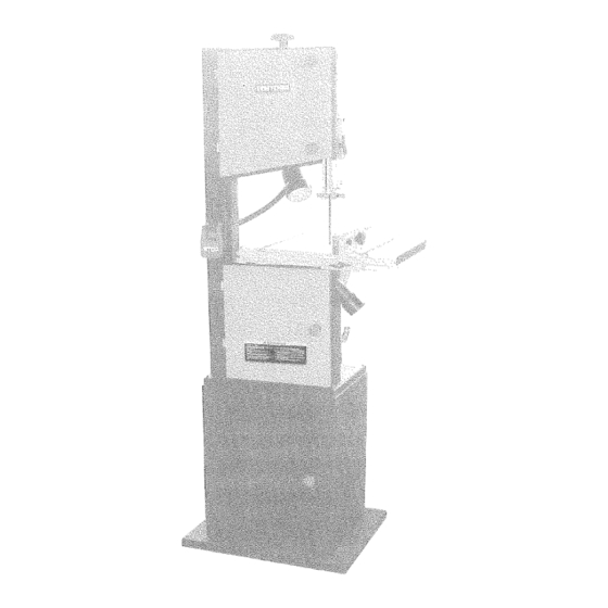
Owner's
Ma_uat
14=in.
I HP bIOTOR
Model
119.2240 _0
CAUTIONh
Before using this
product, read thismanual and
follow
all its Safety
Rules
and Operating
Instructions.
¢ Table of Contents
÷ FullOne Year Warranty
e Safety Instructions
e Assembly
÷ Getting to Know
Your Bandsaw
÷ Adjustment
e Operation
e Maintenance
e Electrical
Schematic
÷ Troubleshooting
e Parts List
Soars,
Roebuck
and Co., Hoffman Estates,
IL 60179, U.S.A.
www.crafteman.com
OM-224OZ-MZ
Advertisement
Table of Contents

Related Manuals for Craftsman Professional 119.224010


Summary of Contents for Craftsman Professional 119.224010
- Page 1 Owner's Ma_uat 14=in. I HP bIOTOR 119.2240 _0 Model ¢ Table of Contents CAUTIONh Before using this ÷ FullOne Year Warranty product, read thismanual and e Safety Instructions follow all its Safety Rules e Assembly and Operating Instructions. ÷ Getting to Know Your Bandsaw ÷...
- Page 2 Troubleshooting ........................................Parts list ..........................................If this Craftsman tool fails due to a defect in material or workmanship within one year from the date of purchase, CALL 1-8O0-4-MY-HOME® TO ARRANGE FOR FREE REPAIR. This warranty applies only while this tool is in the United States.
- Page 3 Always Wear Proper Apparel. Never weal loose clothing or jewelry that might get caught in moving pails. Rubber-soled footwear recommended for the best footing. Always Use safety G_asses and Wear Hearing Protection, Also use a face or dust mask if the cutting operation is dusty. Never Overreach.
- Page 4 1. TOOLS REQUIRED FOR ASSE[_BLY LIST, OF LOOSE PARTS IN BAG Item Description Item Description 2-1t2" Dust port ..............Ph I psScrewdriver ........ Hex. Socket head cap screw M6x12 ....2 Adjustable Wrench ......... Washer 6............Square ............Blade tension knob .......... Crank handle ...........
- Page 5 3. INITIAL ASSEMBLY The machine is supplied partly assembled. Prior to use, the following items have to be installed: Cabinet stand, 2-1/2" dust port, Table, Rip Fence, Blade Tension Knob, Tool holder, and Crank handle, WARNING: To avoid injury, do not attempt to run or use this machine until all parts are assembled and working properly. a.
- Page 6 h.Thebandsaw hasa2-1/2" dust p ort a nd4"dust p ort i ncluded. e.Toassemble theripfence, take thefence carrier(A) andattach i t (See Fig.8) totheguide rail(B) u sing t heM8x50 c arriage bolt(C) andthewing Itis recommended thatwhen inuse, i hebandsaw i sconnected to nut(D).
- Page 7 Blade tension knob locking knob 3lade trackinc Guide post LamP uide Switch / rail Upper table Fence _/ /2" Dust port Lower table 4" Dust 1o C_NTERi_,aC¢ _'lqE TABLE a. I.oosen the [our hey, bolts mounting the table to the upper table h'Linnion.
- Page 8 3. SETTING TABLE SQUARE FRONT AND BACK b. Horizontal alignment of the rip fence is made by adjusting the two knurled nuts and the fence adjusting knob. BLADE The fence should be aligned with the table slots along its length.(See FIG. 17) Place a suitably sized square against the saw blade on back and force position.
- Page 9 WARNING: Toavoid injury f rom unexpected starting, whenever 10. SETTING THE CUTTING HEIGHT changing thesawblade orcarrying outadjustments; switch t he bandsaw offandremove thepower cord from themain outlet. To a. The upper blade guide should be set as close as practical avoid injury tohands w hen handling thesawblade, wear gloves against the workpiece.
- Page 10 The Lower Blade Guide For the high speed 3340 Pd'min,the belt should be fitted to the rear a. To adjust the lower blade guides, first position the right and left pulley on both the motor and bandwheel. (See FIG.26) roller guides relative to the blade by loosening the lock nut F{G.24 and moving the guide carrier until both roller guides are approxi- mately 1116"...
- Page 11 For best results the saw blade must be sharp. Select the right saw WARNING: Before starting check if any par[ of your bandsaw is blade for [he job, depending on the thickness at the wood the cut to missing, malfuctioning, has been damaged or broken.., such as be made.
- Page 12 Preblem Diagnosis Remedy 1. Check the cable for breakage. The machine does not work when 1. No power supply, 2. Defective switch. 2, Replace the lock switch, switched on. 3 Defective motor. 3. Defective motor. I. Switch off the motor, tighten the blade !.
- Page 13 _ "i ¸ _...
- Page 14 DESCRIPTION DESCRIPTION KEYNO. KEY NO. DESCRIPTION KEYNO. Carriage bolt M6x40 Carriage bolt M8xl00 Door locking knob Cap Washer 6 Motor Hex. Bolt M6x40 Knurled nut M6 Motor cable Door locking knob body Hex, Nut M6 Hex. Bolt M6x20 Hex. Nut M6 Hex.
- Page 15 Your Home For repair-in you_ home=of at! major brand appliances, tawn and garden equipmen% or heating and cooling systems, no matte_ ° who made it_ no _at1:er who so_d if;! ¸!! For the replacement parts, accessorbs owneds manuals that you need to doqt=yourself. For Sears professional installation of home appliances and items like garage door openers and water heaters°...