Table of Contents
Advertisement
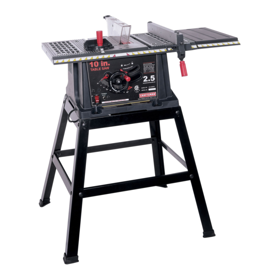
Operator's
Manuam
m
CAUTION:
Before using this Table Saw,
read this manual and follow
all its Safety Rules and
Operating
Instructions
o
Safety Instructions
o
Installation
o
Operation
+
Maintenance
o
Parts List
Customer
Help
Line
1 o800o843ol
682
Sears, Roebuck
and Co., Hoffman
Estates,
IL 60179 USA
Visit
our Oraftsman
website:
www.sears.com/craftsman
Part No. 137218010001
Advertisement
Table of Contents

Related Manuals for Craftsman 137.218010


Summary of Contents for Craftsman 137.218010
- Page 1 Before using this Table Saw, read this manual and follow Operation Maintenance all its Safety Rules and Parts List Operating Instructions Customer Help Line 1 o800o843ol Sears, Roebuck and Co., Hoffman Estates, IL 60179 USA Visit our Oraftsman website: www.sears.com/craftsman Part No. 137218010001...
-
Page 2: One Year Full Warranty
SECTION PAGE SECTION PAGE Warranty ............Assembly and Adjustments ......Product Specifications ........Operation ............Maintenance ............ Power Tool Safety ........... Tabe! Saw Safety ..........Troubleshooting Guide ........Push Stick Pattern ........... Electrical Reuirements and Safety ....Carton Content ..........Parts List ............ - Page 3 IAWARNING Before using your table saw, it is critical that you read and understand these safety rules. Failure to follow these rules could result in serious injury or damage to the table saw. Good safety practices are a combination of common l&...
- Page 4 14. AVOID AWKWARD OPERATIONS and hand ALWAYS USESAWBLADEGUARD, splitter a nd anti-kickback pawls foreveryoperation f orwhich positions where a sudden slip could cause your hand to move into the saw blade. theycanbeused, i ncluding through-sawing. Through-sawing operations a rethoseinwhich the 15_ NEVER USE SOLVENTS to clean plastic parts.
-
Page 5: Power Supply Requirements
POWER SUPPLY REQUIREMENTS GROUNDING INSTRUCT_ONS IN THE EVENT OF A MALFUNCTION IAWARNING BREAKDOWN, grounding provides a path of least resistance for electric current and reduces the risk of To avoid electrica! hazards, fire hazards or damage to the chop saw, use proper circuit protection. Always use electric shock. -
Page 6: Recommended Accessories
Loose Parts" to make certain all items are accounted for, before discarding any packing material Visit your Sears Hardware Department or see the Craftsman Power and Hand Tools Catalog to purchase [A WARNING ] recommended accessories for this power tool. - Page 7 UNPACKING YOUR TABLE ® ° 7...
- Page 8 Blade guard Table insert Rip fence Miter gauge Side table extension Bevel angle pointer & scale Blade bevel Lock knob Overload reset switch Blade elevation & tilting hanwheel ON/OFF switch with safety key Front stand Stand mounting holes Anti-kickback pawls Blade Splitter Splitter bracket...
- Page 9 ASSEMBLE TABLESAWTOSTAND (FIG.A-I) ASSEMBLE STAND (FIG. A } 1. Placeprotective c ardboard o r oldblanket onfloorto 1. Unpack allparts andgroupbytypeandsize.Refer protect t hesawtablesurface. tothepartslistforcorrect q uantities. 2. Place thesawupsidedown ontheprotective 2. Attach onelonguppersupport ( 4)totopofleg(1) material (seeFig.A-I). usingonebolt(2)andnut(5). 3. Position thestandupsidedownonthesawbase. NOTE: D onottightenboltsuntil s tandis properly NOTE: M akesurefrontofstandandfrontofsaware aligned (seestep#8before tightening).
-
Page 10: Keeping The Area Clean
SAWMOUNTED T OWORKSURFACE (FIG.B) ASSEMBLE BLADE RAISING & TILTING WHEEL 1. If the leg set will not be used, the saw mustbe (FIG. C} properlysecuredto a sturdyworkbench usingthe 1. Attach blade raising & tilting hand wheel (1) to the fourmounting holes at thebaseofthesaw. height regulating bolt (2). - Page 11 2. Liftupward on ripfencehandle (2)sothe rearholding Fig. F clamp(4)isfullyextended. 3. Placethe rip fenceon the sawtable(5),engaging the rearfenceclampfirstthenlowering thefrontend ontothetable. 4. Push downonthefencehandle (2)tolock. Fig.E INSTALLING AND CHANGING THE BLADE (FIG. H, t, J) DANGER] o To avoid injury from an accidental start, make sure the switch is in the OFF position and the plug is not connected to the power source outlet.
-
Page 12: Blade Guard Assembly
5_ Instal!the sawbladeontothe arborwiththe blade BLADE GUARD ASSEMBLY (FIG. K, L, M) teethpointing toward thefrontofthesaw. 1. Set the blade to maximum height and the tilt to zero 6_ Install t heflange (6)against t he bladeandthreadthe degrees on the bevel scale with the hand wheels. arbornut(5)as faras possible by hand.Ensure that Lock the blade bevel lock knob. -
Page 13: Miter Gauge Adjustment
4+ Jf adjustment is needed to make the fence parallel to the groove, proceed with the following adjustments: ® Loosen the two bolts (3) and lift up on the handle (2)+ + Hold the fence bracket (4) firmly against the front of the saw table+ Move the far end of the fence until it is parallel with the m+tergauge groove. - Page 14 BLADETtLTJNG MECHANISM BLADE PARALLEL TO THE MITER GAUGE Thesawbladecanbetiltedtwodifferent w ays. GROOVE (FIG. Q, R) This adjustment was made at the factory, but it should RAPID BLADETtLTING (FIG.P) be rechecked and adjusted if necessary. 1. Loosen bladebevel l ockknob(2). WARNING 2.
-
Page 15: Adjustment Procedure
ADDiTiONAL B LADEADJUSTMENTS (FIG.R) 7. Tighten both middle blade alignment rod strap bolts TOOLS REQUIRED (1). NOTE: Re-check to make sure all six bolts are properly tightened and that the distance from the o 10mm openendor 10ram combination w rench front and rear of the blade to the miter gauge groove ®... -
Page 16: Bevel Stop
BEVEL POINTER ADJUSTMENT (FIG. T ) Whenyouhaveachieved a 90° angleofthebladeto thetabletopas described i nsection above, t heangle pointer m ayrequire adjustment. If so,followproceeding steps: 1. Loosen pointer screw(2) andmovethe pointer so it is aligned with0° onthebevel s cale. 2. Retighten t hepointer s crew. 45°... - Page 17 8ASmC SAW OPERATmONS across the width or across the grain of the workpiece. Neither ripping nor crosscutting may be done safely ON/OFF SWITCH (FIG. V) freehan& Ripping requires the use of the rip fence, and The on/off switch (2) is located on the front panel of the crosscutting requires the miter gauge.
- Page 18 IAWARNING RIPPING SMALL PIECES [_ WARNING AVOID KICKBACK by pushing forward that section of the workpiece that wil! pass between the blade and the Avoid injury from the blade contact. Never make fence. Use a push stick at all times. through-saw cuts narrower than 3/4 in.
- Page 19 Fig,Y COMPOUND MITER CROSSCUTTING (FIG. BB} 00~45 ° BLADE BEVEL & 00~45° rvIITER ANGLE This sawing operation is combining a miter angle with a bevelangle_ WARNING Always work to the right side of the blade during this type of cut. The miter gauge must be in the right side groove because the bevel angle may cause the blade guard to interfere with the cut if used on the left side groove.
- Page 20 FIG. CC CUTS (FIG. EE) DADO [,_k WARNING a. Only Stsckeble dsdo blades can be used on this sew. b. DO NOT use Adjustable or Wobble type dadoes. c. Maximum dado cut width is 1/2in. 1. A dado table insert must be purchased separately for this saw to accept a dado blade.
-
Page 21: General Maintenance
Fig. FF GENERAL MAINTENANCE IAWAR" "G n For your own safety, turn the switch OFF and remove the switch key. Remove the plug from the power source outlet before maintaining or lubricating your saw. 1. Clean out al! sawdust that has accumulated inside the saw cabinet and the motor. - Page 22 la, WARNING To avoid injury from an accidental start, turn the switch OFF and always remove the plug from the power source before making any adjustments. o Consult your local Sears Service Center if for any reason the motor will not run. SYMPTOM POSSIBLE CAUSES CORRECTIVE ACTION...
-
Page 23: Push Stick Construction
PUSH STICK CONSTRUCTION ® This is a Pdli°sizedrawing (actual size) Use good quatity plywood or solid wood Use ½° or %" material ® Push stick MUST be thinner than the width of matedal being cut... - Page 24 MODEL NO. 137.2t8010 Ia'WARNING When servicing use only CRAFTSMAN replacement parts. Use of any other parts many create a HAZARD or cause product damage. Any attempt to repair or replace electrical parts on this Table Saw may create a HAZARD unless repair is done by a qualified service technician.
- Page 25 10 raN."FABLE SAW SCHEMATmC MODEL NO. 137.218010 0BBU OB2N 0J764 0KRX4 0B3W )SGC 0K_Q_ OBAC OBAE...
- Page 26 10 raN.TABLE SAW PARTS UST & SCHEMATmC MODEL NO. 137.218010 STAND IoDoNO. Size Descdpfion 2003 LONG BOTTOM SUPPORT BRACKET L=616mm#o6 2004 SHORT BOTTOM SUPPORT BRACKET L=528.4mm#o6 LONG UPPER SUPPORT L=462mm 2005 2006 SHORT UPPER SUPPORT L=428mm 2007 BRACKET W=46mm.L=58&6mm O?3B FOOT PAD OJ4F FLAT WASHER...
- Page 27 10 raN.TABLE SAW PARTS UST & SCHEMATmC MODEL NO. 137.218010 MOTOR I.D. Size Descr@_ion Size I.D. 0HV8 BALL BEARING 0QEJ ARMATUREASS'Y 0HVU BALL BEARING 0QEK MOTOR NAMEPLATE 0QM2 BRUSH HOLDER ASS'Y (i'27"°26.5 0JAL EXT.TOOTH LOCK WASHER OJX3 HEX. SOC. SETSCREW M5"0.8-8 0QQT BRUSHASS'Y...
- Page 28 Your Home For repair - in your home - of aft major brand appliances, lawn and garden equipment, or heating and cooling systems, no matter who made it, no matter who sold it! For the replacement parts, accessories Operator's Manuals that you need to do-it-yourself. For Sears professional installation of home appfiances and items like garage door openers and water heaters.