Table of Contents
Advertisement
Advertisement
Table of Contents

Related Manuals for Welch Allyn IMAGETEAM 3800

Summary of Contents for Welch Allyn IMAGETEAM 3800
- Page 1 Hand Held Linear Imager...
- Page 2 Disclaimer Welch Allyn Data Collection, Inc. reserves the right to make changes in specifications and other information contained in this document without prior notice, and the reader should in all cases consult Welch Allyn Data Collection, Inc. to determine whether any such changes have been made.
-
Page 3: Table Of Contents
Section 1 Getting Started Section Page About This Manual ......1–1 Connecting the Scanner When Powered by Host (Keyboard Wedge) . - Page 4 Section 3 Output Section Page Scan Rate ........3–1 Beeper Volume .
- Page 5 Section 6 Secondary Interface Section Page Secondary Interface ......6–1 Secondary Code 39 Wand Emulation .
- Page 6 Section 8 Cloning Cloning Procedure ......8–1 Section 9 Visual Menu Section Page Visual Menu Operations .
-
Page 7: Product Specifications
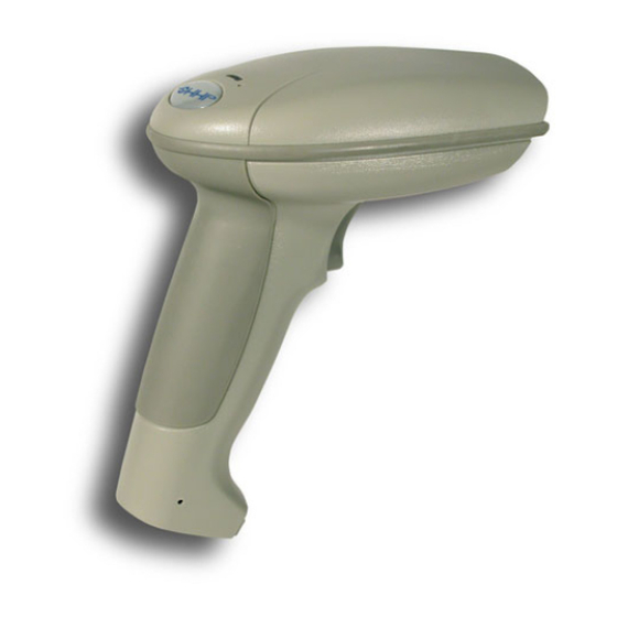
The IMAGETEAM 3800 is a high performance linear imaging scanner from Welch Allyn Data Collection, Inc. The IT3800 marks a new performance level for hand held scanners. Linear imaging technology is defined by a bright and sharply focused aiming line, high resolution imaging, and fast reading speed. The IT3800 is comfortable to hold, easy to use, rugged, and excellent for all general scanning applications. -
Page 8: Keyboard Wedge Connection
A scanner can be connected between the keyboard and PC as a “keyboard wedge,” plugged into the serial port, or connected to a portable data terminal in wand emulation or non decoded output mode. The following is an example of a keyboard wedge connection: 1. -
Page 9: Plug And Play
Plug and Play bar codes provide instant scanner set up for commonly used interfaces. Note: After you scan one of the codes, power cycle the host terminal to have the interface in effect The most common interface is Keyboard Wedge. The following Keyboard Wedge bar code also programs a carriage return (CR) and line feed (LF) suffix. - Page 10 The RS-232 Interface bar code is used when connecting to the serial port of a PC or terminal. The following RS-232 Interface bar code also programs the parameters: Option Setting Baud Rate 9600 bps Parity Even Data Format 7 data bits, parity bit, 1 stop bit (8 bit data) RS-232 Interface In Wand Emulation mode, the scanner decodes the bar code then sends data in the same format as a wand scanner.
- Page 11 Note: The following Retail “Plug and Play” codes are for use with the 3800LR–11 model only. Scan one of the following “Plug and Play” codes to program the IT3800 for IBM 4683 Port 5B, 9B, or 17. Note: After you scan one of the codes, power cycle the cash register to have the interface in effect IBM 4683 Port 5B Interface IBM 4683 Port 9B HHBCR-1 Interface...
- Page 12 Scan one of the following “Plug and Play” codes to program the IT3800 for Generic OCIA, NCR OCIA Short Format (8 bit), NCR OCIA Long Format (9 bit), and Nixdorf OCIA. Note: After you scan one of the codes, power cycle the cash register to have the interface in effect Generic OCIA Interface The Generic OCIA bar code also programs the following prefixes for each...
- Page 13 NCR OCIA Long Format (9 Bit) Interface The NCR OCIA Long Format (9 Bit) bar code also programs the following prefixes for each symbology: Symbology Prefix Symbology Prefix EAN 8 46 46 Code 39 42 31 EAN 13 I 2 of 5 42 32 UPC A Code 128...
-
Page 14: Serial Wedge
The IT3800 uses a USB converter to simulate a USB keyboard. Data flows into applications as if entered from the keyboard. The USB converter is compatible with Apple I–MAC Series and WindowsR 98 and later PCs. Use cable set 42206062–01 to make the USB port connection. To set up the USB communications, find the terminal ID in the Supported Terminal Chart and follow the instructions on page 2–2. - Page 15 IMAGETEAM 3800 scanners are factory programmed for a keyboard wedge interface to an IBM PC AT with a USA keyboard. If this is your interface and you do not need to modify the settings, skip to Section 3 – Output. If you have a different terminal and/or you want to make any keyboard wedge changes, scan the bar code below.
- Page 16 If your interface is not a standard PC AT, refer to the Supported Terminals Chart on page 2–3 and locate the Terminal ID number for your PC. Scan the Terminal ID bar code below, then scan the numeric bar code(s) on the inside back cover of this manual to program the scanner for your terminal ID.
- Page 17 Terminal Model(s) Terminal ID Apple Mac Mac Classic, SE SE30, II (All) 049** Apple Mac Powerbook 5300 Series (Portable PC) 049** VT510, 520, 525 (PC style) VT510, 520, 525 (DEC style LK411) 104 Esprit 200, 400 Heath Zenith PC, AT Vectra HP Vectra PS/2 25, 30, 77DX2...
-
Page 18: Keyboard Country
Terminal Model(s) Terminal ID Telex 88 key 078, 078A, 79, 80, 191, 196, 1191,1192, 1471, 1472, 1476, 1477, 1483 Telex 88 key Data Entry Keyboard Telex 102 key 078, 078A, 79, 80, 191, 196, 1191,1192, 1471, 1472, 1476, 1477, 1483 Telex 122 key 078, 078A, 79, 80, 191, 196, 1191,1192, 1471, 1472, 1476,... -
Page 19: Keyboard Style
This programs keyboard styles, such as Caps Lock and Shift Lock. Default = Regular. Regular is used when you normally have the Caps Lock key off. * Regular Caps Lock is used when you normally have the Caps Lock key on. Caps Lock Shift Lock is used when you normally have the Shift Lock key on. - Page 20 This modifies special keyboard features, such as CTRL+ ASCII codes and Turbo Mode. Control + ASCII Mode On – The scanner sends key combinations for ASCII control characters for values 00–1F. Refer to page 10–1 for CTRL+ ASCII Values. Default = Off Control + ASCII Mode On * Control + ASCII Mode Off Turbo Mode –...
- Page 21 Automatic Direct Connect – Use this selection if you are using a laptop whose keyboard is disabled when you plug in the scanner. This selection can also be used if you have an IBM AT style terminal and the system is dropping characters.
- Page 22 All communication parameters between the scanner and terminal must match for correct data transfer through the serial port using RS-232 protocol. Scan the RS-232 Interface bar code to program the scanner for an RS-232 installation. RS-232 Interface 1. Turn off power to the terminal/computer. 2.
- Page 23 Baud Rate sends the data from the scanner to the terminal at the specified rate. The host terminal must be set for the same baud rate as the scanner. Default = 9600. 1200 2400 4800 * 9600 19200 38400 IMAGETEAM 3800 User’s Guide 2–9...
- Page 24 Data Bits sets the word length at 7 or 8 bits of data per character. If an application requires only ASCII Hex characters 0 through 7F decimal (text, digits, and punctuation), select 7 data bits. For applications which require use of the full ASCII set, select 8 data bits per character.
- Page 25 7 Data, 2 Stop, Parity Mark 7 Data, 2 Stop, Parity Space 8 Data, 1 Stop, Parity Even 8 Data, 1 Stop, Parity None 8 Data, 1 Stop, Parity Odd 8 Data, 1 Stop, Parity Mark 8 Data, 1 Stop, Parity Space IMAGETEAM 3800 User’s Guide 2–11...
- Page 26 RS-232 handshaking is a set of rules concerning the exchange of data between serially communicating devices. Default = RTS/CTS, XON/XOFF and ACK/NAK Off RTS/CTS On * RTS/CTS Off XON/XOFF On * XON/XOFF Off ACK/NAK On * ACK/NAK Off 2–12 IMAGETEAM 3800 User’s Guide...
- Page 27 In Wand Emulation mode, the scanner decodes the bar code then sends data in the same format as a wand scanner. The Code 39 Format converts all symbologies to Code 39. The Same Code Format transmits UPC, EAN, Code 128 and Interleaved 2 of 5 without any changes, but converts all other symbologies to Code 39.
- Page 28 The Transmission Rate is limited by the terminal’s ability to receive data without dropping characters. Default = 25 inches/second. * 25 2–14 IMAGETEAM 3800 User’s Guide...
- Page 29 The Polarity can be sent as standard with black bars high, or reversed with white bars high. Default = Black High. * Black High White High The idle describes the state of the scanner when no data is being transmitted. When in Wand Emulation mode, you must set the scanner’s idle state to match the idle state for the device to which the scanner is connected.
- Page 30 Note: The following Wand Emulation functions are for use with the 3800PDF-12 scanner only. This transmits the PDF417 data in smaller blocks to prevent buffer overflow. Default = 60. * 60 2–16 IMAGETEAM 3800 User’s Guide...
- Page 31 This sets the delay time between data blocks. Default = 50ms. * 50ms 150ms 500ms When this option is turned on, a computed check character is added at the end of the entire message. The check character is the character which when Exclusive-ORed with every preceding character of the message yields a result of 0x00 (00H).
- Page 32 This provides a “wake up” pulse on the sync line from the scanner to a portable terminal. This feature extends battery life of the portable terminal by waking up the terminal only when data is ready to be sent. Bar code data follows the wake up pulse after a 0.2 second delay.
-
Page 33: Scan Rate
Adjusting the scan rate changes the current draw when scanning. The slower the scan rate, the lower the current draw. (The standby current remains the same.) Default = 270 s/s. Note: The chart below applies to the -12 models only. Scan Speed Standby Scanning... - Page 34 Default = Normal. * Normal Beep Short Bip This sets the number of times the same bar code has to be read before it is transmitted to the terminal. Normal uses the default values listed for the symbologies in the Default Charts in Section 10. High doubles the votes used below the threshold.
- Page 35 This sets the time period before the scanner can read the same bar code a second time. Setting a reread delay protects against accidental rereads of the same bar code. Longer delays are effective in minimizing accidental rereads at POS (point of sale). Use shorter delays in applications where repetitive bar code scanning is required.
- Page 36 Default = Manual Trigger Manual Trigger: You must press the scanner trigger to scan. When not scanning, idle power is maintained. * Manual Trigger Manual Trigger, Low Power: The scanner “sleeps,” using only 5 microamps, until the trigger is pulled. When the trigger is pulled, the scanner wakes up and operates at reduced power until there is no triggering for the time set with the Low Power Time Out bar code.
- Page 37 When a bar code is scanned, additional information is sent to the host computer along with the bar code data. This group of bar code data and additional, user-defined data is called a “message string.” The selections in this section are used to build the user-defined data into the message string. Prefix and Suffix characters are data characters that can be sent before and after scanned data.
-
Page 38: To Add A Prefix Or Suffix
STEP 1. Scan the Add Prefix or Add Suffix symbol (pg. 4–4). STEP 2. Determine the 2 digit Hex value from the Symbology Chart (pg. 4–5) for the symbology to which you want to apply the prefix or suffix. STEP 3. Scan the 2 hex digits from the Programming Chart inside the back cover or scan 9, 9 for all symbologies. -
Page 39: To Add A Carriage Return Suffix To All Symbologies
Scan the following bar code if you wish to add a Carriage Return Suffix to all symbologies at once. This action first clears all current suffixes, then programs a carriage return suffix for all symbologies. Add CR Suffix All Symbologies IMAGETEAM 3800 User’s Guide 4–3... - Page 40 Add Prefix Clear One Prefix Clear All Prefixes Add Suffix Clear One Suffix Clear All Suffixes Save Discard 4–4 IMAGETEAM 3800 User’s Guide...
-
Page 41: Symbology Chart
Symbology Chart Code Code Symbology Symbology Value Value Codabar Plessey Code 39 IATA Code 2 of 5 Code 39 PARAF Code 11 Code 128 EAN/JAN Telepen Interleaved 2 of 5 Matrix 2 of 5 Code 93 China Postal Code 2 of 5 PDF417 All Symbologies [ [ Prefix/Suffix entries for specific symbologies override the All Symbologies... -
Page 42: Supported Interface Keys
When this selection is enabled and function codes are contained within the scanned data, the scanner transmits the function code to the terminal. Charts of these function codes are provided in Section 10, Supported Interface Keys. When the scanner is in keyboard wedge mode, the scan code is converted to a key code before it is transmitted. -
Page 43: Intercharacter Delay
Some terminals drop information (characters) if data comes through too quickly. Intercharacter, interfunction, and intermessage delays slow the transmission of data, which increases data integrity. Each delay is composed of a 5 millisecond step. You can program up to 99 steps (of 5 ms each). - Page 44 This is a delay of up to 495 milliseconds (in multiples of 5) placed after the transmission of a particular character of scanned data. You can program up to 99 steps (of 5 ms each) to follow the character you specify. Scan the Delay Length bar code below, then the number of steps for the delay, and the SAVE bar code from the inside back cover.
-
Page 45: Interfunction Delay
This is a delay of up to 495 milliseconds (in multiples of 5) placed between the transmission of each segment of the message string. You can program up to 99 steps (of 5 ms each). Scan the Interfunction Delay bar code below, then scan the number of steps, and the SAVE bar code from the inside back cover. - Page 46 4–10 IMAGETEAM 3800 User’s Guide...
-
Page 47: Data Format Editor
The Data Format Editor selections are used to edit scanned data. For example, you can use the Data Format Editor to insert characters at certain points in bar code data as it is scanned. It is not necessary to use the Data Format Editor. A set of defaults for the data format is already programmed in the scanner. - Page 48 Other Programming Selections Clear One Data Format This deletes one data format for one symbology. If you are clearing the primary format, scan 0. If you are clearing an alternate format, scan 1, 2, or 3, depending on the alternate format you are clearing. Scan the Terminal Type (refer to the Supported Terminals Chart on page 2–3), Code I.D.
- Page 49 Search Commands F8 Search ahead for “xx” character from current cursor position, leaving cursor pointing to “xx” character. Syntax = F8xx (xx stands for the hex value for an ASCII code, see Decimal to Hex to ASCII Conversion chart, page 4–5.) F9 Search back for “xx”...
- Page 50 Enter Data Format Default Data Format Clear One Data Format Clear All Data Formats Save Discard 5–4 IMAGETEAM 3800 User’s Guide...
-
Page 51: Data Formatter
When Data Formatter is turned off, the bar code data is output to the host as read (including prefixes and suffixes). Choose one of the following options. Default = Data Formatter On. * Data Formatter On, but Not Required Data Formatter Off When Data Formatter is required, all input data must conform to an edited format or the scanner does not transmit the input data to the host device. -
Page 52: Alternate Data Formats
Alternate formats allow you “single shot” capability to scan one bar code using a different data format than your primary format. When data formats are programmed (see page 5–1), you must input whether you are programming the primary format, or an alternate format numbered 1, 2, or 3. An alternate format is initiated by scanning one of the 3 alternate format bar codes below. -
Page 53: Secondary Interface
By switching interface cables, the IT3800 scanner can communicate with a portable data terminal (secondary interface), in addition to the host terminal (primary interface). The secondary interface can be programmed at any time. In Wand Emulation mode, the scanner decodes the bar code then sends data in the same format as a wand scanner. - Page 54 Use this selection when connecting to a secondary terminal with integral decoding. This also sets the transmission rate to 36 scans per second and the polarity to white high. Non Decoded Output The Transmission Rate is limited by the terminal’s ability to receive data without dropping characters.
- Page 55 The idle describes the state of the scanner when no data is being transmitted. When in Non Decoded mode, you must set the scanner’s idle state to match the idle state for the device to which the scanner is connected. Default = High. * High You can temporarily disable the secondary interface, but still retain the secondary interface settings in the scanner’s memory by scanning the Disable...
- Page 56 Manual Trigger: You must press the scanner trigger to scan. When not scanning, idle power is maintained. Default = Manual Trigger. * Manual Trigger Automatic Trigger: The scanner scans continuously at full power. Automatic Trigger Manual Trigger, Low Power: The scanner “sleeps,” using only 5 microamps, until the trigger is pulled.
- Page 57 Use this section to program the scanner for Industrial, Retail, and PDF417 Symbology selections. This programming section contains the following menu selections: Codabar Code 128 Code 39 Telepen Interleaved 2 of 5 Code 93 EAN/JAN Code 2 of 5 IATA Code 2 of 5 Plessey Matrix 2 of 5 China Postal Code...
-
Page 58: Codabar
Codabar <Default All Codabar Settings> Codabar * On Start / Stop Characters Start/Stop characters identify the leading and trailing ends of the bar code. You may either transmit, or not transmit Start/Stop characters. Default = Don’t Transmit. * Don’t Transmit Transmit 7–2 IMAGETEAM 3800 User’s Guide... -
Page 59: Check Character
Codabar, continued Check Character Codabar check characters are created using different “modulos.” You can program the scanner to read only Codabar bar codes with Modulo 16 check characters. Default = No Check Character. No Check Character indicates that the scanner reads and transmits bar code data with or without a check character. - Page 60 Codabar, continued Concatenation Codabar supports symbol concatenation. When you Enable concatenation, the scanner looks for a Codabar symbol having a “D” start character, adjacent to a symbol having a “D” stop character. In this case the two messages are concatenated into one with the “D” characters omitted. Default = On. Character: Start Stop Start...
-
Page 61: Message Length
Codabar, continued Message Length The message length selection is used to set the valid reading length of the bar code. You may wish to set the same value for minimum and maximum length to force the scanner to read fixed length bar code data. This helps reduce the chances of a misread. - Page 62 Code 39 <Default All Code 39 Settings> Code 39 * On Start / Stop Characters Start/Stop characters identify the leading and trailing ends of the bar code. You may either transmit, or not transmit Start/Stop characters. Default = Don’t Transmit. * Don’t Transmit Transmit 7–6...
- Page 63 Code 39, continued Check Character No Check Character indicates that the scanner reads and transmits bar code data with or without a check character. When Check Character is set to Validate, but Don’t Transmit, the unit will only read Code 39 bar codes printed with a check character, but will not transmit the check character with the scanned data.
- Page 64 Code 39, continued The message length selection is used to set the valid reading length of the bar code. You may wish to set the same value for minimum and maximum length to force the scanner to read fixed length bar code data. This helps reduce the chances of a misread.
-
Page 65: Code 39 Append
Code 39, continued Code 39 Append This function allows the scanner to append the data from several Code 39 bar codes together before transmitting them to the host computer. When this function is enabled, the scanner stores those Code 39 bar codes that start with a space (excluding the start and stop symbols), and does not immediately transmit the data. -
Page 66: Full Ascii
Code 39, continued Full ASCII If Full ASCII Code 39 decoding is enabled, certain character pairs within the bar code symbol will be interpreted as a single character. For example: $V will be decoded as the ASCII character SYN, and /C will be decoded as the ASCII character #. -
Page 67: Interleaved 2 Of 5
Interleaved 2 of 5 <Default All Interleaved 2 of 5 Settings> Interleaved 2 of 5 * On Check Digit No Check Digit indicates that the scanner reads and transmits bar code data with or without a check digit. When Check Digit is set to Validate, but Don’t Transmit, the unit will only read Interleaved 2 of 5 bar codes printed with a check digit, but will not transmit the check digit with the scanned data. - Page 68 Interleaved 2 of 5, continued The message length selection is used to set the valid reading length of the bar code. You may wish to set the same value for minimum and maximum length to force the scanner to read fixed length bar code data. This helps reduce the chances of a misread.
- Page 69 Code 93 <Default All Code 93 Settings> Code 93 * On The message length selection is used to set the valid reading length of the bar code. You may wish to set the same value for minimum and maximum length to force the scanner to read fixed length bar code data.
-
Page 70: Code 2 Of
Code 2 of 5 <Default All Code 2 of 5 Settings> 2 of 5 * On The message length selection is used to set the valid reading length of the bar code. You may wish to set the same value for minimum and maximum length to force the scanner to read fixed length bar code data. -
Page 71: Iata Code 2 Of
IATA Code 2 of 5 <Default All Code IATA 2 of 5 Settings> IATA 2 of 5 * On The message length selection is used to set the valid reading length of the bar code. You may wish to set the same value for minimum and maximum length to force the scanner to read fixed length bar code data. -
Page 72: Matrix 2 Of
Matrix 2 of 5 <Default All Matrix 2 of 5 Settings> Matrix 2 of 5 * On The message length selection is used to set the valid reading length of the bar code. You may wish to set the same value for minimum and maximum length to force the scanner to read fixed length bar code data. -
Page 73: Check Digits Required
Code 11 <Default All Code 11 Settings> Code 11 * On Check Digits Required This option sets whether 1 or 2 check digits are required with Code 11 bar codes. Default = Two Check Digits. One Check Digit * Two Check Digits IMAGETEAM 3800 User’s Guide 7–17... - Page 74 Code 11, continued The message length selection is used to set the valid reading length of the bar code. You may wish to set the same value for minimum and maximum length to force the scanner to read fixed length bar code data. This helps reduce the chances of a misread.
-
Page 75: Code 128
Code 128 <Default All Code 128 Settings> Code 128 * On If function characters are turned off, function codes are not sent with bar code data. Refer to Hex ASCII Conversion Chart on page 4–5 for function codes. Default =Off. * Off When enabled, the scanner substitutes a <GS>... - Page 76 Code 128, continued The message length selection is used to set the valid reading length of the bar code. You may wish to set the same value for minimum and maximum length to force the scanner to read fixed length bar code data. This helps reduce the chances of a misread.
-
Page 77: Telepen
Telepen <Default All Telepen Settings> Telepen * On Telepen Output Using AIM Telepen Output, the scanner reads symbols with start/stop pattern 1 and decodes them as standard full ASCII (start/stop pattern 1). When Original Telepen Output is selected, the scanner reads symbols with start/stop pattern 1 and decodes them as compressed numeric with optional full ASCII (start/stop pattern 2). - Page 78 Telepen, continued The message length selection is used to set the valid reading length of the bar code. You may wish to set the same value for minimum and maximum length to force the scanner to read fixed length bar code data. This helps reduce the chances of a misread.
-
Page 79: Check Digit
UPC A <Default All UPC A Settings> UPC A * On Check Digit This selection allows you to specify whether the check digit should be transmitted at the end of the scanned data or not. Default = On. * On Number System The numeric system digit of a UPC symbol is normally transmitted, but the unit can be programmed so it will not transmit it. - Page 80 UPC A, continued Addenda This selection adds 2 or 5 digits to the end of all scanned UPC A data. Default = Off for both 2–Digit and 5–Digit Addenda. 2–Digit Addenda * Off 5–Digit Addenda * Off 7–24 IMAGETEAM 3800 User’s Guide...
-
Page 81: Addenda Required
UPC A, continued Addenda Required When Addenda Required is set to on, the scanner will only read UPC A bar codes that have addenda. Default = Off. Addenda Required * Off Addenda Separator When this feature is on, there is a space between the data from the bar code and the data from the addenda. - Page 82 UPC E <Default All UPC E Settings> Most UPC bar codes lead with the 0 number system. For these codes, use the UPC E0 selection. If you need to read codes that lead with the 1 number system, use the UPC E1 selection. Default = On (UPC E0) and Off (UPC E1). UPC E0 * On UPC E1...
- Page 83 UPC E, continued Check Digit Check Digit specifies whether the check digit should be transmitted at the end of the scanned data or not. Default = On. * On Number System The numeric system digit of a UPC symbol is normally transmitted, but the unit can be programmed so it will not transmit it.
- Page 84 UPC E, continued Addenda Required When Addenda Required is set to on, the scanner will only read UPC E bar codes that have addenda. Default = Off. * Off Addenda Separator When this feature is on, there is a space between the data from the bar code and the data from the addenda.
-
Page 85: Ean/Jan 13
EAN/JAN 13 <Default All EAN/JAN 13 Settings> EAN/JAN 13 * On Check Digit This selection allows you to specify whether the check digit should be transmitted at the end of the scanned data or not. Default = On. * On Addenda This selection adds 2 or 5 digits to the end of all scanned EAN/JAN 13 data. - Page 86 EAN/JAN 13, continued 5–Digit Addenda * Off Addenda Required When Addenda Required is set to on, the scanner will only read EAN/JAN 13 bar codes that have addenda. Default = Off. * Off Addenda Separator When this feature is on, there is a space between the data from the bar code and the data from the addenda.
-
Page 87: Ean/Jan 8
EAN/JAN 8 <Default All EAN/JAN 8 Settings> EAN/JAN 8 * On Check Digit This selection allows you to specify whether the check digit should be transmitted at the end of the scanned data or not. Default = On. * On Addenda This selection adds 2 or 5 digits to the end of all scanned EAN/JAN 13 data. - Page 88 EAN/JAN 8, continued 5–Digit Addenda * Off Addenda Required When Addenda Required is set to on, the scanner will only read EAN/JAN 13 bar codes that have addenda. Default = Off. Addenda Required * Off Addenda Separator Default = On. * On 7–32 IMAGETEAM 3800 User’s Guide...
- Page 89 <Default All MSI Settings> * Off Check Character Different types of check characters are used with MSI bar codes. You can program the scanner to read only MSI bar codes with Type 10 or Type 11 check characters. Default = Validate Type 10, but Don’t Transmit. When Check Character is set to Validate and Transmit, the scanner will only read MSI bar codes printed with the specified type check character, and will transmit this character at the end of the scanned data.
- Page 90 MSI, continued The message length selection is used to set the valid reading length of the bar code. You may wish to set the same value for minimum and maximum length to force the scanner to read fixed length bar code data. This helps reduce the chances of a misread.
-
Page 91: Plessey
Plessey <Default All Plessey Settings> Plessey * Off The message length selection is used to set the valid reading length of the bar code. You may wish to set the same value for minimum and maximum length to force the scanner to read fixed length bar code data. This helps reduce the chances of a misread. -
Page 92: China Post Code
China Post Code <Default All China Post Code Settings> China Post Code * Off The message length selection is used to set the valid reading length of the bar code. You may wish to set the same value for minimum and maximum length to force the scanner to read fixed length bar code data. - Page 93 Note:The following Symbology selections are for use with the 3800PDF–12 scanner only. PDF417 <Default All PDF417 Settings> PDF417 * On The message length selection is used to set the valid reading length of the bar code. You may wish to set the same value for minimum and maximum length to force the scanner to read fixed length bar code data.
-
Page 94: Scan Diagnostics
Note:The following Symbology selections are for use with the 3800PDF–12 scanner only. Turning Show GLI Blocks on causes GLI commands to be issued where located within their encoded data sequences. When on, the “\” is used as an escape character and natural occurrences of “\” in data are replaced by “\\”. Default = Off. -
Page 95: Cloning Procedure
The cloning procedure reprograms the software in the “destination” scanner’s memory with software from the “source” scanner. Before using this procedure, determine which scanner will be the source (the scanner containing the desired software). The IMAGETEAM 3800 supports cloning and can act as the source device. - Page 96 8–2 IMAGETEAM 3800 User’s Guide...
-
Page 97: Visual Menu Operations
Visual Menu provides the ability to configure a scanning device by connecting the scanner to the com port of a PC. Visual Menu allows you to download upgrades to a scanner’s firmware, change programmed parameters, and create and print programming bar codes. Using Visual Menu, you can even set up the configuration for a scanner which is not attached to your PC. - Page 98 Access the Welch Allyn Data Collection, Inc. web site at http://dcd.welchallyn.com. Click on the Support button, then click on the Software Download button. When prompted, enter the user name: pumpkin and the password: pie Locate the listing for Visual Menu. Click on the yellow Download button.
- Page 99 The following Keyboard Function Code, Hex/ASCII Value, and Full ASCII “CTRL”+ relationships apply to all terminals that can be used with the scanner. Function Code HEX/ASCII Value Full ASCII “CTRL” + IMAGETEAM 3800 User’s Guide 10–1...
- Page 100 The last five characters in the Full ASCII “CTRL”+ column ( [ \ ] 6 - ), apply to US only. The following chart indicates the equivalents of these five characters for different countries. Country Codes United States Belgium < Scandinavia <...
- Page 101 IBM AT/XT and IBM, DDC, PS/2 Compatibles, IBM XTs and Memorex Telex, Supported Interface Keys WYSE PC/AT Compatibles Harris* Reserved Reserved Reserved Enter (KP) CR/Enter Enter Cap Lock Caps Lock ALT make Reserved ALT break Reserved CTRL make Reserved CTRL break Reserved CR/Enter CR/Enter...
- Page 102 IBM, Memorex Memorex Supported Interface Keys Telex (102)* Telex (88)** Reserved Reserved Enter Enter PF10 PF11 PF12 Reserved Reserved New Line New Line Field Forward Field Forward Reserved Tab/Field Forward Field Forward Delete Delete Field Exit New Line Insert Insert Clear Erase Error Reset...
- Page 103 Esprit 200, 400 Esprit 200, 400 Esprit 200, 400 Supported Interface Keys ANSI ASCII Reserved Reserved Reserved New Line New Line New Line New Line New Line New Line Delete New Line New Line New Line Insert Escape Escape Escape Insert Insert Home...
- Page 104 10–6 IMAGETEAM 3800 User’s Guide...
- Page 105 This selection allows you to turn on transmission of a Code I.D. before the decoded symbology. (See the Symbology Chart on page 4–5 for the single character code that identifies each symbology.) This action first clears all current prefixes, then programs a Code I.D.
- Page 106 11–2 IMAGETEAM 3800 User’s Guide...
-
Page 107: Keyboard Modifiers
If you aren’t sure what programming options are in your scanner, or you’ve changed some options and want the factory settings restored, scan the Factory Default Settings bar code below. Factory Default Settings The following chart lists the factory default settings (indicated by an asterisk (*) on the programming pages). -
Page 108: Pdf417 Wand Emulation
Parameter Default Page PDF417 Wand Emulation Selections Data Block Size ..........2–16 Data Between Blocks . - Page 109 Parameter Default Page Code 39 Selections Code 39 ........... . 7–6 Start/Stop .
- Page 110 Parameter Default Page Matrix 2 of 5 Selections Matrix 2 of 5 ..........7–16 Message Length .
- Page 111 Parameter Default Page UPC E UPC E0 ........... . 7–26 UPC E1 .
- Page 112 Parameter Default Page Plessey Selections Plessey ........... . 7–35 Message Length .
- Page 113 Dimensions Height ....6.0 inches (15.2 cm) Length ....5.3 inches (13.5 cm) Weight .
- Page 114 Laser Output only (Laser Compatible Bar Image) Conventional laser data format is provided at the modular connector in the scanner handle. Interface cables are terminated with a 10 pin modular plug (P1) and a 9 pin Type D (squeeze to release) connector (P2) that is compatible with all Welch Allyn Data Collection, Inc.
- Page 115 Keyboard Wedge Decoded output data format provided at 10 pin RJ41 modular connector (in scanner handle). See chart below. 10 Pin RJ41 Modular Connector Signal Function Cord Shield Prog 1 Ground Supply Ground Tclock Terminal Clock Tdata Terminal Data +5VDC 5 Volt Power Connection Kdata Keyboard Data...
- Page 116 Wand Emulation Conventional wand data format provided at 10 pin RJ41 modular connector (in scanner handle). See chart below. 10 Pin Modular Plug 9 Pin Type D Female P1 connects to the P2 connects to scanner handle. your terminal. Pin 1 Pin 10 View A–A Signal...
- Page 117 3800LR-12 Decoded output data format provided at 10 pin RJ41 modular connector (in scanner handle). See chart below. 10 Pin RJ41 Modular Connector Signal Function Braid Cord Shield Prog Tied to 5 Volt Power Ground Supply Ground Receive Data – Serial Data to Scanner Transmit Data –...
- Page 118 13–6 IMAGETEAM 3800 User’s Guide...
- Page 119 IT3800LR–11 reading good quality linear bar codes IT3800LR–12 reading good quality linear bar codes IMAGETEAM 3800 User’s Guide 14–1...
- Page 120 Scan Maps, continued IT3800VHD–12 reading good quality linear bar codes IT3800PDF–12 reading good quality, 3:1 aspect ratio PDF417 bar codes 14–2 IMAGETEAM 3800 User’s Guide...
- Page 121 Scan Maps, continued IT3800PDF–12 reading good quality linear bar codes IMAGETEAM 3800 User’s Guide 14–3...
- Page 122 14–4 IMAGETEAM 3800 User’s Guide...
- Page 123 Welch Allyn Data Collection, Inc. provides service for all its products through a service center located at its manufacturing facilities in Skaneateles, New York. To obtain warranty or non–warranty service, return the unit to Welch Allyn (postage paid) with a copy of the dated purchase record attached. Please contact the Welch Allyn Data Collection, Inc.
-
Page 124: Technical Support
For service in Asia, please contact your Welch Allyn representative (at address below) or your local distributor. Welch Allyn, Hong Kong Office 10/F Tung Sun Commercial Centre 194–200 Lockhart Road Wanchai, Hong Kong Telephone: Int+852–2511–3050 or 2511–3132 Fax: Int+852–2511–3557 If you need assistance installing or troubleshooting your scanner, please call your Distributor or the nearest Welch Allyn technical support office. - Page 125 Welch Allyn Data Collection, Inc., hereby warrants its products to be functional and free from manufacturing defects at the time of delivery. Welch Allyn Data Collection, Inc. further warrants that it will replace or repair, at its option, any unit that fails to perform according to Welch Allyn’s published specifications during a period of five (5) years from the time of shipment by Welch Allyn Data Collection, Inc.
- Page 126 15–4 IMAGETEAM 3800 User’s Guide...
- Page 127 This device complies with part 15 of the FCC Rules. Operation is subject to the following two conditions: (1) this device may not cause harmful interference, and (2) this device must accept any interference received, including interference that may cause undesired operation. This equipment has been tested and found to comply with the limits for a Class B digital device pursuant to part 15 of the FCC Rules.
- Page 128 The CE mark on the product indicates that the system has been tested to and conforms with the provisions noted within the 89/336/EEC Electromagnetic Compatibility Directive and the 73/23/EEC Low Voltage Directive. For further information, please contact: Welch Allyn Ltd. 1st Floor Dallam Court Dallam Lane Warrington, Cheshire WA2 7LT...
- Page 129 IMAGETEAM 3800 User’s Guide...
- Page 130 IMAGETEAM 3800 User’s Guide...
- Page 131 Save Discard...
- Page 132 Code 39 Matrix 2 of 5 TEST–SHEET Code 128 6543210 Codabar CODE 128 EAN 13 0013557900 Code 93 9 780330 290951 Interleaved 2 of 5 123456–9$ Code 2 of 5 1234567890 UPC A with 5 digit addenda 123456 56098 PDF417 0 12345 67890 5 Car Registration Data Collection, Inc.
Need help?
Do you have a question about the IMAGETEAM 3800 and is the answer not in the manual?
Questions and answers