Table of Contents
Advertisement
Quick Links
f
Save ThisManual
For FutureReference
owners
manual
MODEL NO.
tt3.t98110
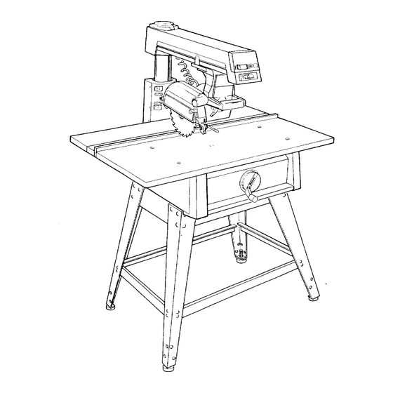
10" RADIAL SAW
WITH LEG SET
S_rial
Number
Model and s_rial numbers
may b_ found
on the
backside
of the bas_.
You should record both
model and s_ial number
in a safe place for future
USC.
I
CAUTION:
READALL
INSTRUCTIONS
CAREFULLY
CRRFTSMRN
10-INCH RADIAL SAW
• assembly
• operating
• repair parts
Sold by SEARS, ROEBUCK AND CO., Chicago, IL.60684 U.S.A.
Part No. SP50fl 7
Printed in U,S.A.
Advertisement
Table of Contents
Troubleshooting

Related Manuals for Craftsman 113.198110


Summary of Contents for Craftsman 113.198110
- Page 1 Save ThisManual For FutureReference owners manual MODEL NO. tt3.t98110 10" RADIAL SAW WITH LEG SET S_rial CRRFTSMRN Number Model and s_rial numbers may b_ found on the backside of the bas_. You should record both model and s_ial number in a safe place for future 10-INCH RADIAL SAW USC.
- Page 2 FULL ONE YEAR WARRANTY ON CRAFTSMAN RADIAL If within year from date of purchase, this Craftsman Radial fails to a defect in material workmanship, Sears will repair it, free of charge. WARRANTY SERVICE AVAILABLE SIMPLY CONTACTING NEAREST SEARS SERVICE CENTER/DEPARTMENT THROUGHOUT THE UNITED STATES.
- Page 3 additional instructions for radial saws BEFORE USING SAW: WARNING: TO AVOID MISTAKES THAT COULD expected contact with the workpiece, fence, RESULT IN SERIOUS, PERMANENT INJURY, DO table or part of your body. NOT CONNECT POWER CORD UNTIL THE FOL- LOWING STEPS HAVE BEEN SATISFACTORILY BEFORE EACH...
- Page 4 while the cutting tool is rotating. The rotating of a second is sufficient to inflict severe, permanent tool could cut and throw anything hitting injury. blade causing the saw to unexpectedly come If your saw makes an unfamiliar noise or if it forward.
- Page 5 --To avoid kickbacks never feed a workpiece from the nose side (opposite the sawdust exhaust chute) of the guard. Note warning through with another piece (butting _'-_ guard. second piece against trailing end of piece being ",_ cut) even if of the same thickness, -- To keep control of you r workpiece, never...
- Page 6 provideadditional g uardingfromcontactwiththe --Always return carriage to the full rearward front of the blade. position behind fence at the completion each crosscut type operation. Never remove your --To preventthe cutting tool from grabbingthe hand from the yoke handle unless the carriage table or workpieceand beingpropelledtoward in this position.
- Page 7 Sawblade Path Outrip Positioning the blade parallel to the fence with the The area of the workpiece or table top directly in line with either the travel of the blade or the part of the motor toward the rear of the saw producing maxi- workpiece which...
- Page 8 It is recommended that you have a qualified electri- 4. Frequent "blowing" of fuses or tripping of circuit cian replace the two prong outlet with a properly breakers may result grounded three prong outlet. (a) MOTOR IS OVERLOADED - Overloading occur if you feed...
- Page 9 unpacking and preassembly WARNING: TO AVOID INJURY FROM UNEXPECT- Item Description Qty. Basic Saw Assembly ....ED STARTING OR ELECTRICAL SHOCK, DO NOT Leg ........PLUG THE POWER CORD INTO A SOURCE Stiffener Lower ......POWER UNTIL ALL ASSEMBLY AND ALIGNMENT Stiffener Leg ......
- Page 10 NOTE: Loose Parts Assembly Numbers refer to three digits, underlined in example below, the I.D. Number printed on each bag or carton. X04507661H000 Bag of Loose Parts #507529 Containing Following Items: Clamp, Table ......Nut, Tee ......Screw, Cup Point Set 1/4-20 x 7/8 ..Washer 21/64 x 9/16 x 1/16 ...
- Page 11 contents Page Page Location and Function of Controls .... Guarantee ........Basic Saw Operations ......General Safety Instructions for Power Tools ..Additional Safety Instructions for Radial Saws .. 3 Adjustments to Compensate for Wear ..Glossary of Terms for Woodworking ...
- Page 12 4. Put leg set in area intended for use of saw. With a 7/16" wrench or socket, securely tighten bolts. Adjust leveling feet. WARNING: TO AVOID INJURY FROM UNEXPECT- ED SAW OR WORK MOVEMENT, LEVELING FEET MUST BE ADJUSTED SO THAT SAW DOES NOT ROCK.
- Page 13 ATTACHING TRIM CAPS & TRIM LEDGE 1. Locate the two (2) trim caps, the trim ledge, and from loose parts bag 498 four (4) sheet metal type "B" #10 x 1 and six (6) type BT screws 1/4 x 1/2. 2.
- Page 14 MOUNTING MOTOR 1. Remove blade guard. Locate arbor wrenches and remove the blade. l/'f ....CAUTION: Do not attempt to mount the motor until the blade guard and blade have been removed. 2. Elevate the arm approximately 2 inches to remove shipping pad.
- Page 15 (b) If column moves front to rear within LOCKWASHER column support, tighten the four (4) bolts, TABLE MOUNTING with a 9/16 socket and extension, located SUPPORT CHANNEL TABLE MOUNTING SUPPORT CHANNEL through holes in rear column support cover until movement disappears. Elevation should SCREWS be smooth...
- Page 16 8. Recheck both support channels to make sure that tightening screws did not affect the accuracy of the adjustment. 9. Elevate saw and return motor to horizontal posi- tion to provide clearance for installation of front (work) table. INSTALLATION OF FRONT (WORK) FRONT TABLE ..
- Page 17 STEP THREE Squaring Crosscut Travel NOTE: This adjustment helps ensure blade accurately travels square to the rip fence. SHAFT 1. Index arm at 0° miter and lock. 2. Install saw blade as shown. Motor shaft has left handed threads - turn nut counterclockwise tighten.
- Page 18 (f) Set miter indicator on 0 ° position as shown. STEP FOUR Squaring Saw Blade to (Work) Table RIPLOCK HANDLE_ NOTE: If alignment procedure step two was oerformed, this adjustment cannot be accomplished. 1. Place a framing square on the table with the short against blade.
- Page 19 STEP FIVE Squaring Blade to Rip Fence NOTE: If alignment procedure steps three and four were not performed, this adjustment step cannot be "SWIVEL accomplished. This adjustment helps avoid binding (kickbacks) or splintering of wood surface, or burn- LOCK HANDLE ing of the kerf.
- Page 20 Unlock the bevel lock handle and loosen the two cap screws located thru the rear of the motor support (see illustration). A 1/8" hex "L" wrench is needed to loosen these screws. Lift or lower the rear of the motor support until the gap between the blade and square dis- appears.
- Page 21 STEP SEVEN Measure 2" from rip fence to nearest tooth on the blade and lock rip lock handle. Installing and Adjusting Rip Scale Indicators Adjust "out rip" scale indicator by sliding until NOTE: The rip scales and pointers are intended to indicator line reads 2 inches on the upper of the be used for quick settings.
- Page 22 Handle can be folded in when not in use, 2. Angle of Cut (Miter) Proper Indexing Method - Experienced operators woodworking equipment such as this Craftsman Radial Saw, acquire the habit of indexing in one direction only, whenever a new setting is made...
- Page 23 5. Blade Angle (Bevel) a. A single bevel lock handle is used in angular positioning indexing of the motor, provide the desired saw blade (bevel) angle. b. The bevel lock handle controls the angular position of the motor with respect to horizontal. The bevel lock handle automatically indexes the motor at 0 °, 45 °...
- Page 24 8. Blade Guard and Anti-Kickback/Spreader Assembly - Positioning for Ripping. GUARD CLAMP SCREW WARNING: NEVER POSITION THE GUARD ANTI-KICKBACK/SPREADER ASSEMBLY WITH THE SAW RUNNING. NEVER POSITION THE ANTI- KICKBACK/SPREADER ASSEMBLY BY GRASPING PAWLS SPREADER. TO MAINTAIN SPREADER ALIGNMENT, USE THE TAB LOCATED ON THE ANTI-KICKBACK BAR.
- Page 25 basic saw operation WARNING: TO AVOID MISTAKES THAT COULD CAUSE SERIOUS PERMANENT INJURY, OBSERVE ALL THE FOLLOWING INSTRUCTIONS IN ADDI- TION TO THOSE ON PAGES 2-6. Basic saw operations are summarized in six cate- gories, explained illustrated in the following paragraphs.
- Page 26 Make sure the arbor nut is snug. Clamp the guard in a horizontal position. Hold work firmly against table and fence. avoid tipping or throwing of workpieces thicker than the fence is high, install a higher fence (at least workpiece thickness).
- Page 27 rectangular frame. The radial arm is set to a desired angle of cut, swivel bevel settings at 0 ° and locked. The workpiece being cut is positioned held firmly against the fence and the carriage pulled forward along radial just enough complete the cut.
- Page 28 board against the fence must be straight and will not catch on kerfs in the fence - for workpieces thicker than the fence is high, install a higher fence (at least the thickness of the workpiece). NEVER RIP "FREEHAND" (without aid offence).
- Page 29 OPERATION NO. 5- OUT-RIPPING IN-RIPPING 1. Ripping is the process of sawing the workpiece along its length by feeding it into the sawblade when using fence as a guide positioning device to obtain the desired width cut. The sawblade is parallel to fence.
- Page 30 OPERATION NO. 6 - BEVEL RIPPING Bevel ripping is either in-ripping or out-ripping described above, except the saw blade is tilted out of perpendicular to the saw table surface. The radial arm is indexed at 0 ° and locked, the bevel is set to the desired bevel...
- Page 31 AUXILIARY FENCE FORMOLDING To use the molding head with the arm in the 0° AUXILIARY FENCE SPACER TABLE crosscut position an auxiliary fence must be used. WARNING: IF THE AUXILIARY FENCE IS NOT USED WHEN THE SAW ARM IS IN THE0 ° CROSS- REAR TABLE CUT POSITION, THE MOLDING...
- Page 32 5. Adjustmentis completewhenboth lockingand indexing functions areworkingproperly. R eplace motorsupportcover. ADJUSTING SWIVEL LOCK HANDLE This handle provides a friction lock between upper face of the yoke and the bottom face of the carriage. It should eliminate any play or rotation between these two parts when locked.
- Page 33 ADJUSTING CARRIAGE BEARINGS The carriage should roll freely but with some resist- ance entire length of travel. test bearing looseness, perform the following steps. 1. Place yoke in either the in-rip or out-rip position. 2. Push the carriage back against the rear stop.
- Page 34 2. With a 3/16 inch hex "L" wrench find the 1/4-20 hex socket cap screw through the hole in the rear arm cover. To tighten turn the wrench clockwise approximately 1/4 turn. 3. Lock the miter lock handle and try again to move the arm.
- Page 35 trouble-shooting HA VE YOU FOLLO WED ALL SIX STEPS ALIGNMENT PROCEDURE? IF YOU HAVE FOLLOWED THEM IN THEIR PROPER SEQUENCE, CANNOT EXPECT A CCURA TE CUTTING RESULTS. In addition to the proper alignment of your saw, you THIS EDGE OF BOARD must also become familiar...
- Page 36 FINISH FINISH 1. RADIAL SAW DOES NOT MAKE ACCURATE 0° SQUARE SQUARE or 45 ° MITER CROSSCUTS. a. Looseness between column tube and column support. Align as described in Alignment Procedure Section Step One. b. Crosscut travel not properly adjusted. Refer to Step Three...
- Page 37 4. SAW KERF (CUT EDGE) OF STOCK ROUGH -TOOTH MARKS LEFT EDGE FENCE KERF. ROUGH KERF _.J.._--WIDE CUT-----_ NOTE: This condition is commonly called "HEEL". a. Crosscutting or Miter Cutting. --_EDGE (KERF)_-__ "Heeling" will tend to slide workpiece along guide fence, as the is being...
- Page 38 9. CLAMPING FORCE SUFFICIENT MITER ANGLES OTHER THAN 45 ° . a. Miter Lock Handle requires Adjustment. Refer to Adjusting Miter Lock Handle in Adjust- ments to Compensate for Wear Section. 10. CLAMPING FORCE SUFFICIENT BEVEL ANGLES OTHER THAN 45 ° . a.
- Page 39 MOTOR TROUBLE-SHOOTING CHART NOTE: Motors used on wood-working tools particularly susceptible to the accumulation sawdust and wood chips and should be blown out or "vacuumed" frequently to prevent interference with normal motor ventilation. TROUBLE PROBABLE CAUSE SUGGESTED REMEDY otor will not run. 1.
- Page 40 Swivel to in-rip or out-rip for easy access to the swivel index When you receive your new Craftsman radial saw, it pin. Bevel saw to 45 ° and bevel index pin can be requires no lubrication.
- Page 41 A light film of oil should be wiped on the face of the column tube to lubricate the fit between the column tube and column support. The thread on the elevation shaft assembly can be lubricated through the oil hole in the center of the radial arm cap.
- Page 42 PARTS LIST FOR CRAFTSMAN 10" RADIAL MODEL NO. 113.198110 Always order by Part Number - Not by Key Number (SEE FIG. (SEE FIG. (SEE FIG. (SEE FIG. (SEE FIG. (SEE FIG. FIGURE...
- Page 43 PARTS LIST FOR CRAFTSMAN 10" RADIAL MODEL NO. 113.198110 Always order by Part Number - Not by Key Number FIGURE Part Part Description Description STD601103 816115 *Screw, Pan Rec. Cord with Plug Type T 10-32 x 3/8 Base and Column...
- Page 44 PARTS LIST FOR CRAFTSMAN 10" RADIAL MODEL NO. 113.198110 Always order by Part Number - Not by Key Number 30 29 FIGURE...
- Page 45 PARTS LIST FOR CRAFTSMAN 10" RADIAL MODEL NO. 113.198110 Always order by Part Number - Not by Key Number FIGURE 2 - BASE COLUMN ASSEMBLY Part Part Description Description 815707 815857-1 Handwheel Screw, Hex Washer 804182 3/8-16 x 1-1/2 *Ring,...
- Page 46 PARTS LIST CRAFTSMAN 10" RADIAL MODEL 113.198110 Always order by Part Number - Not by Key Number 1 t 3 MOTOR CORD FIGURE...
- Page 47 PARTS LIST FOR CRAFTSMAN 10" RADIAL SAW MODEL NO. 113.198110 Always order by Part Number - Not by Key Number FIGURE 3 - YOKE MOTOR ASSEMBLY Part Part Description Description 815803 17 815685 Cap, Motor Support Cover, Yoke 810214-2 18 815788 Screw, Low Hd.,...
- Page 48 PARTS LIST FOR CRAFTSMAN 10" RADIAL MODEL NO. 113.198110 Always order by Part Number - Not by Key Number FIGURE...
- Page 49 PARTS LIST FOR CRAFTSMAN 10" RADIAL MODEL NO. 113.198110 Always order by Part Number - Not by Key Number FIGURE 4 - YOKE ASSEMBLY Part Part Description Description 810214-3 Screw, Low Hd. STD541231 *Nut, Hex Jam 5/16-18 Cap 5/16-18 x 7/8...
- Page 50 PARTS LIST FOR CRAFTSMAN 10" RADIAL MODEL NO. 113.198110 Always order by Part Number - Not by Key Number FIGURE 5 - ARM ASSEMBLY 13 13 Part Part Description Description 815688 i816113 Arm, Radia! Switch, Locking ;815863 815809 Cable Key, Switch...
- Page 51 PARTS LIST FOR CRAFTSMAN 10" RADIAL MODEL NO. 113.198110 Always order by Part Number - Not by Key Number FIGURE GUARD ASSEMBLY 18 19._ Part Part Description Description 816264 Guard STD581050 *Ring, Retaining 120399 6327O *Nut, Square 5/16-18 Spreader 63258...
- Page 52 PARTS LIST FOR CRAFTSMAN 10" RADIAL MODEL NO. 113.198110 Always order by Part Number - Not by Key Number FIGURE 7 - TABLE ASSEMBLY Part Description 815794 Table, Rear 815755 Table Spacer 63432 Fence, Rip 815796 Table, Front *Standard Hardware Item may be Purchased Locally.
- Page 53 PARTS LIST CRAFTSMAN 10" RADIAL MODEL 113.198110 Always order by Part Number - Not by Key Number FIGURE 8 - LEG L____ Part Description 815918 Stiffener, 815910 815909 Stiffener, Lower STD541250 *Nut Hex Jam 1/2-13 803835 Foot, Leveling 805589-5 Screw Truss Hd. 1/4-20 x 1/2...
- Page 54 NOTES...
- Page 55 NOTES...
- Page 56 owners 10.INCH RADIAL SAW manual SERVICE Now that you have purchased your flO-inch radial saw, should a need ever exist for repair paris or service, simply contact Sears Service Center and most Sears, Roebuck and Co. stores. Be sure to provide all pertinent facts when you call or visit.
Need help?
Do you have a question about the 113.198110 and is the answer not in the manual?
Questions and answers