Table of Contents
Advertisement
Available languages
Available languages
Owner's Manual
CRRI:TSMRW
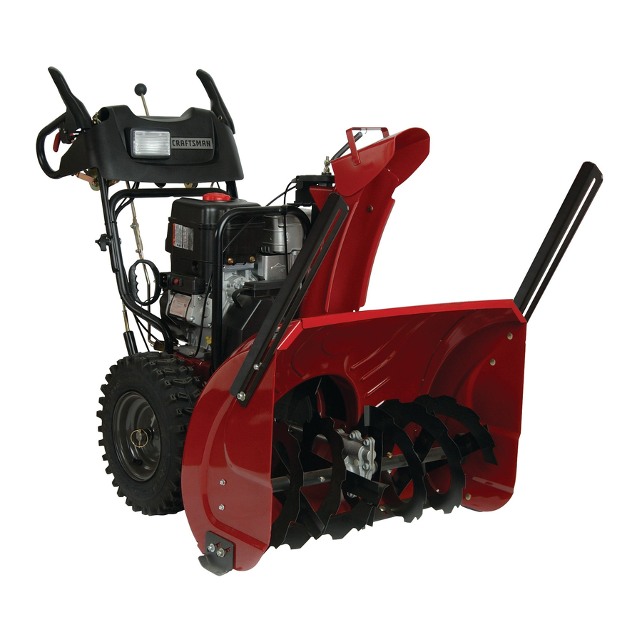
SNOW THROWER
1450 Series Briggs and
Power-Propelled
30" Two-Stage
Model No.
917.881060
• EspaSol, p. 21
CAUTIO
."
Read and follow all
Safety Rules and Instructions
before operating this equipment
Stratton Engine
Sears, Roebuck and Co., Hoffman Estates, IL 60179 U.S.A.
Visit our Craftsman
website:
www.sears.com/craftsman
Advertisement
Table of Contents

Related Manuals for Craftsman 917.881060


Summary of Contents for Craftsman 917.881060
- Page 1 1450 Series Briggs and Power-Propelled 30" Two-Stage Model No. 917.881060 • EspaSol, p. 21 CAUTIO ." Read and follow all Safety Rules and Instructions before operating this equipment Sears, Roebuck and Co., Hoffman Estates, IL 60179 U.S.A. Visit our Craftsman website: www.sears.com/craftsman...
- Page 2 IMPORTANT Safe Operation Practices for Walk=Behind Snow Throwers This snow thrower is capable of amputating hands and feet and throwing objects. Failure to observe the following safety instructions could result in serious injury. WARNING: Snow throwers have ex- & Look for this symbol to point out im- posed rotating parts, which can cause portant safety precautions.
- Page 3 6. When cleaning, repairing o rinspecting thesnowthrower, Clearing a Clogged Discharge Chute stoptheengine andmakecertain thecollector/impel- Hand contact with the rotating impeller inside the discharge ler and all movingpartshavestopped.Disconnect chute is the most common cause of injury associated with thesparkplugwireandkeepthewireawayfromthe snow throwers. Never use your hand to clean out the dis- plug.
- Page 4 CRAFTSMAN P ROFESSIONAL LIMITED WARRANTY Two Years on Snow Thrower Whenoperated andmaintained a ccording t oallsupplied instructions, ifthissnow thrower f ailsdueto a defectin material or workmanship within twoyearsfromthedateor purchase, call1-800-4-MY-HOME® to arrange forfree repair. Thiswarranty a pplies foronlyoneyearfromthedateof purchase ifthissnow thrower i s everusedforcommercial or rental p urposes.
- Page 5 PARTS PACKED SEPARATELY I CARTON (1) MULTi= (1) FUEL STABiLiZER PACKET WRENCH START (1) POWER CORD (2) SAFETY iGNiTiON KEYS (1) AUGER CONTROL (1) TRACTION DRIVE CONTROL ROD _ (1) DISCHARGE CHUTE EXTRA SHEAR BOLTS AND NUTS © (2) SHEAR BOLTS 1/4=20 x 1=3/4 (2) SPACERS (2) LOCKNUTS...
- Page 6 RE-O ERATION Read these instructions and this manual in its entirety before you attempt to assemble or operate your new snow thrower. Reading the entire manual will familiar= ize you with the unit, which will assist you in assembly, operation and maintenance of the product.
- Page 7 RE-O ERATION INSTALL TRACTION DRIVE CONTROL ROD INSTALL AUGER CONTROL ROD (See Figs. 5 and 6) (See Figs. 3 and 4) The auger control rod has the short loop on the end of the spring as shown. The traction drive control rod has the long loop on the end of the spring as shown.
- Page 8 BLY / RE..O ERATION iNSTALL CHUTE DEFLECTOR REMOTE CONTROL iNSTALL DISCHARGE CHUTE / CHUTE ROTATOR HEAD (See Fig. 7) (See Figs. 8 and 9) Install remote cable bracket to discharge chute with NOTE: The multi-wrench provided in your parts bag may 5/16-18 carriage bolt and 5/16-18 Iocknut as shown, be used to install the chute rotator head, Tighten securely,...
- Page 9 OPERATION KNOW YOUR SNOW THROWER READ THIS OWNER'S MANUALAND ALL SAFETY RULES BEFORE OPERATING YOUR SNOWTHROWER. Compare the illustrations with your snow thrower to familiarize yourself with the location of various controls and adjustments, Save this manual for future reference, These symbols may appear on your snow thrower or in literature supplied with the product.
- Page 10 OPERATION GASOLINE ELECTRIC AUGER DISCHARGE CHUTE CONTROL LEVER START BUTTON CONTROL LEVER DRIVE SPEED DEFLECTOR REMOTE RECOIL CONTROL LEVER CONTROL LEVER STARTER HANDLE TRACTION CHUTE DRIVE CHOKE DEFLECTOR CONTROL CONTROL LEVER LH TURN TRIGGER SAFETY IGNITION LIGHT CHUTE ON / OFF SWITCH KNOB CLEAN-OUT...
- Page 11 OPERATION The operation of any snow thrower can result TO CONTROL SNOW DISCHARGE (See Fig. 12) in foreign objects thrown into the eyes, which WARNING: Snow throwers have ex- can result in severe eye damage. Always wear safety glasses or eye shields while operating posed rotating parts, which can cause your snow thrower or performing any adjust- ments or repairs.
- Page 12 OPERATION TO THROW SNOW (See Fig, 13) TO MOVE FORWARD AND BACKWARD (See Fig. 15) SELF-PROPELLING, forward and reverse movement of The auger rotation is controlled by the auger control lever the snow thrower, is controlled by the traction drive control located on the right side handle.
- Page 13 OPERATION BEFORE STARTING THE ENGINE TO ADJUST SKiD PLATES (See Fig. 17) NOTE: The wrench provided in your parts bag may be CHECK ENGINE OiL LEVEL (See Fig. 19) used to adjust the skid plates. The engine on your snow thrower has been shipped, from Skid plates are located on each side of the auger housing the factory, already filled with oil.
- Page 14 OPERATION TO START ENGINE Pull recoil starter handle quickly. Do not allow starter rope to snap back. Your snow thrower engine is equipped with both a 120 Volt A.C. electric starter and a recoil starter. The electric starter When the engine starts, releasethe recoil starter handle is equipped with a three-wire power cord and plug and is and slowly move the choke control to the "OFF"...
- Page 15 Check for Loose Fasteners Clean / Inspect Snow Thrower Check/Replace V-Belts Lubrication Chart Check Engine Oil Level Change Engine Oil Inspect Muffler Check / Replace Spark Plug Empty Fuel Tank GENERAL RECOMMENDATIONS LUBRICATION CHART The warranty on this snow thrower does not cover items (_ SAE 5W=30 Motor Oil that have been subjected to operator abuse or negligence.
- Page 16 V-BELTS TO CHANGE ENGINE OIL Check V-belts for deterioration and wear after every 50 Determine temperature range anticipated before next oil hours of operation and replace if necessary. The belts change. All oil must meet API service classification SG-SL. are not adjustable. Replace belts if they begin to slip from •...
- Page 17 SERVICE ADJUSTMENTS Disengage all controls and move throttle control to WARNING: To avoid serious injury, before STOP position. Wait for all moving parts to stop. performing any service or adjustments: Remove safety ignition key and disconnect spark plug 1. Be sure the on/off switch is in the wire from spark plug.
- Page 18 SERVICE ADJUSTMENTS RELIEVE TENSION ON TRACTION DRIVE BELT TO REPLACE BELTS (See Fig. 22) IDLER and remove traction drive belt from around The auger and traction drive belts are not adjustable. If the pulleys. belts are damaged or begin to slip from wear, they should be replaced.
- Page 19 TO REMOVE WHEELS (See Fig. 23) NOTE: To seal punctures or prevent flat tires due to slow leaks, tire sealant may be purchased from your local parts • Remove the klik pin and remove wheel from axle. dealer, Tire sealant also prevents tire dry rot and corrosion, IMPORTANT: When installing wheel, be sure to use the axle hole closest to the end of the shaft - do not use the ENGINE...
- Page 20 TROU OOTING See appropriate section in manual unless directed to a Sears service centre/department. CAUSE CORRECTION PROBLEM Does not start Fuel shut-off valve (if so Turn fuel shut-off valve to OPEN position. equipped) in OFF position. Safety ignition key insert safety ignition key. is not inserted.
- Page 21 IMPORTANTE Procedimientos de Funcionamiento Seguro Para IVl_quinas Quitanieves Esta m&quina puede amputar manos y pies y lanzar objetos. El no observar las siguientes instrucciones de seguridad puede dar lugar a heridas graves. Forrnaci6n Busque este simbolo Antes de hacer funcionar esta unidad hay que leer, com- prender y seguir todas las instrucciones en al m&quina tidad de jmportancia.
- Page 22 (g) Reponer el tap6n de carburante firmemente y se- 10. No dirigir nunca la eyecci6n hacia personas o &teas car el carburante derramado. donde se pueden producir dafios. No permitir que los nifios se acerquen. (h) Si el carburante se derrama sobre vestidos, cam- biarlos inmediatamente.
- Page 23 Para su conveniencia, el servicio de garantia a domicilio aQn estara disponible luego del primer afio a partir de la fecha de compra, pero se aplicaran gastos de traslado. Si usted transporta el quitanieves a un lugar de entrega autorizado de Craftsman, estos gastos se cancelar&n. Para Iocalizar el lugar autorizado m&s cercano, comuniquese al 1-800-4-MY-HOME®.
- Page 24 PARTES EMPACADAS POR SEPARADO EL LA CAJA DE CARTON (1) MULTI=LLAVE (1) CABLE DE ALIMENTACI()N (1) PAQUETE DE (2) LLAVES DE IGNICI6N ESTABILIZADOR DE SEGURIDAD DEL COMBUSIBLE (1) BIELA DE MANDO DE TALADRO (1) BIELA DE MANDO DE TRACCI()N_ (1) CONDUCTO LA DESCARGA PERNOS Y TURCAS...
- Page 25 MONTAJE / RE-O ERACI Leer eetae inetruccionee y eete manual completamente antes de empezar a montar o hacer funcionar eu nuevo quitanievee. BIELA DE La lectura del manual le familiarizara con la unidad, Io cual MANDO le aeietira en el montaje, la operaci6n y el mantenimiento VELOCIDAD...
- Page 26 MONTAJE / RE-O ERACION MONTAJE DE LA BIELA MONTAR LA BIELA DE MANDO DE LA TRACCI6N (Vet Figs. 3 y 4) DE MANDO DE LA BARRENA (Vet Figs. 5 y 6) La biela de mando de la tracci6n tiene un gancho largo en el La biela del mando...
- Page 27 MONTAJE / RE-O ERACI MONTAR ELCONDUCTO DE EYECClON/CABEZA MONTAR EL MANDO A DISTANCIA DEL DEFLEC- GIRATORIA DEL CONDUCTO (Ver Fig. 7) TOR DEL CONDUCTO (Vet Figs. 8 y 9) NOTA: la Ilave de apriete proporcionada en su bolsa de partes se 1.
- Page 28 O ERACI FAMILIARiCESE CON SU Mi_QUINA QUITANIEVES LEA ESTE MANUAL DEL DUEi_O Y LAS REGLAS DE SEGURIDAD ANTES DE OPERAR SU M,&,QUINA QUITANIEVES. Compare las ilustraciones con su segadora para familiarizarse con la ubicaci6n de los diversos controles y ajustes. Guarde este manual para referencia...
- Page 29 OPERACI MANGO DE PALANCA DE CONTROL DEL CONDUCTO DE EYECCION DEPOSITO RETROCESO PALANCA PALANCA DE GASOLINA CONTROL DE LA PALANCA DE CONTROL SlLEN- MANGO DE CONTROL VELOCIDAD DEFLECTOR A DNSTANCJA CJADOR RETROCESO DE LA GUiA PALANCA DE BARRENA CON- IRANQUE .CONTROL TROL DE LA...
- Page 30 O ERACION CONTROLAR LA EYECCION DE LA NIEVE La operaci6n de cualquier mb_quina quitanieves puede hacer que salten objetos extrafios dentro (Vet Fig. 12) de sus ojos, Io que puede producir da_os graves en estos. Siempre anteojos de seguridad ADVERTENCIA: Las maquinas quitanieves o protecci6n...
- Page 31 O ERACI MOVERSE ADELANTE Y ATR,_,S (Vet Fig. 15) LANZAR LA NIEVE (Vet Fig. 13) La rotaci6n de la barrena se controla con la palanca de mando El movimiento AUTO-PROPULSADO, hacia adelante y marcha de la barrena posicionada en la empu_adura derecha.
- Page 32 O ERACION REGULAR LAS PLACAS DE DESLIZAMIENTO BASTIDOR (Vet Fig. 17) BARRENAS NOTA: la Ilave de apriete proporcionada en su bolsa de partes puede utilizarse para regular las placas de deslizamiento. POSICI6N Las placas de deslizamiente estAn posicionadas a cada lado ALMACENAJE CORTADOREDE...
- Page 33 ERACI PUESTA EN MARCHA DEL MOTOR 5. Tirarlaempur_aduradelarrancadorderetrocesorApidamente. No soltar de golpe la cuerda del arrancador. El motor de su mAquina quitanieves estA equipado tanto con un arrancador electrico de 120 Voltios A.C. como con un arrancador Cuando el motor arranca, soltar la empu_adura del arranca- dor de retroceso...
- Page 34 lENTO Revisar si hay Sujetadores Sueltos Limpiar / Inspeccionar el mAquina quitanieves Cambiar / Revisar las Correas Lubricaci6n r Revisar el nivel del Aceite Cambiar el Aceite del motor Inspeccionar el Silenciador Cambiar / Revisar la Buj{a Vaciar el Dep6sito del Combustible mmmmm TABLA DE LUBRICACION...
- Page 35 MAQUINA QUITANIEVES PARA CAMBIAR EL ACEITE DEL MOTOR Determinar la temperatura anticipada antes de cambiar el aceite. Siempre observe las reglas de seguridad cuando haga el man- Todo el aceite ha de cumplir con la clasificaci6n SG-SL de man- tenimiento. tenimiento API.
- Page 36 SERVICIO Y ADJUSTES la palanca del mando de la barrena, controlar si los tornillos ADVERTENCIA: Para evJtar lesJ6nes serJas, an= caperuza se han cortado. Para sustituir los tornillos de caperuza tee de dar calquier servico o de hater ajustes: / pernos de seguridad: Desconectar todos...
- Page 37 SERVICIO Y ADJUSTES CONSEJO: Insertar un perforador de trinquete de 3/8" (en la SUSTITUIR LAS CORREAS (Vea Fig. 22) posici6n "ON") en el orificio cuadrado del brazo del tensor y hacer Las correas de la barrena y de la tracci6n no se pueden regular•...
- Page 38 NOTA: Para arreglar pinchazos a los neumAticos y prevenir DESMONTAR LAS RUEDAS (Vet Fig. 23) neumaticos desinflados a causa de p@didas lentas, se puede Desmontar el perno de lingQete y desmontar la rueda del eje. comprar al representante de partes de recambio local un com- IMPORTANTE:...
- Page 39 CACION Yea la secci6n apropiada en el manual amenos que est_ dirigido a un Centro de Piezas y Reparaci6n Sears. PROBLEMA CAUSA CORRECCi(3N No arranca 1. V&lvula del combustible est& OFR Gire a la v&lvula del combustible a la posici6n ON. La Ilave de encendido de Poner la Ilave de encendido de seguridad.
- Page 40 REPAIR PARTS SNOW THROWER == MODEL NUMBER 9t 7,881060 AUGER HOUSING / IMPELLER ASSEMBLY /÷_ 6 _/ 38 /...
- Page 41 REPAIR PARTS SNOW THROWER - - MODEL NUMBER 9t 7.88t AUGER HOUSING / IMPELLER ASSEMBLY PART PART DESCRiPTiON DESCRiPTiON Auger Assembly, LH 191079 Pulley, Impeller 405972X479 O-Ring 188909 Bearing Assembly, Flange 174699 Bushing, Flange 3/4 155377 Nut, Hex Flange 5/16-18 174700 Washer, Thrust 3/4 180355...
- Page 42 D\SCHAt_GEG_u' - h:, "\ ..... ! ..i _i...
- Page 43 REPAIR PARTS SNOW THROWER == MODEL NUMBER 9t 7,88t CONTROL PANEL / DISCHARGE CHUTE PART DESCRIPTION 414280 Knob, Lever 17501010 Screw #10-24 x 5/8 198475 Control Assembly, Deflector 73800600 Nut, Lock 3/8-16 19131316 Washer, Flat 3/8 404974 Control Assembly, Chute Rotater 405784X479 Support, Pivot 150078...
- Page 44 REPAIR PARTS SNOW THROWER == MODEL NUMBER 9t 7,881060 HANDLES _-19...
- Page 45 REPAIR PARTS SNOW THROWER == MODEL NUMBER 9t 7,881060 HANDLES PART DESCRIPTION 405783X479 Lever, Auger Control, RH 405999X479 Lever, Traction Drive Control, LH 178888 Bushing, Flange 169675 Retainer, Hairpin 17060408 Screw, Hex Head 1/4-20 x 3/4 178652 Rod, Interlock 196333X008 Arm, Impeller Rod 196334X008 Arm, Traction Rod...
- Page 46 REPAIR PARTS SNOW THROWER - - MODEL NUMBER 9t 7,881060...
- Page 47 REPAIR PARTS SNOW THROWER == MODEL NUMBER 9t 7,881060 DRIVE PART DESCRIPTION 401619 Chain, Drive 751153 Nut, Lock 5/16-18 402882 Clip, Retainer 17490508 Bolt, Hex Head 5/16-18 x 1/2 408981 Bearing, Flange 12000007 E-Ring, Retainer 402855 Sprocket & Shaft Assembly 402568 Rod, Clutch 402187...
- Page 48 REPAIR PARTS SNOW THROWER - - MODEL NUMBER 9t 7,881060 CHASSIS / ENGINE / PULLEYS 18 2O _"_ 33S-_, 52 ,/ 07Chassis chain cord...
- Page 49 REPAIR PARTS SNOW THROWER == MODEL NUMBER 9t 7,88t CHASSIS / ENGINE / PULLEYS PART PART DESCRiPTiON DESCRiPTiON 414557 155452 Spring, Traction idler Guide, Belt 180522 192213 Pulley, Idler (2-1/4) Belt Cover Assembly Engine, B&S, Model Number (includes Toolbox Cover) 178830 20M314-0927-E1 (See Breakdown)
- Page 50 REPAIR PARTS SNOW THROWER - - MODEL NUMBER 9t 7,88t060 WHEELS / DECALS 16_#_ 34 '-%. _ _...
- Page 51 700279 Clip, Retainer 12000045 Ring, Retaining 146315 Screw, Hex Head, Tapping 5/16-18 x 5/8 PART DESCRIPTION 181038 Decal, Danger 415451 Decal Craftsman, 30" 181034 Decal Danger, Deflector 181041 Decal Danger 183876 Decal Craftsman 181032 Decal Instruction 415476 Decal Speed Control...
- Page 52 BRIGGS & STRATTON 4-CYCLE ENGINE MODEL NUMBER 20M314o0927=E1 _qT _842 1351 741, 287_J2SI 15A _ 552_718 718A 1298_ _329 REPLACEMENT ENGINE_ 48 SHORT BLOCK 358 ENGINE GASKET SET 20 @ 868 (_ 1095 VALVE GASKET SET 51A, 1022 sss (_ ss3%...
- Page 53 BRIGGS & STRATTON 4-CYCLE ENGINE MODEL NUMBER 20M314o0927=E1 1171 51A( 383_ 337 J 635 (_ 868 (_ 121 CARBURETOR OVERHAUL 127 0 137 (_ 104 _ 105 [_ 51A_ 633 @ 51A_ 977 CARBURETOR GASKET 51A( 1_7 (_ 633 @ 1127 ?
- Page 54 BRIGGS & STRATTON 4-CYCLE ENGINE MODEL NUMBER 20M314o0927=E1 _668 _251A 1196 1288 613A_ 1036 EMISSIONS LABEL 1011 597 _(_ 486 684980 1352 1252_ 1251 1211 347_ 697_ 305_ 100E 1070 1119 334 ,_ ¢;...
- Page 55 BRIGGS & STRATTON 4-CYCLE ENGINE MODEL NUMBER 20M314=0927-E1 163 "<_D_, 1227 I .._, -_-_._ 188#_ /s ¸ _:L_: __o_ <,_=, ..1230 278 C_' 564 _J,_ 604A...
- Page 56 BRIGGS & STRATTON 4-CYCLE ENGINE MODEL NUMBER 20M314-0927=E1 PART PART DESCRIPTION DESCRIPTION Valve-Choke 794849 Cylinder Assembly 696736 Shaft-Choke 698340 Kit-Bushing/Seal (Magneto Side) 793520 391086s • Seal-Oil (Magneto Side) 696134 Jet-Main (Standard) 794871 Head-Cylinder 696135 Jet-Main (High Altitude) Kit-Carburetor Overhaul 694872 Gasket-Cylinder Head 696146...
- Page 57 BRIGGS & STRATTON 4-CYCLE ENGINE MODEL NUMBER 20M314=0927=E1 PART PART DESCRIPTION DESCRIPTION Guard-Rewind 790477 Dipstick 696709 691876 SeaI-O Ring (Dipstick Tube) 694261 Cap-Fuel Tank-Fuel 792041 Tube-Dipstick 694260 Hose-Primer 696138 Bowl-Float 793006 Grommet 790221 Primer-Carburetor 791822 Gasket Set-Carburetor 694674 Bushing-Governor Crank 696147 793216 Bolt (Governor Control Lever)
- Page 58 RVICE OTES...
- Page 59 ERVICE OTES...
- Page 60 Your Home ..i!i!!!iiiii:iiiii::iiiiii::iiiiiiiii::i::!!i iiiiiiiiiiiiiiiiiiiiiiiiiiiiiiiiiiiiiii _ii!iiiiiiiiiiiiiiiiiiiiiiHiiiiiiiiiill iiiiiiiiiiiiiiiiiiiiiiiiiiiiiii!ii For repair - in your home - of all major brand appliances, '_:_!!!iiiii!!iiiiiiiiiiiiiiiiiiiiiii iiiiiiiiiiiiiiiiiiiiiiiiiiiiiii!' ,_i!iiiiiiiiiiiiiii!!ii_iiii!iii: iiiiiiiiiiiiiiiiiiiiiiiiiiiiii! lawn and garden equipment, or heating and cooling systems, _iiiiiiiiiiiiiiiiiiiiiiiiiiiiiiil..iiiiiiiiiiiiiiiiiiiiiiiiiiiiiil n o m atte r w h o m ad e it, n o m att er w h o s o id it t iiiiiiiiiiiiiiiiiiiiiiiiiiiiiiii iiiiiiiiiiiiiiiiiiiiiiiiiiiiii_ iiiiiiiiiiiiiiiiiiiiiiiiiiiiiiii...