Table of Contents
Advertisement
Advertisement
Table of Contents

Related Manuals for Fujitsu Siemens Computers D1961


Summary of Contents for Fujitsu Siemens Computers D1961
- Page 1 answers Technical Manual Mainboard D1961 English...
- Page 2 Hotline für Kunden, die ein einzelnes Mainboard gekauft haben: +49(0) 180 3777 005 Aktuelle Informationen zu unseren Produkten, Tipps, Updates usw. finden Sie im Internet: http://www.fujitsu-siemens.com oder http://www.fujitsu-siemens.com/mainboards Are there ..any technical problems or other questions you need clarified? Please contact: ●...
- Page 4 Questo manuale è stato stampato su carta da riciclaggio. Denna handbok är tryckt på recyclingpapper. Dit handboek werd op recycling-papier gedrukt. Published by Fujitsu Siemens Computers GmbH Order No.: A26361-D1961-Z120-1-7419 Printed in the Federal Republic of Germany AG 0105 01/05...
-
Page 5: Mainboard D1961
English Mainboard D1961 Technisches Handbuch Technical Manual Ausgabe Januar 2005 January 2005 edition... - Page 6 Alle weiteren genannten Warenzeichen sind Warenzeichen oder eingetragene Warenzeichen der jeweiligen Inhaber und werden als geschützt anerkannt. Copyright Fujitsu Siemens Computers GmbH 2005 Alle Rechte vorbehalten, insbesondere (auch auszugsweise) die der Übersetzung, des Nachdrucks, der Wiedergabe durch Kopieren oder ähnliche Verfahren.
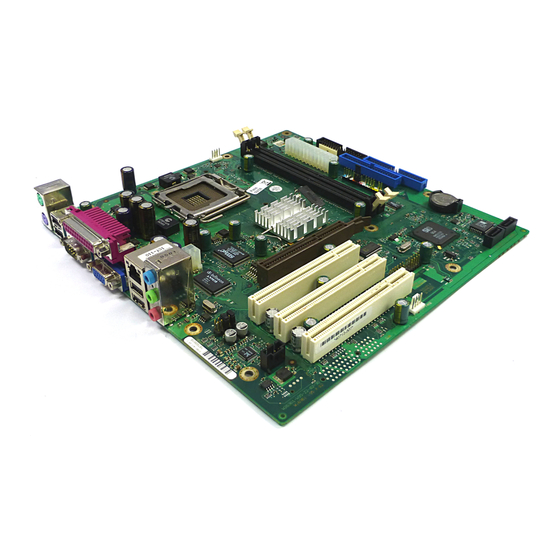
- Page 7 Übersicht/Overview Mainboard D1961 Stromversorgung / Power supply Diskettenlaufwerk / Floppy disk drive IDE-Laufwerke 3/4 / IDE-drives 3/4 Bedienfeld / Front panel IDE-Laufwerke 1/2 / IDE-drives 1/2 Batterie / Battery Serial ATA Serial ATA 10 = USB 11 = Lüfter 2 / Fan 2 (AUX1) 12 = Audio Input / Audio in (optional) 13 = Audio-Bedienfeld / Audio front panel 14 = Zusätzliche Stromversorgung /...
-
Page 9: Table Of Contents
Contents Übersicht/Overview Mainboard D1961 .............. Umschlag / Cover Mainboard D1961..........................1 Notational conventions.......................1 Important notes ..........................2 Information about boards ......................2 List of features...........................3 Special features.........................5 Brief instructions on installing mainboard...................6 Prior to installation ........................6 Interfaces and connectors ......................8 External ports ............................8 LAN port ............................8 Internal ports and connectors ......................9 Hard disk connection .........................9... -
Page 11: Übersicht/Overview Mainboard D1961
Mainboard D1961 Your mainboard is available in different configuration levels. Depending on the configuration chosen, some of the hardware components described may not be available on your mainboard. Additional information Information on the BIOS Setup and additional descriptions of the drivers are contained: ●... -
Page 12: Important Notes
Important notes Important notes With the mainboard installed you must open the system to access the mainboard. How to dismantle and reassemble the system is described in the operating manual accompanying the system. Connecting cables for peripherals must be adequately insulated to avoid interference. Observe the safety notes in the operating manual of your system. -
Page 13: List Of Features
! / ! / ! / - Temperature monitoring CPU/ONB1/ONB2/OFFB ! / - / - / - SmartCard Reader Support (USB / serial) - / - Fujitsu Siemens Computers Keyboard Power Button Support Special onboard features Silent Fan / Silent Fan LT - / ! - Page 14 List of features Internal ports D1961-A DIMM Sockets (DDR 400, SDRAM, PC3200) AGP Slot (2/4/8x, 32 bit, 66 MHz, 1.5 V) PCI slot (32 bit, 33 MHz, 3.3 V, Rev. 2.3) CNR Slot (Type A, AC‘97 only) Serial ATA interface (150 Mbyte/s) / 2 / 2 / 1 ATA interface (100 Mbyte/s) / Floppy interface S/PDIF 5.1 (digital Audio)* OUT / IN...
-
Page 15: Special Features
USB Security is a BIOS function that offers protection against unauthorised access regardless of the operating system used. If USB Security is activated, the system can only be started, if the MemoryBird of Fujitsu Siemens Computers is connected to one of the existing USB-ports. -
Page 16: Brief Instructions On Installing Mainboard
Brief instructions on installing mainboard If you have purchased a separate mainboard, you can install it in your system in accordance with the following brief instructions. The activities described here assume a basic knowledge of PCs and cannot be carried out by a layperson. -
Page 17: Driver Installation
Brief instructions on installing mainboard Installation ► Equip the mainboard with the processor, heat sink and memory modules before installation if possible. Further information can be found in "Replacing the processor" chapter. ► Open the casing as described in the operating manual. -
Page 18: Interfaces And Connectors
Interfaces and connectors The positions of the interfaces and connectors are shown on page "Cover". The components and connectors marked are not necessarily present on the mainboard. External ports The positions of the external ports are shown on page "Cover". PS/2 keyboard port, purple Audio input (Line in), light blue Serial interface, turquoise... -
Page 19: Internal Ports And Connectors
Internal ports and connectors Internal ports and connectors The positions of the internal ports and connectors are shown on the Cover. Additional information on some ports is also provided here. Hard disk connection An ultra ATA/66 or ultra ATA/100 hard disk must be connected with a cable especially designed for the ultra ATA/66 or ultra ATA/100 mode. - Page 20 Internal ports and connectors Using external audio connections Analogue 2-channel audio output With the 2-channel configuration the functions Line-Out, Line-In and MIC are available. 1 = Line-In (blue) 2 = Line-Out (front channels, green) 3 = MIC (red) Analogue 4-channel audio output Line-In is converted into the Rear-Out function with the 4-channel configuration.
-
Page 21: Pin Assignment Of Internal Ports
Pin assignment of internal ports Pin assignment of internal ports The pin assignment of some internal connections is shown in English in the following. Some of the following connectors may be optional! Power On Front panel Power On/Off 1) 2) HD-LED Watch the poling of the LEDs. - Page 22 Pin assignment of internal ports Audio front panel Signal Signal Micro input Analogue GND Micro bias Analogue VCC Right line output Right line return not connected Left line output Left line return If the audio front panel is not used, you must plug jumpers on pin pairs 5/6 and 9/10. USB - dual channel (internal or external via special wire) Signal...
-
Page 23: Floppy Interface
Pin assignment of internal ports Floppy interface Signal Signal Step DIR (low asserted) FDHDIN (low asserted) Step Pulse (low asserted) not connected Write Data (low asserted) not connected Write Enable (low asserted) Index (low asserted) Track 0 (low asserted) Motor A Enable (low asserted) Write Protect (low asserted) - Page 24 Pin assignment of internal ports ATA interface Signal Signal Reset drive (low asserted) Data 7 (high asserted) Data 8 (high asserted) Data 6 (high asserted) Data 9 (high asserted) Data 5 (high asserted) Data 10 (high asserted) Data 4 (high asserted) Data 11 (high asserted) Data 3 (high asserted) Data 12 (high asserted)
- Page 25 Pin assignment of internal ports Power supply BTX (ATX compatible) Signal Signal +3.3 V (P3V3P) +3.3 V (P3V3P) +3.3 V (P3V3P) -12 V (P12VN) +5V (VCC) PS on (low asserted) +5V (VCC) Powergood (high asserted) -5 V (P5VN) +5 V Auxiliary (VCC Aux) +5 V (VCC) +12 V (P12VP) +5 V (VCC)
-
Page 26: Settings With Switches And Jumpers
Settings with switches and jumpers Setting via control-panel plug connector Pin pair A inserted = Skipping system and BIOS Setup password Pin pair B inserted = System BIOS recovery Pin pair C inserted = factory setting Please pay attention on the exact position of the pin pairs! Skipping system and BIOS Setup password - pinpair A Pinpair A enables skipping the system and BIOS Setup password. -
Page 27: Add-On Modules / Upgrading
Celeron with 533 MHz Front Side Bus in the LGA775 design ● A current list of the processors supported by this mainboard is available on the Internet at: www.fujitsu-siemens.com/mainboards. Installing processor with heat sink Never touch the underside of the processor. Even minor soiling such as grease from the skin can impair the processor's operation or destroy the processor. - Page 28 Replacing the processor ► Remove the old processor (2) from the socket. ► Insert the new processor in the socket so that the marking of the processor is aligned with the marking on the socket (a). ► Fold down the frame (1). ►...
- Page 29 Replacing the processor Mounting heat sink Be sure to use heat conducting material between the processor and the heat sink. If a heat conducting pad (rubber-like foil) is already applied to the heat sink, then use it. Otherwise you must apply a very thin layer of heat conducting paste.
-
Page 30: Upgrading Main Memory
128, 256, 512 or 1024 Mbyte for one socket A current list of the memory modules recommended for this mainboard is available on the Internet at: www.fujitsu-siemens.com/mainboards . At least one memory module must be installed. Memory modules with different memory capacities can be combined. -
Page 31: Upgrading Agp Screen Controllers
Upgrading AGP screen controllers Removing a memory module ► Push the clips on the right and left of the memory slot outward (1). ► Pull the memory module out of the memory slot (2). Upgrading AGP screen controllers Technical data The AGP slot supports the modes 4x/8x with 32 bits and 66 MHz. -
Page 32: Pci Bus Interrupts - Selecting Correct Pci Slot
Adding PCI cards PCI bus interrupts - Selecting correct PCI slot To achieve optimum stability, performance and compatibility, avoid the multiple use of ISA IRQs or PCI IRQ Lines (IRQ sharing). Should IRQ sharing be unavoidable, then all involved devices and their drivers must support IRQ sharing. PCI IRQ Lines connect AGP slots, PCI slots and onboard components to the interrupt controller. -
Page 33: Replacing The Lithium Battery
Replacing the lithium battery Replacing the lithium battery In order to permanently save the system information, a lithium battery is installed to provide the CMOS-memory with a current. A corresponding error message notifies the user when the charge is too low or the battery is empty. The lithium battery must then be replaced. Incorrect replacement of the lithium battery may lead to a risk of explosion! The lithium battery may be replaced only with an identical battery or with a type recommended by the manufacturer. -
Page 34: Bios Update
BIOS update BIOS update When should a BIOS update be carried out? Fujitsu Siemens Computers makes new BIOS versions available to ensure compatibility to new operating systems, new software or new hardware. In addition, new BIOS functions can also be integrated. -
Page 35: Bios Recovery - Recovering System Bios
BIOS Recovery - Recovering System BIOS BIOS Recovery - Recovering System BIOS All BIOS settings are reset to the default values. ► Open the casing as described in the operating manual. ► Set the switch for "Restore system BIOS" to ON . ►... -
Page 36: Microcode Update
Safety for processor on Fujitsu Siemens Computers mainboards If the processor uses an old or incorrect microcode, error-free operation cannot be ensured. Fujitsu Siemens Computers has therefore implemented a function on its mainboards that interrupts the booting process if no suitable microcode is available for the installed processor. -
Page 37: Drivers
Drivers Drivers Only when no drivers are installed on your system, or you want to update these, proceed as follows: ► Insert the CD "Drivers & Utilities Collection" into the CD-ROM drive. ► If the CD does not start automatically, run the START.EXE programme in the main directory of the CD. -
Page 38: Annex
Mainboard current requirement You require a Pentium4 power supply nit as per the ATX12V specification for this mainboard. If you do not have a PC from Fujitsu Siemens Computers, make sure that the power supply unit provides the required amperages. -
Page 39: Apm And Acpi System Status, Energy-Saving Modes
APM and ACPI system status, energy-saving modes APM and ACPI system status, energy-saving modes System ACPI Power Power Power Wake-up status Status Status LED I LED II consump time tion Normal On/Off Normal operation Simple Standby Off/On flashing Almost Almost energy-saving like immediatel... -
Page 40: Mainboard Revision And Bios Version
Mainboard Revision and BIOS Version Mainboard Revision and BIOS Version The compatibility, e.g. with new processors, can be independent of the BIOS version or the revision status of the mainboard used. Mainboard Revision The revision status of the mainboard exactly identifies which mainboard you have. It is indicated on a sticker on the edge of the mainboard: D1961-A20 GS 1 05618476... -
Page 41: Error Messages
Available CPUs do not support the same bus frequency - System halted! Memory type mixing detected Non Fujitsu Siemens Memory Module detected - Warranty void There are more than 32 32 RDRAM devices in the system Check whether the system configuration has changed. If necessary, correct the settings. - Page 42 Error messages DMA test failed EISA CMOS not writable Extended RAM Failed at offset: nnnn Extended RAM Failed at address line: nnnn Failing Bits: nnnn Fail-Safe Timer NMI failed Multiple-bit ECC error occurred Memory decreased in size Memory size found by POST differed from EISA CMOS Single-bit ECC error occurred Software NMI failed System memory exceeds the CPU’s caching limit...
- Page 43 Error messages Missing or invalid NVRAM token Switch the device off and on again. If the message is still displayed, please contact your sales outlet or customer service centre. Monitor type does not match CMOS - RUN SETUP Correct the entry for the monitor type in the Main menu of the BIOS Setup . On Board PCI VGA not configured for Bus Master In the BIOS Setup , in the Advanced menu, submenu PCI Configuration , set the Shared PCI Master Assignment entry to VGA .
- Page 44 Error messages System battery is dead - Replace and run SETUP Replace the lithium battery on the mainboard and redo the settings in the BIOS Setup . System Cache Error - Cache disabled Switch the device off and on again. If the message is still displayed, please contact your sales outlet or customer service centre.
-
Page 45: Glossary
Glossary The technical terms and abbreviations given below represent only a selection of the full list of common technical terms and abbreviations. Not all technical terms and abbreviations listed here are valid for the described mainboard. ACPI Advanced Configuration and IPSEC Internet Protocol Security Power Management Interface...
Need help?
Do you have a question about the D1961 and is the answer not in the manual?
Questions and answers