
Subscribe to Our Youtube Channel
Related Manuals for Vaillant VRT 360f


Summary of Contents for Vaillant VRT 360f
- Page 1 For the owner and heating engineer Operating and Installation Manual VRT 360f VRT 360f Room temperature thermostat...
-
Page 2: Table Of Contents
Contents Inhaltsverzeichnis 4.1 Setting the operating modes ..4.2 Setting the current day and Notes on the documentation ..4 time ........... Storage of the documents ....4.3 Setting timer programmes ..Symbols used ........... 4.4 Setting the room temperature ... - Page 3 Installation ....31 9.1 Place of installation ....... 14 Vaillant Service ... . . 46 9.2 Fitting the receiver ......
-
Page 4: Notes On The Documentation
Notes on the documentation Notes on the documentation Symbols used Please observe the safety instructions in The following information is intended to this manual for the installation of the help you throughout the entire appliance. documentation. Other documents apply in combination Danger! with this installation and operation Immediate risk of serious injury... -
Page 5: Safety
Notes on the documentation, safety Safety Note! Useful information and instructions. The room temperature thermostat must be installed by a suitably qualified • Symbol for a necessary task heating engineer, who is responsible for adhering to the existing standards and regulations. -
Page 6: Operating Manual
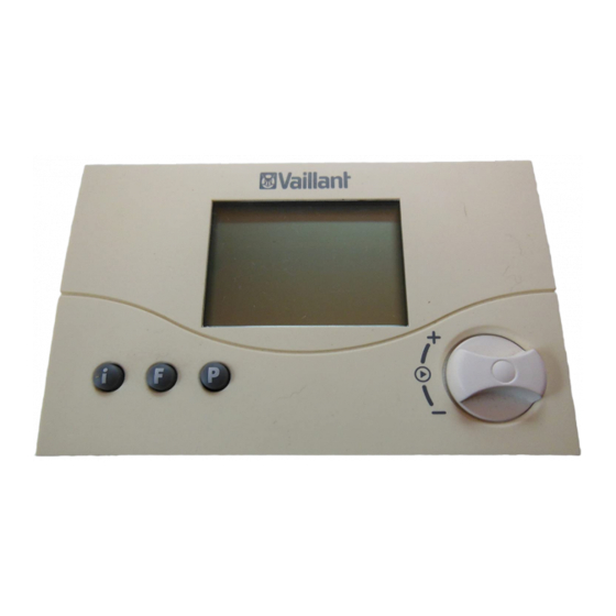
1 Overview of the device Operating manual Overview of the equipment Display 2 Dial (turn and click) Info button F Special functions button P Programming key/installer level Abb. 1.1 Overview of equipment Operating manual VRT 360f... -
Page 7: Overview Of The Display
Overview of the display 2 Overview of the display Installer level and Service/Diagnosis level (Chapter 11.1) 2 Info level (see 4.7) 3 Hot water symbol 4 Circulation pump symbol 5 Heating circuit symbol 6 Time/temperature display 7 Days of the week 8 Actual temperature 9 Operating modes (see 4.1) 10 Special functions (see 4.6) -
Page 8: Description Of The Appliance
The operating principle is based on the Vaillant heating equipment with eBus. three buttons and an dial (Vaillant "turn The connection between the room and click“ operating concept). temperature thermostat and the heating The display normally shows the current unit is by radio link. -
Page 9: Setting The Operating Modes
Operation 4 Setting the operating modes Table 4.1 provides you with an overview of the operating modes you can select. The selected operating mode affects the timer programmes both for heating and for hot water and the circulation pump. • When the room temperature thermostat is in normal display mode. - Page 10 4 Operation Symbol Meaning Heating Hot water Automatic: The operation of the hot water The operation of the heating circuit changes between storage cylinder/circulation the operation modes Heating and Energy Saving pump changes between . The heating circuit symbol is displayed if a heating heating/ON and OFF requirement is detected.
- Page 11 Operation 4 Symbol Meaning Heating Hot water Off: The boiler is not heated up, regardless of The heating circuit is off, provided that the set timer programme. The circulation the frost protection function (if the room pump is switched off. The hot water temperature is below 5°C) and circulation pump symbols are not is not activated.
-
Page 12: Setting The Current Day And Time
4 Operation Setting the current day and • Press the dial. The hours start flashing. time • Turn the dial until you see the current To set the current time and day of the hour. week with the display in normal mode, •... -
Page 13: Setting Timer Programmes
Operation 4 Table 4.2 Default heating, hot water and Setting timer programmes circulation pump programmes The room temperature thermostat is equipped with a basic program (see table 4.2). You can adapt the default programmes to suit your needs. There are six steps to Time Current day Start... - Page 14 4 Operation Display Required steps You can define three time windows for Press the programming each day. button P. The cursor (black When you press the P button the display triangle) marks the value returns to basic mode. which can be changed ( ), The table below illustrates the individual which also flashes.
- Page 15 Operation 4 Display Required steps Display Required steps Press the dial. The cursor Press the dial. The cursor marks the week block marks the start time and the display, which also flashes. hour display flashes. Select a block programme Select the start time by or a single day of the week turning the dial.
-
Page 16: Setting The Room Temperature
4 Operation If necessary, you can switch the room window see Chapter 11.1), the display temperature thermostat from the week shows the currently set room programme to a daily programme. temperature (T-H1, T-H2, T-H3). • With the display in normal mode, press the F button for about 10 Setting the required room temperature seconds. - Page 17 Operation 4 • You can set the required room along with a set value. The set value temperature directly (after about 1 flashes. second) to the desired value by turning • Turn the dial until you see the room the dial. temperature you want for the time The display switches back to normal window H1.
-
Page 18: Setting The Hot Water Temperature
4 Operation • Turn the dial until you see the room The display switches back to normal temperature you want for the time mode after five seconds. window H3. The new room temperature is assigned to all time Setting the hot water windows with H3. -
Page 19: Activating Special Functions
Operation 4 Display Required steps Activating special functions Quick veto You can access the special functions The quick veto function using the F button. You can activate the allows you to adjust the room following functions: temperature for a short time (until the next time window). - Page 20 4 Operation Display Required steps Display Required steps Energy-saving function Party function The energy-saving function lets When you activate the party you lower the heating for an function the heating phase is adjustable period regardless continued beyond the next set- of the set heating programme.
- Page 21 Operation 4 Display Required steps Display Required steps Once-only cylinder filling Holiday function The once-only cylinder filling The holiday function deactivates function allows you to fill the the controller, but not the frost cylinder, regardless of the set protection function. The hot timer programme.
-
Page 22: Info Level
4 Operation Display Required steps - The name of the room temperature ¬ Holiday function Holiday function thermostat (VRT 360f ) If you want to deactivate the - The quick veto room temperature (if function before, just press the F active) button. -
Page 23: Changing The Battery
Operation 4 - The day/month/year (if the calendar is Approx. 4 weeks before the battery is activated) fully discharged BATT appears in the - The timer programmes set for heating multifunction display of the basic display. (every single time window per day) The battery chamber is located on the - The timer programmes set for hot back of the regulator. - Page 24 4 Operation Fig. 4.2 Changing the batteries Fig. 4.1 Releasing the locking hook If the batteries are not changed in time, • The batteries can now be changed the regulator switches over to operating (2x AAA-LR03; Fig. 4.2). Make sure mode "Heating"...
-
Page 25: Manufacturer's Warranty And Liability
Recycling and disposal and liability Both your Valliant room temperature Vaillant warranty thermostat VRT 360f and its packaging We only grant a Vaillant manufacturers consist mainly of recyclable raw warranty if a suitably qualified engineer materials. has installed the system in accordance with Vaillant instructions. - Page 26 6 Recycling and disposal Packaging Please leave the disposal of the transport packaging to the qualified servicing company which installed the appliance. Operating manual VRT 360f...
-
Page 27: Installation Instructions
Vaillant boilers, meets the by a suitably qualified heating engineer. basic requirements of the Council of Check the site of installation before... -
Page 28: Intended Use
Caution! connection with a Vaillant boiler with an Any improper use is forbidden. eBus interface. Installation instructions VRT 360f... -
Page 29: Safety Instructions And Regulati
Safety instructions and regulations 8 Safety instructions and Safety instructions regulations Danger! The unit must be installed by a suitably Risk of fatal electric shock from qualified heating engineer, who is touching live connections. responsible for adhering to the existing Before working on the appliance, standards and regulations. -
Page 30: Regulations
8 Safety instructions and regulations Regulations All wiring must be in accordance with Use standard commercial cables for Building Regulations Part P and BS 7671 wiring. (IEE Wiring Regulations), and must be - Minimum cross-section of the wires: carried out by a suitably qualified per- 0.75 mm son. -
Page 31: Installation
Installation 9 Installation Choose a location where the room temperature thermostat is not affected Place of installation by draughts from doors or windows, or The room temperature thermostat must by heat sources such as radiators, be installed to ensure that it can chimney walls, televisions and direct properly record the room temperature sunlight. - Page 32 9 Installation • Pull the receiver (1) off the wall plinth (2). • Drill two holes (3) of 6 mm diameter (as shown in fig. 9.2) and put in the supplied wall plugs. • Push the connection cable (4) through the cable ducting (5).
-
Page 33: Mounting The Room Temperature Thermostat
Installation 9 Mounting the room temperature thermostat Check the site of installation before fitting the unit with regard to possible radio interference by electrical equipment or building influences which may affect the functioning. If the radio signal route is compromised then an alternative installation site must be chosen. - Page 34 9 Installation • Insert the batteries supplied into the battery compartment at the back of the regulator (Fig. 9.3, Item 4). Make sure that the polarity of the batteries is correct. Connect the connection cable as per Chapter 10. • Push the room temperature thermostat onto the wall plinth until it clicks.
-
Page 35: 10 Electrical Installation
Electrical installation 10 10 Electrical installation 10.1 Connecting the receiver Communication to the boiler takes place The electrical connection may only be using a 2-core bus cable (eBus). All eBus carried out by a suitably qualified connector plugs are designed to allow at heating engineer. -
Page 36: Start-Up
10 Electrical installation, 11 Start-up Start-up Certain system parameters have to be set in order for them to comply with the prevailing conditions. These system Receptor VRT 360f parameters are all together on one operating level and should only be set by the heating engineer. -
Page 37: Installer Level
Start-up 11 The receiver is equipped with two status 11.1 Installer level LEDs. In order to see these you must Press the P button to access the installer remove the cover of the receiver level. housing. The LEDs provide the following •... - Page 38 11 Start-up Display Set by turning the dial Display Set by turning the dial Set-back temperature Anti-legionella function Factory setting: 15 °C 1 = Activate the anti- Setting range: 5 ... 30° C legionnaire's disease programme. Every Wednesday, one hour before the first time window, Set hot water temperature a connected hot water...
- Page 39 Start-up 11 Display Set by turning the dial Display Set by turning the dial Two-point/analogue Control characteristics/ operation route adjustment 2-point/analogue mode For optimum adaptation to change-over. the room size or radiator The room temperature configuration thermostat is set in the Factory setting: 0 factory as a 2-point Setting range: -5 ...
- Page 40 11 Start-up Display Set by turning the dial Display Set by turning the dial Temperature level Day setting Activate the setting for For activation of the different temperatures for calendar each time window. 0 = Temperature level off 1 = Temperature level on Factory setting: 0 Month setting Temperature level time...
-
Page 41: Service/Diagnostics Level
Start-up 11 Display Set by turning the dial 11.2 Service/diagnostics level Access the service/diagnostics level by Temperature level time pressing the P button and the dial. window H2 • Press the P button and the dial (only when temperature simultaneously for approx. 3 seconds. levels are activated) First, a heating request for 50 °C is triggered to test communication with the... - Page 42 11 Start-up Dial Test Test procedure Dial Test Test procedure Press and Heating A heating request of Press Radio route The radio route push P request 50°C is simulated. is tested. Radio button for The burner on the signals are sent to approx.
-
Page 43: Handing Over The Appliance To The Owner
Start-up 11 Restoring the default settings 11.3 Handing over the appliance to • To return the room temperature the owner thermostat to its default settings, The owner of the room temperature press the P button for 15 seconds. As thermostat must be instructed about its soon as the display lights up twice, the functions and how to operate it. -
Page 44: 12 Troubleshooting
12 Troubleshooting 12 Troubleshooting The room temperature thermostat signals the following fault conditions: Fault signal Meaning Troubleshooting RF Err No radio connection to the radio Check the site of installation. receiver on the heating unit BATT low battery condition, replacement Replace the batteries. -
Page 45: Technical Data
Technical data 13 13 Technical data Description Unit Sender Receiver Operating voltage 3V (2xAAA) Maximum permissible ambient temperature °C Battery working life Months approx. 18 Transmission frequency 868,35 868,35 Transmission capacity ≤ 0,4 (readiness) ≤ 12 (readiness) Current consumption Minimum cross-section of the connection lines 0,75 Level of protection IP 20... -
Page 46: 14 Vaillant Service
14 Vaillant Service 14 Vaillant Service Vaillant Service To ensure regular servicing, it is strongly recommended that arrangements are made for a Maintenance Agreement. Please contact Vaillant Service Solutions (0870 6060 777) for further details. Installation instructions VRT 360f... - Page 48 Vaillant Ltd Vaillant House Medway City Estate Trident Close Rochester Kent ME2 4EZ Telephone 01634 292300 Fax 01634 290166 www.vaillant.co.uk info@vaillant.co.uk...
Need help?
Do you have a question about the VRT 360f and is the answer not in the manual?
Questions and answers