
Related Manuals for Rockwell Automation STRATIX 8000 1783-MS06T


Summary of Contents for Rockwell Automation STRATIX 8000 1783-MS06T
- Page 1 Stratix 8000 Ethernet Managed Switches Hardware User Manual 1783-MS06T, 1783-MS10T, Catalog Numbers 1783-MX08T, 1783-MX08F...
-
Page 2: Important User Information
In no event will Rockwell Automation, Inc. be responsible or liable for indirect or consequential damages resulting from the use or application of this equipment. -
Page 3: Preface
Preface This publication describes the physical and performance characteristics of the About This Publication Stratix 8000 Ethernet Managed Switches. In addition, this publication provides the following: • Detailed installation information • How to use the switch • Troubleshooting information This guide does not describe system messages that you might receive or how to configure your switch. -
Page 4: Additional Resources
Product Certifications website, Provides declarations of conformity, http://ab.com certificates, and other certification details. You can view or download publications at http://literature.rockwellautomation.com. To order paper copies of technical documentation, contact your local Rockwell Automation distributor or sales representative. Publication 1783-UM002C-EN-P - April 2009... -
Page 5: Table Of Contents
Table of Contents Preface About This Publication ........5 Who Should Use This Publication . - Page 6 Reset the Switch to Factory Defaults ......58 Connect to the Switch Ports ....... . . 58 Connect to 10/100 Copper Ports .
-
Page 7: Start
Chapter Start This chapter provides a functional overview of the switches and covers these topics. Topic Page About the Switches Power and Relay Connector Console Port Dual-Purpose Uplink Ports 10/100 Ports 100BASE-FX Ports Rear Panel Cabling Status Indicators CompactFlash Memory Card 7Publication 1783-UM002C-EN-P - April 2009... -
Page 8: About The Switches
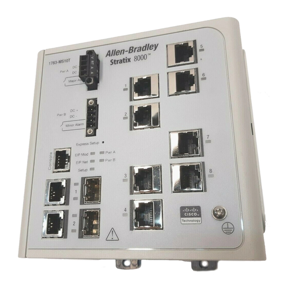
Chapter 1 The Stratix 8000 Ethernet Managed Switches provide a rugged, easy-to-use, About the Switches secure switching infrastructure for harsh environments. You can connect these switches to network devices such as servers, routers, and other switches. In industrial environments you can connect any Ethernet-enabled industrial communication devices including programmable logic controllers (PLCs), human-machine interfaces (HMIs), drives, sensors, and I/O. - Page 9 Chapter 1 1783-MS10T Switch Power and relay connectors Console port Dual-purpose ports 10/100 ports Protective ground connection Publication 1783-UM002C-EN-P - April 2009...
- Page 10 Chapter 1 1783-MX08T Switch Copper Expansion Module (side cover removed) 31827-M 10/100 ports 1783-MX08F Switch Fiber Expansion Module 31828-M 100BASE-FX ports Publication 1783-UM002C-EN-P - April 2009...
-
Page 11: Power And Relay Connector
Chapter 1 You connect the DC power and alarm signals to the switch through two front Power and Relay Connector panel connectors. One connector provides primary DC power (supply A) and the major alarm signal, and a second connector (supply B) provides secondary power and the minor alarm signal. -
Page 12: Console Port
Chapter 1 See the Stratix 8000 Ethernet Managed Switches Software User Manual, publication 1783-UM003A, for more information on alarm configuration.. For more information about the power and relay connector, see Chapter 4, Cable and Connectors. For configuring, monitoring, and managing the switch, you can connect a Console Port switch to a computer through the console port and the supplied RJ45-to-DB-9 adapter cable. -
Page 13: 10/100 Ports
Chapter 1 You can set the 10/100 ports to operate at 10 or 100 Mb/s in full-duplex or 10/100 Ports half-duplex mode. You can also set these ports for speed and duplex autonegotiation in compliance with IEEE 802.3-2002. (The default setting is autonegotiate.) When set for autonegotiation, the port senses the speed and duplex settings of the attached device. -
Page 14: Cabling
Chapter 1 100BASE-TX traffic requires Category 5 cable. 10BASE-T traffic can use Cabling Category 3 or Category 4 cables. When connecting the switch to workstations, servers, and routers, straight-through cables are normally used. However, the automatic medium-dependent interface crossover (auto-MDIX) feature of the switch is enabled by default and will automatically re-configure the ports to use either straight-through or crossover cable type. -
Page 15: Status Indicators
A recoverable minor fault, such as an incorrect configuration, has occurred. Solid red A non-recoverable major fault has occurred. Cycle power. If the problem persists, contact Rockwell Automation Technical Support. Flashing green/red The switch is performing a power-on self-test (POST). EIP Net No power or no IP address. - Page 16 Chapter 1 Indicator State Description Setup Switch is configured as a managed switch. Solid green Switch is in initial setup. Flashing Switch is in one of the following states; gree • initial setup • recovery • initial setup incomplete Solid red Switch failed to start initial setup or recovery because there is no available switch port to which to connect the management station.
-
Page 17: Dual-Purpose Port Status Indicators
Chapter 1 Dual-purpose Port Status Indicators The status indicators on a dual-purpose port, as shown in the following figure, show whether the RJ45 connector or an SFP module is active. The port can be configured as either a 10/100/1000 port through the RJ45 connector or as an SFP module, but not both. The status indicators show which port is being used, and current port activity. -
Page 18: Expansion Module Status Indicators
Chapter 1 Expansion Module Status Indicators State Description No link. Solid green Link present. Flashing green Activity. Port is sending or receiving data. Flashing amber A link blocked by spanning tree is sending or receiving data. Alternating Link fault. Error frames can affect connectivity, and errors such as excessive collisions, CRC errors, and alignment and green/amber jabber errors are monitored for a link-fault indication (RJ45 connection only). -
Page 19: Compactflash Memory Card
Chapter 1 The switch supports a CompactFlash memory card that makes it possible to CompactFlash Memory replace the switch without reconfiguring the switch. The slot for the Card CompactFlash memory card is on the bottom of the switch as shown in the following figure. - Page 20 Chapter 1 Notes: Publication 1783-UM002C-EN-P - April 2009...
-
Page 21: Install The Switch
Chapter Install the Switch This chapter describes how to install your switch, interpret the power-on self-test (POST), and connect the switch to other devices. Read these topics, and perform the procedures in this order. Topic Page Installation Guidelines Before You Begin Verify Package Contents Add Modules to the Switch Install the Switch... - Page 22 Chapter 2 This equipment is intended to be grounded. Ensure that the host is connected to earth ground during WARNING normal use. Before working on equipment that is connected to power lines, remove jewelry (including rings, necklaces, and watches). Metal objects will heat up when connected to power and ground and can cause serious burns or weld the metal object to the terminals.
- Page 23 Chapter 2 This equipment is intended to be grounded to comply with emission and immunity requirements. Ensure WARNING that the switch functional ground lug is connected to earth ground during normal use. When used in a Class I, Division 2, hazardous location, this equipment must be mounted in a suitable enclosure with proper wiring method, for all power, input and output wiring, that complies with the governing electrical codes and in accordance with the authority having jurisdiction over Class I, Division 2 installations.
-
Page 24: Installation Guidelines
Chapter 2 When determining where to place the switch, observe these guidelines. Installation Guidelines Environment and Enclosure Guidelines Review these environmental guidelines before installation. • This equipment is intended for use in a Pollution Degree 2 industrial environment, in overvoltage Category II applications (as defined in IEC publication 60664-1), at altitudes up to 3 km (9842 ft) without derating. -
Page 25: Place The Switch
Chapter 2 Place the Switch When determining where to place the switch, observe these guidelines • Before attaching the switch to the network, first verify that the switch is operational by powering it on and running POST. Follow the procedures in the Verify Switch Operation section on page •... -
Page 26: Verify Package Contents
Chapter 2 Carefully remove the contents from the shipping container, and check each Verify Package Contents item for damage. If any item is missing or damaged, contact your Rockwell Automation representative for assistance. The switch is shipped with these items. •... - Page 27 Chapter 2 The following table lists some port combinations using switch and expansion modules. Switch and Expansion Module Port Combinations Port Type Switch and Expansion Modules Combination 100FE 100FX (copper) (fiber optic) one 1783-MS06T switch one 1783-MS10T switch one 1783-MS06T switch one 1783-MX08F expansion module one 1783-MS06T switch one 1783-MX08T expansion module...
- Page 28 Chapter 2 1783-MS06T switch with 1783-MX08T and 1783-MX08F expansion modules (12 copper and 8 fiber optic ports) 1783-MS06T switch with one 1783-MX08F expansion module (4 copper and 8 fiber optic ports) 1783-MS06T switch with one 1783-MX08T expansion modules (12 copper ports) 1783-MS06T switch with two 1783-MX08T expansion modules (20 copper ports) Publication 1783-UM002C-EN-P - April 2009...
-
Page 29: Install The Switch
Chapter 2 Perform these procedures to install the switch. Install the Switch If you connect or disconnect the communication cable with ATTENTION power applied to this module or any device on the network, an electrical arc can occur. This could cause an explosion in hazardous location installations. - Page 30 Chapter 2 You can install one or two expansion modules, limited to these four combinations: • ne copper expansion module (1783-MX08T) • one fiber expansion module (1783-MX08F) • two copper expansion modules • one copper and one fiber expansion module Only one 1783-MX08F expansion module is allowed per switch.
- Page 31 Chapter 2 If necessary, use a screwdriver to pry open the side panel. 31779-M 2. Remove the protective EMI-connector cover from the side panel. 31787-M 3. Push the upper module latches up and the lower module latches down. Then slide the switch and module together. 31780-M The expansion module is shown with the side panel removed.
-
Page 32: Mount The Switch
Chapter 2 4. Push the upper and lower module latches in to secure the module to the switch. 31781-M 5. If you are installing a second module, repeat steps 1...4, but secure the second module to the right side of the first module. You cannot install an expansion module to the right of IMPORTANT 1783-MX08F fiber expansion module. - Page 33 Chapter 2 1. Insert a sharp tool such as a screwdriver in the space next to the tab, push gently to release the catch, then turn the screwdriver to push the tab out. 31776-M 2. If you are using a heavy-duty 35 mm x 15 mm (1.38 in. x 0.59 in.) DIN rail, rotate all feet to the extended positions.
- Page 34 Chapter 2 4. Push the DIN rail latches in after the switch is over the DIN rail to secure the switch to the rail. 5. Ground the switch. Refer to Ground the Switch on page 6. Wire the switch. Refer to Wire the DC Power Source on page Publication 1783-UM002C-EN-P - April 2009...
- Page 35 Chapter 2 Install the Switch on a Wall or Panel The switch can be installed on a wall or a panel. To attach the switch to a wall or a panel, follow these steps. If you are installing expansion modules, attach the expansion IMPORTANT modules to the switch before mounting the switch.
- Page 36 Chapter 2 1. Position the rear panel of the switch against the wall or a panel in the desired location, as shown in this figure. o j a i h T t i n i m t h g a h e v r o c .
-
Page 37: Install The Sfp Module (Optional)
Chapter 2 Install the SFP Module (optional) SFP modules are static sensitive devices. Always use an ESD ATTENTION wrist strap or similar individual grounding device when handling SFP modules. Using an SFP module other than those provided by Rockwell IMPORTANT Automation will disable the switch port. -
Page 38: Ground The Switch
Chapter 2 Ground the Switch Follow these steps to connect the switch to a protective ground. For proper grounding, you must always connect the power ATTENTION supply functional-ground screw when connecting the power supply. You must provide an acceptable grounding path for each device in your application. - Page 39 Chapter 2 5. Using a crimping tool, crimp the ring terminal to the wire. 31790-M 6. Slide the ground screw through the ring terminal. 7. Insert the ground screw into the ground-screw opening on the front panel. 31791-M 8. Using a ratcheting torque screwdriver, tighten the ground screw and ring terminal lug to the switch front panel to 0.96 N•m (8.5 lb•in).
-
Page 40: Wire The Dc Power Source
Chapter 2 Wire the DC Power Source Before performing any of the following procedures, make sure WARNING that power is removed from the DC circuit or the area is nonhazardous before proceeding. To comply with the CE Low Voltage Directive (LVD), this ATTENTION equipment must be powered from a source compliant with the safety extra low voltage (SELV) or protected extra low voltage... - Page 41 Chapter 2 Do not strip more than 6.8 mm (0.27 in.) of insulation from the wire. Stripping more than the recommended amount of wire can leave exposed wire from the connector after installation. 6.8 mm (0.27 in.) 31784-M 5. Insert the exposed part of the positive wire into the connection labeled V and the exposed part of the return wire into the connection labeled Make sure that you cannot see any wire lead.
-
Page 42: Attach The Power And Relay Connector
Chapter 2 Attach the Power and Relay Connector Follow these steps to connect the DC power and relay connector to the switch:. The input voltage source of the alarm circuits must be an ATTENTION isolated source and limited to less than or equal to 30V DC, 1 A. 1. - Page 43 Chapter 2 3. If a second power source is required (for redundancy), insert a second power and relay connector into the Pwr B receptacle on the switch front panel 31788-M If multiple power sources are used, do not exceed the specified ATTENTION isolation voltage.
-
Page 44: Wire The External Alarms (Optional)
Chapter 2 Wire the External Alarms (Optional) This procedure is optional. The alarm relays on the switch are normally open. To connect an external alarm device to the relays, you must connect two relay contact wires to complete an electrical circuit. Because each external alarm device requires two connections to a relay, the switch supports a maximum of two external alarm devices. - Page 45 Chapter 2 External device, relay wire A connection 1 External device, relay wire A connection 2 4. Use a flat-head screwdriver to torque the power and relay connector captive screw (above the installed wire leads) to 0.23 N•m (2.0 lb•in.). 31785-M 5.
- Page 46 Chapter 2 Power source A positive connection Power source B positive connection Power source A return connection Power source B return connection External device 1, relay wire major alarm External device 2, relay wire minor alarm connection connection External device 1, relay wire major alarm External device 2, relay wire minor alarm connection connection...
-
Page 47: Install Or Remove The Compactflash Card
Chapter 2 Follow this procedure to install or remove the CompactFlash card. Install or Remove the CompactFlash Card When you insert or remove the CompactFlash Card while power WARNING is on, an electrical arc can occur. This could cause an explosion in hazardous location installations. -
Page 48: Set Up The Switch Initially With Express Setup
Chapter 2 When you first set up the switch, use Express Setup to enter the initial IP Set Up the Switch Initially address. Doing this enables the switch to be used as a managed switch. You with Express Setup can then access the switch through the IP address for additional configuration. You need this equipment to set up the switch: •... - Page 49 Chapter 2 If the switch fails POST, the EIP Mod status indicator turns red. EIP Mod Status Indicator Setup Status Indicator 31793-M 4. Press and release the Express Setup button. Wait for a few seconds until the status indicator on one of the unconnected switch ports flashes green.
- Page 50 Chapter 2 6. While the Setup status indicator flashes green, start an Internet browser session on the personal computer. The switch prompts you for the default switch username and password. 7. Leave the username field blank. 8. Enter the default switch password, switch. The Express Setup dialog box automatically appears.
- Page 51 Chapter 2 10. Enter the network settings. All entries must be English letters and Arabic numbers. In this field Do this Management Interface (VLAN) The default is VLAN 1. Do not change from the default setting unless instructed to do so by your IT department.
- Page 52 Chapter 2 For more information about the optional settings, from the toolbar, click Help. 1. Click Submit to save the information that you entered and to finish the basic configuration. • Once you click Submit, the switch initializes its configuration for typical industrial EtherNet/IP applications.
-
Page 53: Configure And Manage The Switch
Chapter 2 After you complete Express Setup, you can further configure and manage the Configure and Manage the switch by using one of these options: Switch • Device Manager web interface (supplied with the switch) • RSLogix 5000 software, version 16 or later •... -
Page 54: Use Rslogix 5000 Software
Chapter 2 Use RSLogix 5000 Software The RSLogix 5000 software add-on profile (AOP) lets you set up an I/O (CIP) connection to the switch, and configure and monitor the switch. Follow this procedure to add the switch to the controller’s I/O tree. These steps are required before you can go online to configure IMPORTANT and monitor the switch. - Page 55 If you do not see the switch on the list, you may need to obtain the AOP from the Rockwell Automation support website. 1. Go to http://www.rockwellautomation.com/support/. 2. Click Downloads/RSLogix 5000 I/O Modules Add-on Profiles.
-
Page 56: Download Cisco Network Assistant
Chapter 2 1. Click OK. The switch is added to the project. 2. Go online with the switch by choosing Communications online. You can now configure and monitor the switch using the switch AOP. For more information on using the switch AOP, refer to the Stratix 8000 Managed Ethernet Switch Software User manual, publication 1783-UM003. -
Page 57: Use The Command-Line Interface
Chapter 2 Use the Command-Line Interface You can manage the switch from the command-line interface (CLI) by connecting your personal computer directly to the switch console port or through the network by using Telnet. This procedure explains how to access the CLI through the console port. -
Page 58: Reset The Switch To Factory Defaults
Chapter 2 Follow this procedure if you need to restore the switch to its factory default settings. Reset the Switch to Factory Defaults This procedure resets the switch to its original factory settings. Any configuration changes you may have made will be lost. 1. -
Page 59: Connect To 10/100 Copper Ports
Chapter 2 Connect to 10/100 Copper Ports 1. Insert a straight-through, twisted four-pair, Category 5e or better cable with an RJ45 connector into the port. To 10/100 ports 31795-M 2. Insert the other cable end into an RJ45 connector on the other device. Connect to Dual-purpose Uplink (10/100/1000 and SFP Fiber) Ports The switches have two dual-purpose uplink ports. - Page 60 Chapter 2 Connect to SFP Fiber Ports Follow this procedure if you have installed an optional SFP module. Class 1 laser product. Laser radiation is present when the ATTENTION system is open and interlocks bypassed. Only trained and qualified personnel should be allowed to install, replace, or service this equipment.
-
Page 61: Connect To 100Basefx Ports
Chapter 2 Connect to 100BaseFX Ports Class 1 laser product. Laser radiation is present when the ATTENTION system is open and interlocks bypassed. Only trained and qualified personnel should be allowed to install, replace, or service this equipment. 1. Insert a fiber optic cable with an LC connector into the 100BASE-FX port of the 1783-MX08F expansion module. -
Page 62: Verify Switch Operation
Chapter 2 Before installing the switch in its final location, you should power on the Verify Switch Operation switch and verify that the switch passes the power-on self-test (POST). These sections describe the steps required to connect a personal computer or terminal to the switch console port, to power on the switch, and to observe POST results. -
Page 63: Run A Power-On Self-Test (Post)
Chapter 2 When the switch powers on, it automatically initiates a POST. The POST runs Run a Power-on Self-test a series of tests that verify that the switch functions properly and assures that it (POST) is ready to install. To test the switch, follow these steps. 1. -
Page 64: Disconnect Power
(TX) and receive (RX). SFP modules can be installed and removed under power. Use only Rockwell Automation SFP modules on the switch. Each SFP module has an internal serial EEPROM that is encoded with security information. This encoding identifies and validates that the module meets the requirements for the switch. -
Page 65: Remove Sfp Modules From Sfp Module Slots
Chapter 2 To insert an SFP module into the SFP module slot, follow these steps: 1. Attach an electrostatic discharge (ESD) preventive wrist strap to your wrist and to a bare metal surface on the chassis. 2. Find the send (TX) and receive (RX) markings that identify the correct side of the SFP module. - Page 66 Chapter 2 4. Unlock and remove the SFP module, as shown the following figure. Bale Clasp Latch 5. If the module has a bale-clasp latch, pull the bale out and down to eject the module. If the bale-clasp latch is obstructed and you cannot use your index finger to open it, use a small, flat-blade screwdriver or other long, narrow instrument to open the bale-clasp latch.
-
Page 67: Connect To Sfp Modules
Chapter 2 This section describes how to connect to a fiber-optic SFP port. To connect to Connect to SFP Modules an RJ45 Gigabit Ethernet port instead of a fiber-optic port, see the Connect to the Switch Ports section on page Follow these steps to connect a fiber-optic cable to an SFP module: Do not remove the rubber plugs from the SFP module port or the WARNING... - Page 68 Chapter 2 4. Observe the port status indicator. • The status indicator turns green when the switch and the target device have an established link. • The status indicator turns amber while the SFP module discovers the network topology and searches for loops. This process takes about 30 seconds, then the port status indicator turns green.
-
Page 69: Troubleshoot The Switch
Chapter Troubleshoot the Switch This chapter provides these topics for troubleshooting the switch. Topic Page Obtain Troubleshooting Information Verify Switch POST Results Verify Switch Status Indicators Verify Switch Connections Verify Switch Performance Obtain Configuration Information Obtain Troubleshooting The status indicators on the front panel provide troubleshooting information about the switch. -
Page 70: View Post Results With A Terminal
Chapter 3 View POST Results With a Terminal If you have a terminal connected to the console port, you can also view POST status and test results on the terminal. If the terminal displays garbled characters, you might need to reset the terminal-emulation software to 9600 bits per second. -
Page 71: Ethernet And Fiber Cables
Chapter 3 This situation is likely when the port has many packet errors or the port constantly loses and regains the link. You should: • Swap the copper or fiber-optic cable with a known, good cable. • Look for broken, bent, or missing pins on cable connectors. •... -
Page 72: Link Status
Disconnect the cable, and then reconnect it. Transceiver Issues Use only Rockwell Automation SFP modules on the switch. Each SFP module has an internal serial EEPROM that is encoded with security information. This encoding identifies and validates that the module meets the requirements for the switch. -
Page 73: Port And Interface Settings
Chapter 3 Port and Interface Settings A cause of port connectivity failure can be a disabled port. Verify that the port or interface is not disabled or powered down for some reason. If a port or interface is manually shut down on one side of the link or the other side, the link does not come up until you re-enable the port. -
Page 74: Autonegotiation And Network Interface Cards (Nics)
See Chapter 4, Cable and Connectors cabling guidelines. If you contact Rockwell Automation Technical Support, you may be asked to Obtain Configuration provide configuration information for your switch. You can obtain this Information information from the Device Manager web interface online help. -
Page 75: Cable And Connectors
Chapter Cable and Connectors This appendix describes the switch ports and the cables and adapters that you use to connect the switch to other devices. The 10/100 and 10/100/1000 Ethernet ports on switches use standard RJ45 10/100 and 10/100/1000 connectors and Ethernet pinouts with internal crossovers. Ports The auto-MDIX feature is enabled by default. -
Page 76: Connect To 10Base-T- And 100Base-Tx-Compatible Devices
Chapter 4 Connect to 10BASE-T- and 100BASE-TX-Compatible Devices When connecting the ports to 10BASE-T- and 100BASE-TX-compatible devices, such as servers, workstations, and routers, you can use a two or four twisted-pair, straight-through cable wired for 10BASE-T and 100BASE-TX. To identify a crossover cable, compare the two modular ends of the cable. Hold the cable ends side-by-side, with the tab at the back. - Page 77 Chapter 4 Use a straight-through cable to connect two ports only when one port is designated with an X. Use a crossover cable to connect two ports when both ports are designated with an X or when both ports do not have an X. You can use Category 3, 4, or 5 cabling when connecting to 10BASE-T-compatible devices.
-
Page 78: 100Base-Fx Ports
Chapter 4 The 100BASE-FX ports use the following: 100BASE-FX Ports • LC connectors, as shown in the following figure. • 50/125- or 62.5/125-micron multimode fiber-optic cables Fiber-optic SFP Module LC Connector Invisible laser radiation may be emitted from disconnected ATTENTION fibers or connectors. -
Page 79: Dual-Purpose Ports
Chapter 4 The Ethernet port on a dual-purpose port uses standard RJ45 connectors. The Dual-purpose Ports following figure shows the pinouts. Ethernet Port RJ45 Connector Label 4 5 6 7 8 TP0+ TP0- TP1+ TP2+ TP2- TP1- TP3+ TP3- The SFP module slot on a dual-purpose port uses SFP modules for fiber-optic ports. -
Page 80: Cable And Adapter Specifications
Chapter 4 These sections describe the cables and adapters used with the switches. Cable and Adapter Specifications SFP Module Cable Specifications The following lists the cable specifications for the rugged fiber-optic SFP module connections. Each port must match the wave-length specifications on the other end of the cable, and for reliable communications, the cable must not exceed the rated maximum cable length. - Page 81 Chapter 4 The RJ45-to-DB-25 female DTE adapter is not supplied with the switch. Switch Console RJ45-to-DB-25 Console Port (DTE) Terminal Adapter Device Signal DB-25 Pin Signal Publication 1783-UM002C-EN-P - April 2009...
- Page 82 Chapter 4 Notes: Publication 1783-UM002C-EN-P - April 2009...
- Page 83 ___No, there is no need to contact me ___Yes, please call me ___Yes, please email me at _______________________ ___Yes, please contact me via _____________________ Return this form to: Rockwell Automation Technical Communications, 1 Allen-Bradley Dr., Mayfield Hts., OH 44124-9705 Fax: 440-646-3525 Email: RADocumentComments@ra.rockwell.com Publication CIG-CO521D-EN-P- July 2007...
- Page 84 PLEASE FASTEN HERE (DO NOT STAPLE) Other Comments PLEASE FOLD HERE NO POSTAGE NECESSARY IF MAILED IN THE UNITED STATES BUSINESS REPLY MAIL FIRST-CLASS MAIL PERMIT NO. 18235 CLEVELAND OH POSTAGE WILL BE PAID BY THE ADDRESSEE 1 ALLEN-BRADLEY DR MAYFIELD HEIGHTS OH 44124-9705...
- Page 85 Index Numerics connectors and cables 10/100/1000 76 10/100 ports console 79 cable lengths 25 dual-purpose 79 described 13 SC connectors 78 10/100/1000 ports 17 SFP module ports 78 cable lengths 25 console port described 12 connecting to 62 100BASE-FX ports default characteristics 62 cable lengths 25 described 12...
- Page 86 running at power on 69 status indicators 69 industrial environment warning 23 power installation 29 connecting to guidelines 24 power and relay connector 11 package contents 26 power and relay connector 11 POST 63 described 11 pre-installation information and power connection guidelines 25 power and relay connector 11 required clearance 25...
- Page 87 terminal-emulation software 62 verifying package contents 26 troubleshooting verifying switch operation 62 bad or damaged cable 70 connection problems 70 diagnosing problems 69 warnings Ethernet and fiber cables 71 functional ground lug 22 link status 72 hazardous locations port and interface settings 73 console cable 12 POST 69 industrial environment 23...
- Page 88 Publication 1783-UM002C-EN-P - April 2009...
- Page 92 New Product Satisfaction Return Rockwell Automation tests all of its products to ensure that they are fully operational when shipped from the manufacturing facility. However, if your product is not functioning and needs to be returned, follow these procedures.
Need help?
Do you have a question about the STRATIX 8000 1783-MS06T and is the answer not in the manual?
Questions and answers