Table of Contents
Advertisement
Advertisement
Table of Contents

Related Manuals for Caple CR 9100


Summary of Contents for Caple CR 9100
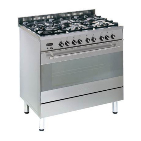
- Page 1 Gas Cooker with Multifunction oven CR 9100 Model: Instruction Manual...
- Page 2 Thank you for buying your new CAPLE cooker. To ensure that you get the best results from your new CAPLE cooker, we strongly suggest that you read this instruc- tion manual thoroughly before use. This manual contains installation advice, cleaning tips and a cooking guide, as well as other important facts about your CAPLE cooker.
-
Page 3: Safety Reminders
The Grill and Top oven element ommend that any servicing or repairs are carried out only by an authorised CAPLE are exposed, so take great care when SERVICE ENGINEER. placing food in the oven or removing it. -
Page 4: Electrical Requirements
Electrical Requirements WARNING! ELECTRICITY CAN BE EXTREMELY DANGEROUS. THIS APPLIANCE MUST BE EARTHED. For your safety please read the following information: This appliance must be installed by a qualified technician according with the current local regulations and in compliance with the manufacturer instructions. The appliance must be connected to the electrical network verifying above all that the voltage corresponds to the value indicated on the specifications plate and that the cables section of the electrical plant can bear the load which is also indicated on the plate. -
Page 5: Feeder Cable Section
1 - Electrical Installation - Wall box connection This appliance must be connected to a DOUBLE POLE SWITCHED double pole isolating switch (fig. 1.1) and FUSED SPUR OUTLET to the terminal block in the cooker (figs. 1.2 & 1.3) using the following guide: 1) The wire which is coloured brown must be connected to the terminal marked L (Live), or coloured Red. - Page 6 FOR THE INSTALLER 2 - Location The cooker must be installed by a qualified technician and in compliance with local safety standards. This cookers has class “2/1” overheating protection so that it can be installed next to a cabinet. The furniture walls adjacent to the cooker must be made of material resistant to heat. The veneered syntetical material and the glue used must be resistant to a temperature of 120°C in order to avoid ungluing or deformations.
-
Page 7: Assembling The Backguard
ASSEMBLING THE BACKGUARD Before installing the cooker, assemble the backguard “C” (fig. 2.2). 1. The backguard “C” can be found packed at the rear of the cooker. 2. Before assembling remove any protective film/adhesive tape. 3. Remove the two spacers “A” and the screw “B” from the rear of the cooktop. 4. -
Page 8: Levelling The Cooker
WARNING When raising cooker to upright posi- tion always ensure two people carry out this manoeuvre to prevent dam- age to the adjustable feet (fig. 2.4). WARNING Be carefull: do not lift the cooker by the door handle when raising to the upright position (fig. - Page 9 Provison for ventilation The room containing the cooker should have an air supply in accordance with BS.5540: Part 2: 1989. All rooms require an openable window or equivalent while some rooms require a per- manent vent in addition to the openable window. The cooker should not be installed in a bed-sitting room, of volume less than 21 m Where a DOMESTIC COOKER is installed in a room or internal space, that room or internal space shall be provided with a permanent opening which communicates directly...
-
Page 10: Gas Connection
3 - Gas connection GAS CONNECTION GAS INSTALLATION The installation of the cooker to Natural IMPORTANT NOTE Gas or LP Gas must be carried out by This appliance is supplied for use on a qualified gas engineer. Installers shall NATURAL GAS only and cannot be used take due account of the provisions of the on any other gas without modification. - Page 11 GAS CONNECTION The gas supply must be connected to the gas inlet which is located at the left or the right hand rear of the appliance (fig. 3.1). The pipe does not cross the cooker. When screwing the connecting tube operate with two spanners (fig.
-
Page 12: Conversion To Lpg
Conversion to LPG Conversion procedure Injectors replacement Select the injectors to be replaced according to the “Table for the choice of the injectors” (page 13). To replace the injectors proceed as fol- lows: - Remove pan supports and burners from the cooktop. - Using a wrench, substitute the nozzle injectors “J”... -
Page 13: Lubrication Of The Gas Taps
TABLE FOR THE CHOICE OF THE INJECTORS Cat: 2H3+ G 30 - 28-30 mbar G 20 Reduced Nominal BURNERS G 31 - 37 mbar 20 mbar Power Power By-pass By-pass Ø injector Ø injector [kW] [kW] [1/100 mm] [1/100 mm] [1/100 mm] [1/100 mm] 1,00... -
Page 14: Features And Technical Data
4 - Features and Technical Data Fig. 4.1 Fig. 4.2 Control panel - Cooking hob - (Fig. 4.2) (Fig. 4.1) 1. Auxiliary burner (A) 1,00 kW 1. Electronic clock/end cooking timer 2. Triple-ring burner (TC) 3,50 kW 2. Multifunction oven switch knob 3. -
Page 15: How To Use The Hob Burners
How To Use the Hob Burners Hob burners Each hob burner is controlled by a separate gas tap operated by a control knob (fig. 4.3) which has 3 positions marked on the knob, these are: – Symbol : tap closed (burner off) –... - Page 16 Choice of burner The burner must be chosen according to the diameter of the pans and energy required. Burners Pan diameter Auxiliary 12 ÷ 14 cm Semi-rapid 16 ÷ 24 cm Rapid 24 ÷ 24 cm Triple-ring 26 ÷ 28 cm do not use pans with concave or convex bases Fig.
- Page 17 CORRECT USE OF TRIPLE-RING BURNER The flat-bottomed pans are to be placed directly onto the pan-support. When using a WOK you need to place the supplied stand in the burner to avoid any faulty operation of the triple-ring burner. CORRECT WRONG Fig.
- Page 18 5 - Electronic clock / end cooking timer COOKING WITH AUTOMATIC The electronic programmer is a device with the following functions: SWITCH-OFF – 24 hours clock with illuminated The aim of this function is to display automatically stop the cooking after a pre –...
-
Page 19: How To Use The Multi-Function Oven
6 - How To Use the Multi-function oven OPERATING PRINCIPLES Attention: the oven door becomes very hot during operation. Heating and cooking in the MULTI- Keep children away. FUNCTION oven are obtained in the fol- lowing ways: As its name indicates, this is an oven that presents particular features from an a. -
Page 20: Thermostat Knob
THERMOSTAT KNOB OVEN LIGHT To turn on the heating elements of the oven, set the switch knob on the desired By turning the knob onto this setting program and the thermostat knob onto (see picture aside) we light the oven the desired temperature. - Page 21 GRILLING HOT AIR COOKING The infra-red heating element is switched The circular element and the fan are on. on. The heat is diffused by radiation. heat diffused forced Set the thermostat knob to between 50° convection and the temperature must be regulated between 50°...
-
Page 22: Cooking Advice
COOKING ADVICE MAINTAINING TEMPERATURE AFTER COOKING OR SLOWLY HEATING FOODS STERILIZATION Sterilization of foods to be conserved, in full and hermetically sealed jars, is done The upper element and the circular ele- ment connected in series, are switched on; in the following way: also the fan is on. -
Page 23: Use Of The Grill
SIMULTANEOUS COOKING OF DIF- GRILLING AND “AU GRATIN” FERENT FOODS Set the switch to position Set the thermostat to position 175 °C and The MULTI-FUNCTION oven set on after having preheated the oven, simply position gives simultaneous place the food on the shelf. heterogeneous cooking of different foods. - Page 24 ROTISSERIE This is used for spit roasting under the grill and comprises: – an electric motor fitted to the rear of the oven – a stainless steel skewer provided with slide-out heatless handgrip and two sets of adjustable forks – a skewer support to be fitted in the mid- dle runner.
- Page 25 Recommended cooking temperature Food °C °F Shelf Cooking Mark Position Time (approx) CAKES Victoria sandwich 2 or 3 20-25 mins Small cakes/buns 1 and 2 15-20 mins Maidera cake 2 or 3 20 mins 3 /4 Fruit cake hours 1 /2 Rich fruit cake 3 or 4 hours...
-
Page 26: Cleaning And Maintenance
7 - Cleaning and Maintenance GENERAL ADVICE – When the appliance is not being used, it is advisable to keep the gas tap closed. – Every now and then check to make sure that the flexible tube that connects the gas line or the gas cylinder to the appliance is in perfect condition and eventually substitute it if it shows signs of wearing or damage. -
Page 27: Stainless Steel Surfaces
CLEANING All the enamelled parts must be cleaned with a sponge and soapy water or other non- abrasive products. Dry preferably with a soft cloth. Acidic substances like lemon juice, tomato sauce, vinegar etc. can damage the enamel if left too long. STAINLESS STEEL SURFACES The stainless steel front panels on this cooker (facia, oven door, drawer or storage compartment) are protected by a finger-print proof lacquer. - Page 28 Gas tap If a tap becomes stiff, do not force; contact your local Service Centre. Flexible tube From time to time, check the flexible tube connecting the gas supply to the cooker. It must be always in perfect condition; in case of damage arrange for it to be replaced by a C.O.R.G.I.
- Page 29 Fig. 7.2 Fig. 7.3 Triple ring burner The triple ring burner must be correctly positioned (see figs. 7.2-7.3); the burner rib must be enter in their logement as shown by the arrow. The burner correctly positioned must not rotate (fig. 7.3). Then position the cap A and the ring B (fig.
-
Page 30: Storage Compartment
Fig. 7.6 Fig. 7.7 OVEN DOOR STORAGE COMPARTMENT The storage compartment is accessible The internal glass panel can be easily through the pivoting pane l(fig. 7.7). removed for cleaning by unscrewing the 4 retaining screws (Fig. 7.6) Do not store flammable material in the oven or in the dishwarmer compartment. - Page 31 ASSEMBLY AND DISMANTLING OF THE SIDE RUNNER FRAMES – Fit the side runner frames into the holes on the side walls inside the oven (Fig. 7.8). – Slide the tray and rack into the run- ners (Fig. 7.9). – To dismantle, operate in reverse order.
-
Page 32: Removing The Oven Door
REMOVING THE OVEN DOOR Fig. 7.12A The oven door can easily be removed as follows: – Open the door to the full extent (fig. 7.12A). – Attach the retaining rings to the hooks on the left and right hinges (fig. 7.12B). -
Page 33: Helpful Advice
NOTE: Oven bulb replacement is not covered by your guarantee. Other bulbs cannot be changed by yourself and should be replaced by an authorised CAPLE Service Engineer. Bulbs other than the oven bulb are covered by the guarantee. - Page 34 2. Make sure the timer control is set to the manual position, and that the oven has not been set inadvertently for an automatic or timed programme. If you are in any doubt about carrying out these checks, call the CAPLE Helpline on 0870 241 1142.
- Page 36 YOUR GUARANTEE CAPLE guarantees all parts of this product for one year from the date of pur- chase. During that time, should it become necessary CAPLE engineers will replace or repair all defective parts free of charge, except for parts subject to fair wear and tear, such as lightbulbs.
Need help?
Do you have a question about the CR 9100 and is the answer not in the manual?
Questions and answers