Table of Contents
Advertisement
Advertisement
Table of Contents

Related Manuals for Asus P5E64 WS Pro


Summary of Contents for Asus P5E64 WS Pro
- Page 1 P5E64 WS Evolution...
- Page 2 Product warranty or service will not be extended if: (1) the product is repaired, modified or altered, unless such repair, modification of alteration is authorized in writing by ASUS; or (2) the serial number of the product is defaced or missing.
-
Page 3: Table Of Contents
Product highlights ............1-2 1.3.2 ASUS special features ........... 1-4 1.3.3 ASUS stylish features ............. 1-7 1.3.4 ASUS intelligent overclocking features ......1-7 Chapter 2: Hardware information Before you proceed ..............2-1 Motherboard overview ..............2-2 2.2.1 Placement direction ............2-2 2.2.2... -
Page 4: Contents
4.1.1 ASUS Update utility ............4-1 4.1.2 Creating a bootable floppy disk ........4-4 4.1.3 ASUS EZ Flash 2 utility ........... 4-5 4.1.4 AFUDOS utility ..............4-6 4.1.5 ASUS CrashFree BIOS 3 utility ........4-8 BIOS setup program ..............4-9 4.2.1... - Page 5 Contents Main menu .................. 4-12 4.3.1 System Time ..............4-12 4.3.2 System Date ..............4-12 4.3.3 Legacy Diskette A ............4-12 4.3.4 Language ..............4-12 4.3.5 SATA 1~6 ..............4-13 4.3.6 SATA Configuration ............4-14 4.3.7 AHCI Configuration ............4-15 4.3.8 System Information ............
- Page 6 Boot Device Priority ............4-35 4.7.2 Boot Settings Configuration .......... 4-36 4.7.3 Security ................. 4-37 Tools menu ................. 4-39 4.8.1 ASUS EZ Flash 2 ............4-39 4.8.2 ASUS O.C. Profile ............4-40 4.8.3 Ai Net 2 ................. 4-41 Exit menu ..................4-42 Chapter 5: Software support Installing an operating system ...........
- Page 7 Contents 5.3.4 ASUS AI Suite ............... 5-18 5.3.5 ASUS EPU Utility -- AI Gear 3 ........5-20 5.3.6 ASUS AI Nap ..............5-21 5.3.7 ASUS Q-Fan 2 .............. 5-22 5.3.8 ASUS AI Booster ............5-23 5.3.9 AI Audio 2 (SoundMAX High Definition Audio utility) ...
-
Page 8: Notices
Notices Federal Communications Commission Statement This device complies with Part 15 of the FCC Rules. Operation is subject to the following two conditions: • This device may not cause harmful interference, and • This device must accept any interference received including interference that may cause undesired operation. -
Page 9: Safety Information
Safety information Electrical safety • To prevent electrical shock hazard, disconnect the power cable from the electrical outlet before relocating the system. • When adding or removing devices to or from the system, ensure that the power cables for the devices are unplugged before the signal cables are connected. -
Page 10: About This Guide
Refer to the following sources for additional information and for product and software updates. ASUS websites The ASUS website provides updated information on ASUS hardware and software products. Refer to the ASUS contact information. Optional documentation Your product package may include optional documentation, such as warranty flyers, that may have been added by your dealer. -
Page 11: Conventions Used In This Guide
Conventions used in this guide To make sure that you perform certain tasks properly, take note of the following symbols used throughout this manual. DANGER/WARNING: Information to prevent injury to yourself when trying to complete a task. CAUTION: Information to prevent damage to the components when trying to complete a task. -
Page 12: P5E64 Ws Evolution Specifications
2 Quad / ® ™ ™ Core 2 Duo processor ™ Intel EM64T / EIST / Hyper-Threading Technology ® * Refer to www.asus.com for Intel CPU support list ® Chipset Northbridge: Intel MCH X48 ® Southbridge: Intel ICH9R ® System bus... - Page 13 P5E64 WS Evolution specifications AI Lifestyle Unique ASUS Power Saving solution: Features - ASUS EPU (Energy Processing Unit) - ASUS AI Gear 3 (ASUS EPU Utility) - ASUS AI Nap ASUS Workstation Features: - G.P. Diagnosis card - ASUS SASsaby cards support...
- Page 14 6 x USB 2.0/1.1 ports 8-channel audio ports BIOS features 16 Mb Flash ROM, AMI BIOS, PnP, DMI 2.0, WfM2.0, SMBIOS 2.3, ACPI 2.0a, ASUS EZ Flash 2, ASUS CrashFree BIOS 3 Manageability WOL by PME, WOR by PME, PXE, AI NET 2, Chassis...
-
Page 15: Chapter 1: Product Introduction
This chapter describes the motherboard features and the new technologies it supports. Chapter 1: Product introduction... - Page 16 Chapter summary Welcome! ..................1-1 Package contents ................. 1-1 Special features ................1-2 ASUS P5E64 WS Evolution...
-
Page 17: Welcome
® The motherboard delivers a host of new features and latest technologies, making it another standout in the long line of ASUS quality motherboards! Before you start installing the motherboard, and hardware devices on it, check the items in your package with the list below. -
Page 18: Special Features
Green ASUS This motherboard and its packaging comply with the European Union’s Restriction on the use of Hazardous Substances (RoHS). This is in line with the ASUS vision of creating environment-friendly and recyclable products/packaging to safeguard consumers’ health while minimizing the impact on the environment. - Page 19 The integrated dual Gigabit LAN design allows a PC to serve as a network gateway for managing traffic between two separate networks. This capability ensures rapid transfer of data from WAN to LAN without any added arbitration or latency. See page 2-24 for details. ASUS P5E64 WS Evolution...
-
Page 20: Asus Special Features
ASUS EPU The ASUS EPU utilizes innovative technology to digitally monitor and tune the CPU power supply with improved VR responses in heavy or light loadings. It automatically provides power for higher performance or improve efficiency by 7% when the PC is running low intensity applications. -
Page 21: Asus Quiet Thermal Solution
Faster, safer and more stable, SAS will provide users with a better choice for storage expansion and upgrade needs. ASUS Quiet Thermal Solution ASUS Quiet Thermal solution makes system more stable and enhances the overclocking capability. HE 95 With the whole new high power efficiency design – HE 95, this motherboard is able to achieve 95%+ power efficiency in light loading mode and 90%+ in full/heavy loading mode. -
Page 22: Asus Crystal Sound
See page 5-27 and 5-32 for details. ASUS EZ DIY ASUS EZ DIY feature collection provides you easy ways to install computer components, update the BIOS or back up your favorite settings. ASUS Q-Connector ASUS Q-Connector allows you to easily connect or disconnect the chassis front panel cables to the motherboard. -
Page 23: Asus Stylish Features
See page 4-40 for details. ASUS CrashFree BIOS 3 The ASUS CrashFree BIOS 3 allows users to restore corrupted BIOS data from a USB flash disk containing the BIOS file. See page 4-8 for details. ASUS EZ Flash 2 EZ Flash 2 is a user-friendly BIOS update utility. - Page 24 C.P.R. (CPU Parameter Recall) The C.P.R. feature of the motherboard BIOS allows automatic re-setting to the BIOS default settings in case the system hangs due to overclocking. When the system hangs due to overclocking, C.P.R. eliminates the need to open the system chassis and clear the RTC data.
-
Page 25: Chapter 2: Hardware Information
This chapter lists the hardware setup procedures that you have to perform when installing system components. It includes description of the jumpers and connectors on the motherboard. Chapter 2: Hardware information... - Page 26 Chapter summary Before you proceed ..............2-1 Motherboard overview ..............2-2 Central Processing Unit (CPU) ........... 2-6 System memory ................. 2-13 Expansion slots ................2-19 Jumper ..................2-23 Connectors ................. 2-24 G.P. Diagnosis card installation ..........2-37 ASUS P5E64 WS Evolution...
-
Page 27: Before You Proceed
The illustration below shows the location of the onboard LED. SB_PWR ® P5E64 WS EVOLUTION Standby Powered Power P5E64 WS Evolution Onboard LED ASUS P5E64 WS Evolution... -
Page 28: Motherboard Overview
Motherboard overview Before you install the motherboard, study the configuration of your chassis to ensure that the motherboard fits into it. Make sure to unplug the power cord before installing or removing the motherboard. Failure to do so can cause you physical injury and damage motherboard components. -
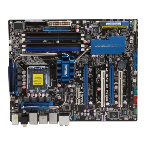
Page 29: Motherboard Layout
PCI2 CR2032 3V Lithium Cell CMOS Power VT6308S DET_X16_4 PCIEX16_4 CHA_FAN2 CLRTC SB_PWR BIOS CHASSIS PANEL IE1394_2 COM1 USB910 USB78 AAFP CHA_FAN3 Refer to 2.7 Connectors for more information about rear panel connectors and internal connectors. ASUS P5E64 WS Evolution... -
Page 30: Layout Contents
2.2.4 Layout contents Slots Page DDR3 DIMM slots 2-13 PCI slots 2-21 PCI Express x4 slot 2-21 PCI Express 2.0 x16 slots (blue) 2-21 Universal PCI Express x16 slots (black) 2-21 Jumper Page Clear RTC RAM (3-pin CLRTC_EN) 2-23 Rear panel connectors Page PS/2 keyboard port (purple) 2-24... - Page 31 Chassis intrusion connector (4-1 pin CHASSIS) 2-32 Front panel audio connector (10-1 pin AAFP) 2-33 TPM connector (20-1 pin TPM) 2-33 ATX power connectors (24-pin EATXPWR, 8-pin EATX12V) 2-34 System panel connector (20-8 pin PANEL) 2-35 ASUS Q-connector (system panel) 2-36 ASUS P5E64 WS Evolution...
-
Page 32: Central Processing Unit (Cpu)
ASUS will shoulder the cost of repair only if the damage is shipment/transit-related. • Keep the cap after installing the motherboard. ASUS will process Return Merchandise Authorization (RMA) requests only if the motherboard comes with the cap on the LGA775 socket. -
Page 33: Installing The Cpu
To prevent damage to the socket pins, do not remove the PnP cap unless you are installing a CPU. Lift the load lever in the direction of the arrow to a 135º angle. ASUS P5E64 WS Evolution... - Page 34 Lift the load plate with your thumb and forefinger to a 100º angle (A), then push the PnP cap from the load plate window to remove (B). Load plate Alignment key Position the CPU over the socket, making sure that the gold triangle is on the bottom-left corner of the socket then fit the socket...
-
Page 35: Installing The Cpu Heatsink And Fan
CPU fan connector. Motherboard hole Fastener Narrow end of the groove Make sure to orient each fastener with the narrow end of the groove pointing outward. (The photo shows the groove shaded for emphasis.) ASUS P5E64 WS Evolution... - Page 36 Push down two fasteners at a time in a diagonal sequence to secure the heatsink and fan assembly in place. Connect the CPU fan cable to the connector on the motherboard labeled CPU_FAN. CPU_FAN ® P5E64 WS EVOLUTION P5E64 WS Evolution CPU fan connector Do not forget to connect the CPU fan connector! Hardware monitoring errors can occur if you fail to plug this connector.
- Page 37 Rotate each fastener counterclockwise. Pull up two fasteners at a time in a diagonal sequence to disengage the heatsink and fan assembly from the motherboard. Carefully remove the heatsink and fan assembly from the motherboard. ASUS P5E64 WS Evolution 2-11...
- Page 38 Rotate each fastener clockwise to ensure correct orientation when reinstalling. Narrow end of the groove The narrow end of the groove should point outward after resetting. (The photo shows the groove shaded for emphasis.) Refer to the documentation in the boxed or stand-alone CPU fan package for detailed information on CPU fan installation.
-
Page 39: System Memory
The figure illustrates the location of the DDR3 DIMM sockets: ® P5E64 WS EVOLUTION P5E64 WS Evolution 240-pin DDR3 DIMM sockets Channel Sockets Channel A DIMM_A1 and DIMM_A2 Channel B DIMM_B1 and DIMM_B2 ASUS P5E64 WS Evolution 2-13... -
Page 40: Memory Configurations
2.4.2 Memory configurations You may install 512 MB, 1 GB, and 2 GB unbuffered DDR3 DIMMs into the DIMM sockets. Recommended Memory Configurations Sockets Mode DIMM_A1 DIMM_A2 DIMM_B1 DIMM_B2 Populated — — — Single-Channel — — Populated — Dual-channel (1) Populated —... - Page 41 Chip Size Vendor Chip No. Part No. Brand 1024MB SAMSUNG K4B1G0846C-ZCF8 SAMSUNG M378B2873CZ0-CG9 • • 1024MB Kingston J5308BASE-DG-E ELPIDA KVR1333D3N8/1G • • 1024MB Kingston Heat-Sink Package KHX11000D3LL/1G • 1024MB CORSAIR Heat-Sink Package CM3X1024-1333C9DHX • • ASUS P5E64 WS Evolution 2-15...
- Page 42 P5E64 WS Evolution Motherboard Qualified Vendors Lists (QVL) DDR3-1067MHz capability DIMM socket support (Optional) Chip Size Vendor Chip No. Part No. Brand 512MB Qimonda IDSH51-03A1F1C-10F QIMONDA IMSH51U03A1F1C-10F • • • 1024MB Qimonda IDSH51-03A1F1C-10F QIMONDA IMSH1GU13A1F1C-10F • • 512MB ELPIDA J5308BASE-AC-E ELPIDA EBJ51UD8BAFA-AG-E •...
-
Page 43: Memory Configuration
Dual-channel memory configuration. • C*: Supports four modules inserted into both the blue slots and the black slots as two pairs of Dual-channel memory configuration. Visit the ASUS website for the latest QVL. ASUS P5E64 WS Evolution 2-17... -
Page 44: Installing A Dimm
2.4.3 Installing a DIMM Unplug the power supply before adding or removing DIMMs or other system components. Failure to do so can cause severe damage to both the motherboard and the components. To install a DIMM: Unlock a DIMM socket by pressing the retaining clips DDR3 DIMM notch outward. -
Page 45: Expansion Slots
IRQ” or that the cards do not need IRQ assignments. Otherwise, conflicts will arise between the two PCI groups, making the system unstable and the card inoperable. Refer to the table on the next page for details. ASUS P5E64 WS Evolution 2-19... -
Page 46: Interrupt Assignments
2.5.3 Interrupt assignments Priority Standard function System timer Keyboard controller – Re-direct to IRQ#9 IRQ holder for PCI steering* Communications port (COM1)* IRQ holder for PCI steering* Floppy disk controller IRQ holder for PCI steering* System CMOS/Real Time Clock IRQ holder for PCI steering* IRQ holder for PCI steering* IRQ holder for PCI steering* PS/2 compatible mouse port*... -
Page 47: Pci Slots
Universal PCIe x16_4 slot (black, @ x4 or x1) PCI_2 slot PCIe 2.0 x16_3 slot (blue, @ x16) PCI_1 slot Universal PCIe x16_2 slot (black, @ x4 or x1) PCIe 2.0 x16_1 slot (blue, @ x16) PCI Express x4_1 slot ASUS P5E64 WS Evolution 2-21... -
Page 48: Ai Slot Detector
• If you install two VGA cards, we recommend that you plug the rear chassis fan cable to the motherboard connector labeled CHA_FAN3 or CHA_FAN4 for better thermal environment. See page 2-32 for the connector location. • Some PCI Express devices cannot operate on x4/x1 mode. 2.5.8 AI Slot Detector This motherboard comes with on-board LEDs that light up when the PCIE/... -
Page 49: Jumpers
• Due to the chipset limitation, AC power off is required prior using C.P.R. function. You must turn off and on the power supply or unplug and plug the power cord before reboot the system. ASUS P5E64 WS Evolution 2-23... -
Page 50: Connectors
Connectors 2.7.1 Rear panel connectors PS/2 keyboard port (purple) PS/2 keyboard port (purple). This port is for a PS/2 keyboard. Coaxial S/PDIF Out port. This port connects an external audio output device via a coaxial S/PDIF cable. LAN1 (RJ-45) port. Supported by Marvell Gigabit LAN controller, this port ®... - Page 51 15. Optical S/PDIF Out port. This port connects an external audio output device via an optical S/PDIF cable. 16. USB 2.0 ports 5 and 6. These two 4-pin Universal Serial Bus (USB) ports are available for connecting USB 2.0 devices. ASUS P5E64 WS Evolution 2-25...
-
Page 52: Internal Connectors
2.7.2 Internal connectors Floppy disk drive connector (34-1 pin FLOPPY) This connector is for the provided floppy disk drive (FDD) signal cable. Insert one end of the cable to this connector, then connect the other end to the signal connector at the back of the floppy disk drive. FLOPPY NOTE: Orient the red markings on the floppy ribbon cable to PIN 1. - Page 53 Ultra DMA cable connector. This prevents incorrect insertion when you connect the IDE cable. • Use the 80-conductor IDE cable for Ultra DMA 133/100 IDE devices. If any device jumper is set as “Cable-Select,” make sure all other device jumpers have the same setting. ASUS P5E64 WS Evolution 2-27...
-
Page 54: Serial Ata Hard Disk Drive Connection
ICH9R Serial ATA connectors [blue] (7-pin SATA1-SATA6) These connectors are for the Serial ATA signal cables for Serial ATA hard disk drives and optical disk drives. SATA1 SATA2 SATA2 SATA1 ® SATA3 SATA4 SATA3 SATA4 P5E64 WS EVOLUTION P5E64 WS Evolution P5B SATA Connectors SATA connectors SATA6... - Page 55 Before creating a RAID set using Serial ATA hard disks, make sure that you have connected the Serial ATA signal cables and installed Serial ATA hard disk drives; otherwise, you cannot enter the Marvell RAID utility and SATA BIOS setup during POST. ASUS P5E64 WS Evolution 2-29...
- Page 56 Never connect a 1394 cable to the USB connectors. Doing so will damage the motherboard! You can connect the USB cable to ASUS Q-Connector (USB, blue) first, and then install the Q-Connector (USB) to the USB connector onboard. IEEE 1394a port connector (10-1 pin IE1394_1) This connector is for an IEEE 1394a port.
- Page 57 This connector is for a serial (COM) port. Connect the serial port module cable to this connector, then install the module to a slot opening at the back of the system chassis. COM1 PIN 1 ® P5E64 WS EVOLUTION P5E64 WS Evolution COM port connector ASUS P5E64 WS Evolution 2-31...
- Page 58 Rotation +12V +12V P5E64 WS Evolution Fan connectors Only the CPU-FAN and CHA-FAN 1-2 connectors support the ASUS Q-FAN 2 feature. 10. Chassis intrusion connector (4-1 pin CHASSIS) This connector is for a chassis-mounted intrusion detection sensor or switch. Connect one end of the chassis intrusion sensor or switch cable to this connector.
- Page 59 This connector supports a Trusted Platform Module (TPM) system, which can securely store keys, digital certificates, passwords, and data. A TPM system also helps enhance network security, protects digital identities, and ensures platform integrity. ® P5E64 WS EVOLUTION P5E64 WS Evolution TPM connector ASUS P5E64 WS Evolution 2-33...
- Page 60 CPU: Intel Pentium Extreme 3.73GHz ® ® Memory: 512 MB DDR3 (x4) Graphics card: ASUS EAX1900XT Parallel ATA device: IDE hard disk drive Serial ATA device: SATA hard disk drive (x2) Optical drive: DVD-RW 2-34 Chapter 2: Hardware information...
-
Page 61: System Panel Connector
BIOS settings. Pressing the power switch for more than four seconds while the system is ON turns the system OFF. • Reset button (2-pin RESET) This 2-pin connector is for the chassis-mounted reset button for system reboot without turning off the system power. ASUS P5E64 WS Evolution 2-35... - Page 62 15. Q-Connector (system panel) You can use ASUS Q-Connector to connect / disconnect chassis front panel cables by only a few steps. Directions below shows how to install ASUS Q- Connector. Step1. Connect correct front panel to ASUS Q- Connector first. You can refer to the marking on Q-Connector itself to know the detail pin definition.
-
Page 63: G.p. Diagnosis Card Installation
2-33 for exact connector location). With the LEDs of the diagnosis card facing to the DIMM sockets, align the card connector with the TPM connector and press firmly until the card sits on the connector completely. ASUS P5E64 WS Evolution 2-37... -
Page 64: G.p. Diagnosis Card Check Codes
You may also install the G.P. Diagnosis card via a bundled 90- degree TPM adaptor for a more flexible application. 2.8.3 G.P. Diagnosis card check codes Initiate chip Detect IDE Enable IO device for bootlock Initiate option ROM Check and wake up system Show post error Enter BIOS setup Prepare system for memory... -
Page 65: Chapter 3: Powering Up
This chapter describes the power up sequence, the vocal POST messages, Chapter 3: and ways of shutting down the system. Powering up... -
Page 66: Starting Up For The First Time
Chapter summary Starting up for the first time ............3-1 Turning off the computer ............. 3-2 ASUS P5E64 WS Evolution... -
Page 67: Starting Up For The First Time
One continuous beep followed by three No VGA detected short beeps One continuous beep followed by four Hardware component failure short beeps At power on, hold down the <Delete> key to enter the BIOS Setup. Follow the instructions in Chapter 4. ASUS P5E64 WS Evolution... -
Page 68: Turning Off The Computer
Turning off the computer 3.2.1 Using the OS shut down function ® If you are using Windows XP or later version: Click the Start button then select Turn Off Computer. Click the Turn Off button to shut down the computer. ®... -
Page 69: Chapter 4: Bios Setup
This chapter tells how to change the system settings through the BIOS Setup menus. Detailed descriptions of the BIOS parameters are also provided. Chapter 4: BIOS setup... - Page 70 Managing and updating your BIOS ..........4-1 BIOS setup program ..............4-9 Main menu .................. 4-12 Ai Tweaker menu ............... 4-17 Advanced menu ................. 4-25 Power menu ................4-31 Boot menu .................. 4-35 Tools menu ................. 4-39 Exit menu ..................4-42 ASUS P5E64 WS Evolution...
-
Page 71: Managing And Updating Your Bios
ASUS Update (Updates the BIOS in Windows environment.) ® ASUS EZ Flash 2 (Updates the BIOS using a floppy disk or USB flash disk.) ASUS AFUDOS (Updates the BIOS using a bootable floppy disk.) ASUS CrashFree BIOS 3 (Updates the BIOS using a bootable floppy disk, USB flash disk or the motherboard support DVD when the BIOS file fails or gets corrupted.) - Page 72 To update the BIOS through the Internet: desktop by clicking Start Launch the ASUS Update utility from the Windows ® > Programs > ASUS > ASUSUpdate > ASUSUpdate. The ASUS Update main window appears. Select Update BIOS from the Select the ASUS FTP site nearest...
- Page 73 To update the BIOS through a BIOS file: Launch the ASUS Update utility from the Windows desktop by clicking Start ® > Programs > ASUS > ASUSUpdate > ASUSUpdate. The ASUS Update main window appears. Select Update BIOS from a file option from the drop-down menu, then click Next.
-
Page 74: Creating A Bootable Floppy Disk
4.1.2 Creating a bootable floppy disk Do either one of the following to create a bootable floppy disk. DOS environment a. Insert a 1.44MB floppy disk into the drive. b. At the DOS prompt, type format A:/S then press <Enter>. Windows XP environment ®... -
Page 75: Asus Ez Flash 2 Utility
4.1.3 ASUS EZ Flash 2 utility The ASUS EZ Flash 2 feature allows you to update the BIOS without having to go through the long process of booting from a floppy disk and using a DOS-based utility. The EZ Flash 2 utility is built in the BIOS chip so it is accessible by pressing <Alt>... -
Page 76: Afudos Utility
Updating the BIOS file To update the BIOS file using the AFUDOS utility: Visit the ASUS website (www.asus.com) and download the latest BIOS file for the motherboard. Save the BIOS file to a bootable floppy disk. Chapter 4: BIOS setup... - Page 77 A:\>afudos /iP5E64WE.ROM The utility verifies the file and starts updating the BIOS. A:\>afudos /iP5E64WE.ROM AMI Firmware Update Utility - Version 1.19(ASUS V2.07(03.11.24BB)) Copyright (C) 2002 American Megatrends, Inc. All rights reserved. WARNING!! Do not turn off power during flash BIOS Reading file ..
-
Page 78: Asus Crashfree Bios 3 Utility
4.1.5 ASUS CrashFree BIOS 3 utility The ASUS CrashFree BIOS 3 is an auto recovery tool that allows you to restore the BIOS file when it fails or gets corrupted during the updating process. You can update a corrupted BIOS file using the motherboard support DVD or the USB flash disk that contains the updated BIOS file. -
Page 79: Bios Setup Program
The BIOS setup screens shown in this section are for reference purposes only, and may not exactly match what you see on your screen. • Visit the ASUS website (www.asus.com) to download the latest BIOS file for this motherboard. ASUS P5E64 WS Evolution... -
Page 80: Bios Menu Screen
4.2.1 BIOS menu screen Menu items Menu bar Configuration fields General help BIOS SETUP UTILITY Main Ai Tweaker Advanced Power Boot Tools Exit Use [ENTER], [TAB] System Time [10:55:25] or [SHIFT-TAB] to System Date [Wed 01/09/2008] select a field. Legacy Diskette A [1.44M, 3.5 in] Language [English]... -
Page 81: Menu Items
Up/Down arrow keys or <Page Up> /<Page Down> keys to display the other items on the screen. 4.2.9 General help Pop-up window At the top right corner of the menu screen Scroll bar is a brief description of the selected item. ASUS P5E64 WS Evolution 4-11... -
Page 82: Main Menu
Main menu When you enter the BIOS Setup program, the Main menu screen appears, giving you an overview of the basic system information. Refer to section 4.2.1 BIOS menu screen for information on the menu screen items and how to navigate through them. BIOS SETUP UTILITY Main Ai Tweaker... -
Page 83: Sata 1~6
When set to [Disabled], the data transfer from and to the device occurs one sector at a time. Configuration options: [Disabled] [Auto] PIO Mode [Auto] Allows you to select the data transfer mode. Configuration options: [Auto] [0] [1] [2] [3] [4] ASUS P5E64 WS Evolution 4-13... -
Page 84: Sata Configuration
DMA Mode [Auto] Selects the DMA mode. Configuration options: [Auto] [SWDMA0] [SWDMA1] [SWDMA2] [MWDMA0] [MWDMA1] [MWDMA2] [UDMA0] [UDMA1] [UDMA2] [UDMA3] [UDMA4] [UDMA5] SMART Monitoring [Auto] Allows you to enable or disable the HDD Self-Monitoring Analysis and Reporting Technology (SMART) feature. Configuration options: [Auto] [Disabled] [Enabled] 32Bit Data Transfer [Enabled] Enables or disables 32-bit data transfer. -
Page 85: Ahci Configuration
SATA Port1 [Auto] Allows you to select the type of device connected to the system. Configuration options: [Auto] [Not Installed] SMART Monitoring [Enabled] Allows you to set the Self-Monitoring, Analysis and Reporting Technology. Configration options: [Disabled] [Enabled] ASUS P5E64 WS Evolution 4-15... -
Page 86: System Information
4.3.8 System Information This menu gives you an overview of the general system specifications. The BIOS automatically detects the items in this menu. BIOS SETUP UTILITY Main ASUS BIOS Version : 0108 Build Date : 12/18/07 Processor Type : Intel(R) Core(TM)2 Duo CPU @ 3.00GHz... -
Page 87: Ai Tweaker Menu
Loads the optimal settings for the system. X.M.P. If you install memory module(s) supporting the eXtreme Memory Profile (X.M.P.) Technology, choose this item to set the profile(s) supported by your memory module(s) for optimizing the system performance. ASUS P5E64 WS Evolution 4-17... -
Page 88: Cpu Ratio Setting
The configuration options for the following sub-item vary depending on the DIMMs you install on the motherboard. eXtreme Memory Profile [Disabled] This item appears only when you set the Ai Overclock Tuner item to [X.M.P.]. Allows you to select the X.M.P. mode supported by your Memory module. -
Page 89: Dram Frequency
4.4.5 DRAM Command Rate [Auto] Set this item to [1N] to provide possibility to accelerate DRAM performance or [2N] to enhance DRAM overclocking ability. Configuration options: [Auto] [1N] [2N] ASUS P5E64 WS Evolution 4-19... -
Page 90: Dram Cmd Skew On Channel A/B
4.4.6 DRAM CMD Skew on Channel A/B [Auto] These items are adjustable only when you set the DRAM Command Rate item to [1N] and may help enhancing DRAM stability on 1N mode. Configuration options: [Auto] [Advance 175ps] [Advance 150ps] [Advance 125ps] [Advance 100ps] [Advance 75ps] [Advance 50ps] [Advance 25ps] [Normal] [Delay 25ps] [Delay 50ps] [Delay 75ps] [Delay 100ps] [Delay 125ps] [Delay 150ps] [Delay 175ps]... - Page 91 Configuration options: [Auto] [ 1 DRAM Clocks]~[15 DRAM Clocks] PRE to PRE Delay [Auto] Configuration options: [Auto] [ 1 DRAM Clocks]~[ 3 DRAM Clocks] ALL PRE to ACT Delay [Auto] Configuration options: [Auto] [ 1 DRAM Clocks]~[15 DRAM Clocks] ASUS P5E64 WS Evolution 4-21...
-
Page 92: Dram Static Read Control
ALL PRE to REF Delay [Auto] Configuration options: [Auto] [ 1 DRAM Clocks]~[15 DRAM Clocks] 4.4.9 DRAM Static Read Control [Auto] Adjusting this item might enhance DRAM overclocking ability. Configuration options: [Auto] [Disabled] [Enabled] 4.4.10 DRAM Dynamic Write Control [Auto] Adjusting this item might enhance DRAM overclocking ability. -
Page 93: Cpu Pll Voltage
The system may need better cooling system to work stably under high voltage settings. Blue Yellow Purple CPU PLL Voltage 1.50V~1.78V 1.80V~2.00V 2.02V~2.20V 2.22V~2.78V FSB Termination 1.20V~1.38V 1.40V~1.50V Voltage DRAM Voltage 1.50V~1.68V 1.70V~1.90V 1.92V~2.10V 2.12V~2.78V NB Voltage 1.25V~1.41V 1.43V~1.55V 1.57V~1.73V 1.75V~2.21V* ASUS P5E64 WS Evolution 4-23... -
Page 94: Sb Voltage
4.4.18 SB Voltage [Auto] Allows you to set the South Bridge voltage. The values range from 1.05V to 1.20V with a 0.15V interval. 4.4.19 Clock Over-Charging Voltage [Auto] Allows you to set the Clock Over-Charging voltage. The values range from 0.70V to 1.00V with a 0.10V interval. -
Page 95: Advanced Menu
[Enabled] Vanderpool Technology [Enabled] Select Screen Execute Disable Bit [Enabled] Select Item Max CPUID Value Limit [Disabled] Change Option Intel(R) SpeedStep(TM) Tech. [Enabled] General Help Save and Exit Exit v02.61 (C)Copyright 1985-2007, American Megatrends, Inc. ASUS P5E64 WS Evolution 4-25... - Page 96 CPU Ratio Setting [Auto] This item allows you to set the ratio between CPU Core Clock and FSB Frequency. The value is adjusted by typing the desired values using the numeric keypad and press the <Enter> key. You can also use the <+> and <-> keys to adjust the value. To restore the default setting, type [auto] using the keyboard and press the <Enter>...
-
Page 97: Chipset
Allows you to decide which graphics controller to use as the primary boot device. Configuration options: [PCI/PEG] [PEG/PCI] PEG Port Control [Auto] Configuration options: [Auto] [Disabled] PEG Force x1 [Disabled] This item appears when the PEG Port Control item is set to [Auto]. Configuration options: [Enabled] [Disabled] ASUS P5E64 WS Evolution 4-27... -
Page 98: Onboard Devices Configuration
4.5.3 Onboard Devices Configuration BIOS SETUP UTILITY Advanced Onboard Device Configuraiton Enable or Disable High Definition Audio High Definition Audio [Enabled] Controller Front Panel Type [HD Audio] Marvell IDE/eSATA [Legacy Mode] IDE/eSATA Boot ROM [Enabled] PCIE GigaBit LAN1 [Enabled] LAN Boot ROM [Disabled] PCI GigaBit LAN2 [Enabled]... -
Page 99: Usb Configuration
Allows you to enable or disable the USB functions. The following sub-items appear when this item is set to [Enabled]. Configuration options: [Disabled] [Enabled] USB 2.0 Controller [Enabled] Allows you to enable or disable the USB 2.0 controller. Configuration options: [Enabled] [Disabled] ASUS P5E64 WS Evolution 4-29... -
Page 100: Pci Pnp
USB 2.0 Controller Mode [HiSpeed] Allows you to set the USB 2.0 controller mode to HiSpeed (480 Mbps) or FullSpeed (12 Mbps). This item appears only when you enable the USB 2.0 Controller item. Configuration options: [FullSpeed ] [HiSpeed ] BIOS EHCI Hand-off [Enabled] Allows you to enable support for operating systems without an EHCI hand-off feature. -
Page 101: Power Menu
Allows you to enable or disable the Advanced Configuration and Power Interface (ACPI) support in the Advanced Programmable Interrupt Controller (APIC). When set to Enabled, the ACPI APIC table pointer is included in the RSDT pointer list. Configuration options: [Disabled] [Enabled] ASUS P5E64 WS Evolution 4-31... -
Page 102: Apm Configuration
4.6.5 APM Configuration BIOS SETUP UTILITY Power APM Configuration <Enter> to select whether or not to restart the system Restore on AC Power Loss [Power Off] after AC power loss. Power On By RTC Alarm [Disabled] Power On By External Modems [Disabled] Power On By PCI Devices [Disabled]... -
Page 103: Hardware Monitor
[ 3.296V] Select Item Voltage [ 5.094V] Change Field Voltage [11.616V] General Help ASUS Advanced Q-Fan Control Save and Exit Exit CPU Q-Fan Control [Disabled] Chassis Q-Fan Profile [Disabled] v02.61 (C)Copyright 1985-2006, American Megatrends, Inc. v02.61 (C)Copyright 1985-2007, American Megatrends, Inc. - Page 104 CPU Voltage, 3.3V Voltage, 5V Voltage, 12V Voltage The onboard hardware monitor automatically detects the voltage output through the onboard voltage regulators. Select [Ignored] if you do not want to detect this item. CPU Q-Fan Control [Disabled] Allows you to enable or disable the CPU Q-Fan controller. Configuration options: [Disabled] [Enabled] The CPU Fan Profile item appears when you enable the CPU Q-Fan Control feature.
-
Page 105: Boot Menu
These items specify the boot device priority sequence from the available devices. The number of device items that appears on the screen depends on the number of devices installed in the system. Configuration options: [1st FLOPPY DRIVE] [Hard Drive] [ATAPI CD-ROM] [Disabled] ASUS P5E64 WS Evolution 4-35... -
Page 106: Boot Settings Configuration
This allows you to enable or disable the full screen logo display feature. Configuration options: [Disabled] [Enabled] Set this item to [Enabled] to use the ASUS MyLogo2™ feature. AddOn ROM Display Mode [Force BIOS] Sets the display mode for option ROM. -
Page 107: Security
Time Clock (RTC) RAM. See section 2.6 Jumper for information on how to erase the RTC RAM. After you have set a supervisor password, the other items appear to allow you to change other security settings. ASUS P5E64 WS Evolution 4-37... -
Page 108: Change User Password
BIOS SETUP UTILITY Boot <Enter> to change Security Settings password. <Enter> again to Supervisor Password :Installed disabled password. User Password :Installed Change Supervisor Password User Access Level [Full Access] Change User Password Clear User Password Password Check [Setup] Select Screen Select Item Enter Change General Help... -
Page 109: Tools Menu
4.8.1 ASUS EZ Flash 2 Allows you to run ASUS EZ Flash 2. When you press <Enter>, a confirmation message appears. Use the left/right arrow key to select between [Ok] or [Cancel], then press <Enter> to confirm your choice. Please see page 4-5, section 4.1.3 for details. -
Page 110: Asus O.c. Profile
4.8.2 ASUS O.C. Profile This item allows you to store or load multiple BIOS settings. BIOS SETUP UTILITY Tools O.C. PROFILE Configuration Save to Profile 1 O.C. Profile 1 Status :Not Installed O.C. Profile 2 Status :Not Installed Save to Profile 1... -
Page 111: Ai Net 2
Allows you to enable or disable LAN cable check during POST. When enabled, the menu reports the cable faults or shorts, and displays the point (length) where the faults or shorts are detected. Configuration options: [Disabled] [Enabled] ASUS P5E64 WS Evolution 4-41... -
Page 112: Exit Menu
Exit menu The Exit menu items allow you to load the optimal or failsafe default values for the BIOS items, and save or discard your changes to the BIOS items. BIOS SETUP UTILITY Main Ai Tweaker Advanced Power Boot Tools Exit E x i t s y s t e m s e t u p a f t e r s a v i n g t h e... -
Page 113: Chapter 5: Software Support
This chapter describes the contents of the support CD that comes with the motherboard package. Chapter 5: Software support... - Page 114 Chapter summary Installing an operating system ........... 5-1 Support DVD information ............5-1 Software information ..............5-9 RAID configurations ..............5-33 Creating a RAID driver disk ............5-44 ASUS P5E64 WS Evolution...
-
Page 115: Installing An Operating System
The contents of the support DVD are subject to change at any time without notice. Visit the ASUS website(www.asus.com) for updates. 5.2.1 Running the support DVD Place the support DVD to the optical drive. The DVD automatically displays the Drivers menu if Autorun is enabled in your computer. -
Page 116: Drivers Menu
61xx SATA RAID controller driver. ® USB 2.0 Driver Installs the Universal Serial Bus 2.0 (USB 2.0) driver. ASUS EPU Driver + AI Gear 3 Utility Installs the ASUS EPU driver and AI Gear 3 utility. Chapter 5: Software support... -
Page 117: Utilities Menu
Click to display the next page Click to return to the previous page ASUS InstAll - Installation Wizard for Utilities Installs all of the utilities through the Installation Wizard. Marvell Yukon VCT Application Installs the Marvell Yukon Virtual Cable Tester (VCT) Application. - Page 118 Installs the ASUS AI Suite. ASUS Update Allows you to download the latest version of the BIOS from the ASUS website. Before using the ASUS Update, make sure that you have an Internet connection so you can connect to the ASUS website.
-
Page 119: Make Disk Menu
Intel ICH9 32/64 bit RAID/AHCI Driver Allows you to create an Intel ICH9R RAID/AHCI driver disk for a 32/64-bit system. ® Marvell 61xx 32/64bit Driver Allows you to create a Marvell 61xx SATA RAID driver disk for a 32/64-bit system. ® ASUS P5E64 WS Evolution... -
Page 120: Manual Menu
Reader from the Utilities tab before opening a user manual ® ® file. 5.2.6 ASUS Contact information Click the Contact tab to display the ASUS contact information. You can also find this information on the inside front cover of this user guide. Chapter 5: Software support... -
Page 121: Other Information
DVD. Click an icon to display the specified information. Motherboard Info Displays the general specifications of the motherboard. Browse this DVD Displays the support DVD contents in graphical format. ASUS P5E64 WS Evolution... -
Page 122: Technical Support Form
Technical support Form Displays the ASUS Technical Support Request Form that you have to fill out when requesting technical support. Filelist Displays the contents of the support DVD and a brief description of each in text format. Chapter 5: Software support... -
Page 123: Software Information
5.3.1 ASUS MyLogo2™ The ASUS MyLogo2™ utility lets you customize the boot logo. The boot logo is the image that appears on screen during the Power-On Self-Tests (POST). The ASUS MyLogo2™ is automatically installed when you install the ASUS Update utility from the Support DVD. - Page 124 Ratio box. When the screen returns to the ASUS Update utility, flash the original BIOS to load the new boot logo. 10. After flashing the BIOS, restart the computer to display the new boot logo during POST.
-
Page 125: Ai Net2
LAN cable(s) connected to the LAN port(s). • If you want the system to check the status of the LAN cable before entering the OS, enable the item Post Check LAN Cable in the BIOS Setup. ASUS P5E64 WS Evolution P5E64 WS Evolution 5-11... -
Page 126: Asus Pc Probe Ii
To launch the PC Probe II from the Windows ® > ASUS > PC Probe II > PC Probe II v1.xx.xx. The PC Probe II main window appears. After launching the application, the PC Probe II icon appears in the Windows®... - Page 127 When displayed, the monitor panel for that sensor also turns red. Refer to the Monitor panels section for details. Preference You can customize the application using the Preference section in the main window. Click the box before each preference to activate or deactivate. ASUS P5E64 WS Evolution P5E64 WS Evolution 5-13...
- Page 128 Hardware monitor panels The hardware monitor panels display the current value of a system sensor such as fan rotation, CPU temperature, and voltages. The hardware monitor panels come in two display modes: hexagonal (large) and rectangular (small). When you check the Enable Monitoring Panel option from the Preference section, the monitor panels appear on your computer’s desktop.
- Page 129 DMI browser Click to display the DMI (Desktop Management Interface) browser. This browser displays various desktop and system information. Click the plus sign (+) before DMI Information to display the available information. ASUS P5E64 WS Evolution P5E64 WS Evolution 5-15...
- Page 130 PCI browser Click to display the PCI (Peripheral Component Interconnect) browser. This browser provides information on the PCI devices installed on your system. Click the plus sign (+) before the PCI Information item to display available information. Usage The Usage browser displays real-time information on the CPU, hard disk drive space, and memory usage.
- Page 131 The Preference tab allows you to customize sensor alerts, or change the temperature scale. Loads the default Loads your saved threshold values for Cancels or configuration each sensor ignores your changes Applies your Saves your changes configuration ASUS P5E64 WS Evolution P5E64 WS Evolution 5-17...
-
Page 132: Asus Ai Suite
5.3.4 ASUS AI Suite ASUS AI Suite allows you to launch AI Gear 3, AI Booster, AI Nap, and Q-Fan 2 utilities easily. Install the ASUS EPU + AI Gear 3 Driver before the ASUS AI Suite utility. Otherwise, ASUS AI Suite will not function properly. - Page 133 Displays the CPU/ system temperature, CPU/memory/PCIE voltage, and CPU/ chassis fan speed Displays the FSB/CPU frequency Click on right corner of the expanded window to switch the temperature from degrees Centigrade to degrees Fahrenheit. ASUS P5E64 WS Evolution P5E64 WS Evolution 5-19...
-
Page 134: Asus Epu Utility -- Ai Gear 3
5.3.5 ASUS EPU Utility -- AI Gear 3 ASUS AI Gear 3 is a utility designed to configure and support all ASUS EPU (Energy Processing Unit) features. This easy-to-use utility provides four system performance profiles that adjusts the processor frequency and vCore voltage for different computing needs. -
Page 135: Asus Ai Nap
To switch the power button functions from AI Nap to shutting down, just right click the AI Suite icon on the OS taskbar, select AI Nap and click Use power button. Unclick the the item to switch the function back. ASUS P5E64 WS Evolution P5E64 WS Evolution 5-21... -
Page 136: Asus Q-Fan 2
5.3.7 ASUS Q-Fan 2 This ASUS Q-Fan 2 Control feature allows you to set the appropriate performance level of the CPU Q-Fan 2 or the Chassis Q-Fan 2 for more efficient system operation. After enabling the Q-Fan 2 function, the fans can be set to automatically adjust depending on the temperature, to decrease fan speed, or to achieve the maximum fan speed. -
Page 137: Asus Ai Booster
5.3.8 ASUS AI Booster The ASUS AI Booster application allows you to overclock the CPU speed in WIndows environment without the hassle of booting the BIOS. ® After installing AI Suite from the bundled Support DVD, you can launch the utility... -
Page 138: Ai Audio 2 (Soundmax ® High Definition Audio Utility)
5.3.9 AI Audio 2 (SoundMAX High Definition Audio utility) ® The ADI AD1988 High Definition Audio CODEC provides 8-channel audio capability through the SoundMAX audio utility with AudioESP™ software to ® deliver the ultimate audio experience on your PC. The software implements high quality audio synthesis/rendering, 3D sound positioning, and advanced voice-input technologies. - Page 139 Activating this function virtualizes surround sound with the vocal clarity added for use with stereo speakers or headphones. SoundMAX BlackHawk (AI Audio2) is available only under the Windows ® Vista™ operating system. ASUS P5E64 WS Evolution P5E64 WS Evolution 5-25...
- Page 140 Playback Settings To configure the playback settings, click the Playback button on the control panel. You can adjust the volume of the Speakers and SPDIF Interface or mute the audio. Preset settings Click and expand the drop-down menu to select your preferred Digital Signal Processing (DSP) preset.
- Page 141 Allows you to select an enhanced microphone input features, including No Filtering, Speakerphone, Voice Recording, and Directional Beam. More Settings Click for the further configurations. Equalizer Allows you to configure and customize all the DSP presets frequencies. ASUS P5E64 WS Evolution P5E64 WS Evolution 5-27...
- Page 142 Speakers Allows you to adjust the Speaker Trim and Speaker Delay. Bass Allows you to do the Bass management. Preferences Displays the preference options for this utility, version information, AudioESP, etc. 5-28 Chapter 5: Software support...
-
Page 143: Audio Setup Wizard
® Audio Setup Wizard By clicking the icon from the SoundMAX control panel, you can easily ® configure your audio settings. Simply follow succeeding screen instructions and begin enjoying High Definition Audio. ASUS P5E64 WS Evolution P5E64 WS Evolution 5-29... - Page 144 Jack configuration Adjust speaker volume This screen helps you configure your This screen helps you adjust speaker computer’s audio ports, depending on volume. Click the Test button to hear the audio devices you have installed. the changes you have made. Adjust microphone volume This screen helps you adjust microphone volume.
-
Page 145: Listening Environment Options
Click the General tab to choose your playback and recording devices, enable/ disable the AudioESP™ feature, and enable/disable digital output. Listening Environment options Click the Listening Environment tab to set up your speaker, acoustic environment, and enable/disable the Virtual Theater Surround function. ASUS P5E64 WS Evolution P5E64 WS Evolution 5-31... -
Page 146: Microphone Options
• The directional Array and Speaker Phone are purchased separately and function only when working with the ASUS Array Mic. • If you are using Windows Vista, you have to manually enable the directional Array and Speaker Phone function. -
Page 147: Raid Configurations
RAID driver from the support DVD to a floppy disk before you install an operating system to the selected hard disk drive. Refer to section 5.5 Creating a RAID driver disk for details. ASUS P5E64 WS Evolution 5-33... -
Page 148: Installing Serial Ata Hard Disks
5.4.2 Installing Serial ATA hard disks The motherboard supports Serial ATA hard disk drives. For optimal performance, install identical drives of the same model and capacity when creating a disk array. To install the SATA hard disks for a RAID configuration: Install the SATA hard disks into the drive bays. -
Page 149: Intel Matrix Storage Manager Option Rom Utility
The navigation keys at the bottom of the screen allow you to move through the menus and select the menu options. The RAID BIOS setup screens shown in this section are for reference only and may not exactly match the items on your screen. ASUS P5E64 WS Evolution 5-35... -
Page 150: Creating A Raid 0 Set (Striped)
Creating a RAID 0 set (striped) To create a RAID 0 set: From the utility main menu, select 1. Create RAID Volume, then press <Enter>. This screen appears. Intel(R) Matrix Storage Manager Option ROM v5.0.0.1032 ICH7R wRAID5 Copyright(C) 2003-05 Intel Corporation. All Rights Reserved. CREATE ARRAY MENU Name: Volume0... - Page 151 WARNING: ALL DATA ON SELECTED DISKS WILL BE LOST. Are you sure you want to create this volume? (Y/N): Press <Y> to create the RAID volume and return to the main menu, or <N> to go back to the Create Volume menu. ASUS P5E64 WS Evolution 5-37...
-
Page 152: Creating A Raid 1 Set (Mirrored)
Creating a RAID 1 set (mirrored) To create a RAID 1 set: From the utility main menu, select 1. Create RAID Volume, then press <Enter>. This screen appears. Intel(R) Matrix Storage Manager Option ROM v5.0.0.1032 ICH7R wRAID5 Copyright(C) 2003-05 Intel Corporation. All Rights Reserved. CREATE ARRAY MENU Name: Volume1... -
Page 153: Creating A Raid 10 Set
Key in the RAID volume capacity that you want then press <Enter> when the Capacity item is highlighted. The default value indicates the maximum allowed capacity. ASUS P5E64 WS Evolution 5-39... - Page 154 Creating a RAID 5 set (parity) To create a RAID 5 set: From the utility main menu, select 1. Create RAID Volume, then press <Enter>. This screen appears. Intel(R) Matrix Storage Manager Option ROM v5.0.0.1032 ICH7R wRAID5 Copyright(C) 2003-05 Intel Corporation. All Rights Reserved. CREATE ARRAY MENU Name: Volume5...
- Page 155 WARNING: ALL DATA ON SELECTED DISKS WILL BE LOST. Are you sure you want to create this volume? (Y/N): Press <Y> to create the RAID volume and return to the main menu or <N> to go back to the Create Volume menu. ASUS P5E64 WS Evolution 5-41...
-
Page 156: Deleting A Raid Set
Deleting a RAID set Take caution when deleting a RAID set. You will lose all data on the hard disk drives when you delete a RAID set. To delete a RAID set: From the utility main menu, select 2. Delete RAID Volume, then press <Enter>... -
Page 157: Resetting Disks To Non-Raid
Use the up/down arrow key to highlight the RAID set drive you want to reset, then press <Space> to select. Press <Enter> to reset the RAID set drive. A confirmation message appears. Press <Y> to reset the drive or press <N> to return to the utility main menu. ASUS P5E64 WS Evolution 5-43... -
Page 158: Creating A Raid Driver Disk
Creating a RAID driver disk ® A floppy disk with the RAID driver is required when installing Windows operating system on a hard disk drive that is included in a RAID set. For ® Windows Vista operating system, use either a floppy disk or a USB device with the RAID driver. - Page 159 To install the RAID driver in Windows Vista: ® Insert the floppy disk/USB device with RAID driver into the floppy disk drive/ USB port. During the OS installation, select Intel ICH9R. Follow the succeeding screen instructions to complete the installation. ASUS P5E64 WS Evolution 5-45...
- Page 160 5-46 Chapter 5: Software support...
-
Page 161: Ati
This chapter tells how to install ATI ® CrossFire™ graphics cards to avail of ATI’s Multi-Video Processing technology. Chapetr 6: CrossFire™ ® technology support... - Page 162 Chapter summary Overview ..................6-1 Installing CrossFire™ graphics cards ........6-2 Software information ..............6-5 ASUS P5E64 WS Evolution...
-
Page 163: Overview
Uninstall other graphics card drivers in your system To uninstall other graphics card drivers: Close all current applications. Go to Control Panel > Add/Remove Programs. Select your current graphics card driver/s. Select Add/Remove. Restart your system. ASUS P5E64 WS Evolution... -
Page 164: Installing Crossfire™ Graphics Cards
Installing CrossFire™ graphics cards Before installing a CrossFire™ system, refer to the user guide that came with the ATI CrossFire™ Edition graphics card. ® To install the graphics cards: Prepare one CrossFire™ Edition (Master) graphics card and one CrossFire™-ready (Slave) graphics card. Slave graphics card Master graphics card Insert the CrossFire™... - Page 165 Insert the CrossFire™-ready (Slave) graphics card into the PCI Express x16 black slot. Make sure that the card is properly seated on the slot. Connect an auxiliary power source from the power supply to the graphics cards. ASUS P5E64 WS Evolution...
- Page 166 Connect one end of the external cable to the Master graphics card. Connect the other end of the external cable to the Slave graphics card. Connect the loose end to the corresponding port on your monitor. Chapter 6: ATI MVP technology support ®...
-
Page 167: Software Information
Hardware Wizard window. Click Cancel. Place the CrossFire™ installation CD in your optical drive and install drivers from the opening menu. Click Next to continue from the installation window that appears. Read the License Agreement, then click Yes. ASUS P5E64 WS Evolution... - Page 168 Select the components that you want to install, then click Next. • Select Express to install the HydraVision™ multi-monitor and desktop management software, as well as the ATI driver. • Select Custom to individually choose desired software components. Setup prepares the installation wizard that will guide you to setup process.
-
Page 169: Using The Catalyst™ Control Center
Start > ATI Catalyst™ Control Center > ® Catalyst™ Control Center • Double-click the Catalyst™ Control Center desktop shortcut. • On the Windows task bar, double- ® click the Catalyst™ Control Center icon. ASUS P5E64 WS Evolution... - Page 170 The Catalyst™ Control Center Dialog Box View The Catalyst™ Control Center provides two views: Standard - simple view with wizards for beginners Advance - allows advanced users to access and configure the complete features of the software Set to Advance view to enable the CrossFire™ function. Chapter 6: ATI MVP technology support ®...
- Page 171 CrossFire™. Click OK to effect the setting. Hotkeys Click the Hotkeys tab on the Catalyst™ Control Center to access the Hotkeys Manager, which allows you to create key combinations as shortcuts for performing certain functions quickly. ASUS P5E64 WS Evolution...
- Page 172 Profiles Click the Profiles tab on the Catalyst™ Control Center to access the Profiles Manager, which allows you to create customized environments for your desktop, video, and 3D applications. Preferences Click the Preferences tab on the Catalyst™ Control Center to select a language, restore defaults, change skins, or enable/disable the System Tray icon.
- Page 173 Help Click the Help tab on the Catalyst™ Control Center to access the online help system, generate a Problem Report, and get the Catalyst™ Control Center version information. ASUS P5E64 WS Evolution 6-11...
- Page 174 6-12 Chapter 6: ATI MVP technology support ®...
-
Page 175: Appendix: Cpu Features
The Appendix describes the CPU features Appendix: and technologies that the motherboard supports. CPU features... -
Page 176: Chapter Summary
Chapter summary ® Intel EM64T ..................A-1 ® Enhanced Intel SpeedStep Technology (EIST) ......A-1 ® Intel Hyper-Threading Technology ...........A-3 ASUS P5E64 WS Evolution... -
Page 177: Intel ® Em64T
32-bit operating systems. • The motherboard comes with a BIOS file that supports EM64T. You can download the latest BIOS file from the ASUS website (www.asus.com/ support/download/) if you need to update the BIOS file. See Chapter 4 for details. -
Page 178: Using The Eist
A.2.2 Using the EIST To use the EIST feature: Turn on the computer, then enter the BIOS Setup. Go to the Advanced Menu, highlight CPU Configuration, then press <Enter>. Set the Intel(R) SpeedStep Technology item to [Automatic], then press <Enter>. Press <F10>... -
Page 179: Intel ® Hyper-Threading Technology
Power up the system and enter the BIOS Setup. Under the Advanced Menu, make sure that the item Hyper-Threading Technology is set to [Enabled]. The BIOS item appears only if you installed a CPU that supports Hyper- -Threading Technology. Restart the computer. ASUS P5E64 WS Evolution... - Page 180 Appendix: CPU features...