Table of Contents
Advertisement
Advertisement
Table of Contents

Related Manuals for Asus P5Q-VM DO


Summary of Contents for Asus P5Q-VM DO
- Page 1 P5E-VM DO...
- Page 2 Product warranty or service will not be extended if: (1) the product is repaired, modified or altered, unless such repair, modification of alteration is authorized in writing by ASUS; or (2) the serial number of the product is defaced or missing.
-
Page 3: Table Of Contents
Product highlights ............1-2 1.3.2 ASUS Features .............. 1-4 1.3.3 ASUS Special Features ..........1-5 1.3.4 ASUS Intelligent Overclocking Features ......1-6 Before you proceed ..............1-7 Motherboard overview ..............1-8 1.5.1 Placement direction ............1-8 1.5.2 Screw holes ..............1-8 1.5.3... - Page 4 Chapter 2: BIOS setup Managing and updating your BIOS ..........2-2 2.1.1 Creating a bootable floppy disk ........2-2 2.1.2 ASUS EZ Flash 2 utility ........... 2-3 2.1.3 AFUDOS utility ..............2-4 2.1.4 ASUS CrashFree BIOS 3 utility ........2-6 2.1.5...
- Page 5 2.6.2 Boot Settings Configuration .......... 2-39 2.6.3 Security ................. 2-40 Tools menu ................. 2-42 ASUS EZ Flash 2 ................. 2-42 Exit menu ..................2-43 Chapter 3: Software support Installing an operating system ........... 3-2 Support CD information .............. 3-2 3.2.1 Running the support CD ..........
-
Page 6: Notices
Notices Federal Communications Commission Statement This device complies with Part 15 of the FCC Rules. Operation is subject to the following two conditions: • This device may not cause harmful interference, and • This device must accept any interference received including interference that may cause undesired operation. -
Page 7: Safety Information
Safety information Electrical safety • To prevent electrical shock hazard, disconnect the power cable from the electrical outlet before relocating the system. • When adding or removing devices to or from the system, ensure that the power cables for the devices are unplugged before the signal cables are connected. -
Page 8: About This Guide
Refer to the following sources for additional information and for product and software updates. ASUS websites The ASUS website provides updated information on ASUS hardware and software products. Refer to the ASUS contact information. Optional documentation Your product package may include optional documentation, such as warranty flyers, that may have been added by your dealer. -
Page 9: Conventions Used In This Guide
Conventions used in this guide To make sure that you perform certain tasks properly, take note of the following symbols used throughout this manual. DANGER/WARNING: Information to prevent injury to yourself when trying to complete a task. CAUTION: Information to prevent damage to the components when trying to complete a task. -
Page 10: P5E-Vm Do Specifications Summary
Dual channel memory architecture * The chipset officially supports the memory frequency up to DDR2 800. Due to the tuning by ASUS exclusive technology, this motherboard natively supports up to DDR2 1066MHz. Refer to www.asus.com or user manual for Memory (QVL). - Page 11 - Memory tuning from 667 MHz up to 1066 MHz - PCI Express frequency tuning from 100 MHz up to 150 MHz at 1 MHz increment Overclocking Protection: - ASUS C.P.R. (CPU Parameter Recall) Other Features ASUS MyLogo 2 BIOS Features 32 Mb Flash ROM, AMI BIOS, PnP, DMI2.0, WfM2.0,...
- Page 12 1 x 4-pin ATX 12 V Power connector 1 x System panel connector (Q-Connector) Support CD Contents Drivers ASUS PC Probe II ASUS Update Anti-virus software (OEM version) Form Factor uATX form factor: 9.6” x 9.6” (24.4 cm x 24.4 cm)
-
Page 13: Chapter 1: Product Introduction
This chapter describes the motherboard features and the new technologies it supports. Product introduction... -
Page 14: Welcome
Green ASUS This motherboard and its packaging comply with the European Union’s Restriction on the use of Hazardous Substances (RoHS). This is in line with the ASUS vision of creating environment-friendly and recyclable products/packaging to safeguard consumers’ health while minimizing the impact on the environment. - Page 15 This motherboard supports the next-generation hard drives based on the Serial ATA (SATA) 3Gb/s storage specification, delivering enhanced scalability and doubling the bus bandwidth for high-speed data retrieval and saves. Easily backup photos, videos and other entertainment contents to external devices. See page 1-33 for details. ASUS P5E-VM DO...
-
Page 16: Asus Features
See page 1-30 for details. 1.3.2 ASUS Features ASUS Quiet Thermal Solution ASUS Quiet Thermal solution makes system more stable and enhances the overclocking capability. ASUS Advanced Q-Fan technology The ASUS Advanced Q-Fan technology is powered by Intel Quiet System Technology;... -
Page 17: Asus Special Features
ASUS EZ DIY ASUS EZ DIY feature collection provides you easy ways to install computer components, update the BIOS or back up your favorite settings. ASUS Q-Connector ASUS Q-Connector allows you to easily connect or disconnect the chassis front panel cables to the motherboard. -
Page 18: Asus Intelligent Overclocking Features
Due to chipset behavior, AC power off is required prior to using C.P.R. function. O.C. Profile The motherboard features the ASUS O.C. Profile that allows users to conveniently store or load multiple BIOS settings. The BIOS settings can be stored in the CMOS or a seperate file, giving users freedom to share and distribute their favorite settings. -
Page 19: Before You Proceed
The illustration below shows the location of the onboard LED. SB_PWR Standby Powered Power P5E-VM DO Onboard LED ASUS P5E-VM DO... -
Page 20: Motherboard Overview
Motherboard overview Before you install the motherboard, study the configuration of your chassis to ensure that the motherboard fits into it. Make sure to unplug the power cord before installing or removing the motherboard. Failure to do so can cause you physical injury and damage motherboard components. -
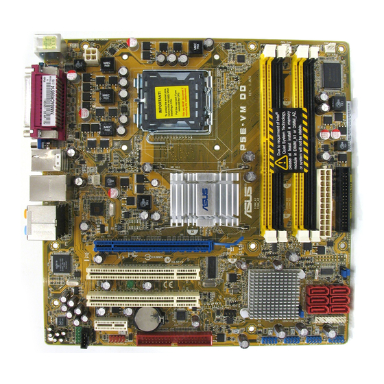
Page 21: Motherboard Layout
PCI2 SATA4 SATA3 SATA6 SATA5 CR2032 3V Lithium Cell JMB368 PCIEX1_1 CMOS Power ALC883 PANEL PRI_EIDE IE1394_2 USB1112 USB910 USB56 USB78 AAFP Refer to section 1.10 Connectors for more information about rear panel connectors and internal connectors. ASUS P5E-VM DO... -
Page 22: Layout Contents
1.5.4 Layout contents Slots Page DDR2 DIMM slots 1-19 PCI slots 1-27 PCI Express x 1 slot 1-27 PCI Express x16 slot 1-27 Jumper Page Clear RTC RAM (3-pin CLRTC) 1-28 Rear panel connectors Page PS/2 mouse port (green) 1-29 Parallel port 1-29 IEEE 1394a port... - Page 23 System panel connector (20-8-pin PANEL) 1-37 • System power LED (2-pin PLED) • Hard disk drive activity LED (2-pin IDE_LED) • System warning speaker (4-pin SPEAKER) • ATX power button/soft-off button (2-pin PWRSW) • Reset button (2-pin RESET) ASUS P5E-VM DO 1-11...
-
Page 24: Central Processing Unit (Cpu)
ASUS will shoulder the cost of repair only if the damage is shipment/transit-related. • Keep the cap after installing the motherboard. ASUS will process Return Merchandise Authorization (RMA) requests only if the motherboard comes with the cap on the LGA775 socket. -
Page 25: Installing The Cpu
To prevent damage to the socket pins, do not remove the PnP cap unless you are installing a CPU. Lift the load lever in the direction of the arrow to a 135º angle. ASUS P5E-VM DO 1-13... - Page 26 Lift the load plate with your thumb and forefinger to a 100º angle (A), then push the PnP cap from the load plate window to remove (B). Load plate Alignment key Position the CPU over the socket, making sure that the gold triangle is on the bottom-left corner of the socket then fit the socket...
-
Page 27: Installing The Cpu Heatsink And Fan
CPU fan connector. Motherboard hole Fastener Narrow end of the groove Make sure to orient each fastener with the narrow end of the groove pointing outward. (The photo shows the groove shaded for emphasis.) ASUS P5E-VM DO 1-15... - Page 28 Push down two fasteners at a time in a diagonal sequence to secure the heatsink and fan assembly in place. Connect the CPU fan cable to the connector on the motherboard labeled CPU_FAN. CPU_FAN CPU FAN PWM CPU FAN IN CPU FAN PWR P5E-VM DO CPU Fan Connector Do not forget to connect the CPU fan connector! Hardware monitoring errors...
-
Page 29: Uninstalling The Cpu Heatsink And Fan
Rotate each fastener counterclockwise. Pull up two fasteners at a time in a diagonal sequence to disengage the heatsink and fan assembly from the motherboard. Carefully remove the heatsink and fan assembly from the motherboard. ASUS P5E-VM DO 1-17... - Page 30 Rotate each fastener clockwise to ensure correct orientation when reinstalling. Narrow end of the groove The narrow end of the groove should point outward after resetting. (The photo shows the groove shaded for emphasis.) Refer to the documentation in the boxed or stand-alone CPU fan package for detailed information on CPU fan installation.
-
Page 31: System Memory
Channel A DIMM_A1 and DIMM_A2 Channel B DIMM_B1 and DIMM_B2 Install at least a memory module in DIMM_A1 or DIMM_A2 slot to support the Intel ® Quiet System Technology and for optimum performance. Otherwise, system will halt. ASUS P5E-VM DO 1-19... -
Page 32: Memory Configurations
1.7.2 Memory configurations You may install 256 MB, 512 MB, 1 GB, and 2 GB unbuffered non-ECC DDR2 DIMMs into the DIMM sockets. • You may install varying memory sizes in Channel A and Channel B. The system maps the total size of the lower-sized channel for the dual-channel configuration. - Page 33 T800UA12C4 • • • 1024MB Super Talent Heat-Sink Package T800UB1GC4 • • • 512MB NANYA NT5TU64M8BE-25C NT512T64U880BY-25C • • • 1024MB NANYA NT5TU64M8BE-25C NT1GT64U8HB0BY-25C • • • 512MB A3R12E3HEF641B9A05 AL6E8E63B8E1K • • • 1024MB A3R12E3HEF641B9A05 AL7E8E63B-8E1K ASUS P5E-VM DO 1-21...
- Page 34 Supports one pair of modules inserted into either the yellow slots or the black slots as one pair of Dual-channel memory configuration. Supports four modules inserted into both the yellow and black slots as two pairs of Dual-channel memory configuration. Visit the ASUS website for the latest DDR2-1066/800/667 MHz QVL. 1-22 Chapter 1: Product introduction...
-
Page 35: Installing A Dimm
DIMM. Support the DIMM lightly with your fingers when pressing the retaining clips. The DIMM might get damaged when it flips out with DDR2 DIMM notch extra force. Remove the DIMM from the socket. ASUS P5E-VM DO 1-23... -
Page 36: Expansion Slots
Expansion slots In the future, you may need to install expansion cards. The following sub-sections describe the slots and the expansion cards that they support. Make sure to unplug the power cord before adding or removing expansion cards. Failure to do so may cause you physical injury and damage motherboard components. -
Page 37: Interrupt Assignments
IRQ holder for PCI steering* IRQ holder for PCI steering* IRQ holder for PCI steering* PS/2 Compatible Mouse Port* Numeric Data Processor Primary IDE Channel Secondary IDE Channel * These IRQs are usually available for ISA or PCI devices. ASUS P5E-VM DO 1-25... - Page 38 IRQ assignments for this motherboard I.G.D. shared — — — — — — — HECI Host#1 shared — — — — — — — IDE-R Controller — — shared — — — — — KT Controller — shared — — —...
-
Page 39: Pci Slots
PCI Express x1 slot. 1.8.6 PCI Express x16 slot This motherboard supports PCI Express x16 graphic cards that comply with the PCI Express specifications. The figure shows a graphics card installed on the PCI Express x16 slot. ASUS P5E-VM DO 1-27... -
Page 40: Jumper
Jumper Clear RTC RAM (CLRTC) This jumper allows you to clear the Real Time Clock (RTC) RAM in CMOS. You can clear the CMOS memory of date, time, and system setup parameters by erasing the CMOS RTC RAM data. The onboard button cell battery powers the RAM data in CMOS, which include system setup information such as system passwords. -
Page 41: 1.10 Connectors
4-channel, 6-channel, and 8-channel configuration, the function of this port becomes Front Speaker Out. Microphone port (pink). This port connects a microphone. 10. Side Speaker Out port (gray). This port connects the side speakers in an 8-channel audio configuration. ASUS P5E-VM DO 1-29... -
Page 42: Internal Connectors
Refer to the audio configuration table below for the function of the audio ports in 2, 4, 6, or 8-channel configuration. Audio 2, 4, 6, or 8-channel configuration Port Headset 4-channel 6-channel 8-channel 2-channel Light Blue Line In Line In Line In Line In Lime... - Page 43 This connector is for a IEEE 1394a port. Connect the IEEE 1394a module cable to this connector, then install the module to a slot opening at the back of the system chassis. IE1394_2 P5E-VM DO IEEE 1394a Connector The IEEE 1394a module is purchased separately. ASUS P5E-VM DO 1-31...
-
Page 44: Ide Connectors
IDE connector (40-1 pin PRI_EIDE) The onboard IDE connector is for the Ultra DMA 133/100/66 signal cable. There are three connectors on each Ultra DMA 133/100/66 signal cable: blue, black, and gray. Connect the blue connector to the motherboard’s IDE connector, then select one of the following modes to configure your device. - Page 45 Optical drive audio connector (4-pin CD) These connectors allow you to receive stereo audio input from sound sources such as a CD-ROM, TV tuner, or MPEG card. (black) Right Audio Channel Ground Ground Left Audio Channel P5E-VM DO Internal Audio Connector ASUS P5E-VM DO 1-33...
- Page 46 Never connect a 1394 cable to the USB connectors. Doing so will damage the motherboard! You can connect the USB cable to ASUS Q-Connector (USB, blue) first, and then install the Q-Connector (USB) to the USB connector onboard. The USB module is purchased separately.
- Page 47 +12V Rotation P5E-VM DO Fan connectors Only the 4-pin CPU_FAN connectors support the ASUS Advanced Q-Fan feature. This motherboard does not support 3-pin CPU fan. Chassis intrusion connector (4-1 pin CHASSIS) This connector is for a chassis-mounted intrusion detection sensor or switch.
- Page 48 10. Front panel audio connector (10-1 pin AAFP) This connector is for a chassis-mounted front panel audio I/O module that supports either HD Audio or legacy AC`97 audio standard. Connect one end of the front panel audio I/O module cable to this connector. Azalia-compliant Legacy AC 97-compliant pin definition...
-
Page 49: System Panel Connector
BIOS settings. Pressing the power switch for more than four seconds while the system is ON turns the system OFF. • Reset button (2-pin RESET) This 2-pin connector is for the chassis-mounted reset button for system reboot without turning off the system power. ASUS P5E-VM DO 1-37... - Page 50 Q-Connector (system panel) ASUS Q-Connector allows you to easily to connect the chassis front panel cables to the motherboard. Perform these steps to install ASUS Q-Connector. Step1. Connect the front panel cables to their respective connectors on the ASUS Q- Connector.
-
Page 51: Chapter 2: Bios Setup
This chapter tells how to change the system settings through the BIOS Setup menus. Detailed descriptions of the BIOS parameters are also provided. BIOS setup... -
Page 52: Managing And Updating Your Bios
The following utilities allow you to manage and update the motherboard Basic Input/Output System (BIOS) setup. ASUS EZ Flash 2 (Updates the BIOS using a floppy disk or USB flash disk.) ASUS AFUDOS (Updates the BIOS in DOS mode using a bootable floppy disk.) -
Page 53: Asus Ez Flash 2 Utility
2.1.2 ASUS EZ Flash 2 utility The ASUS EZ Flash 2 feature allows you to update the BIOS without having to go through the long process of booting from a floppy disk and using a DOS-based utility. The EZ Flash 2 utility is built-in the BIOS chip so it is accessible by pressing <Alt>... -
Page 54: Afudos Utility
Extension name Press <Enter>. The utility copies the current BIOS file to the floppy disk. A:\>afudos /oOLDBIOS1.rom AMI Firmware Update Utility - Version 1.19(ASUS V2.29(07.03.02BA)) Copyright (C) 2003 American Megatrends, Inc. All rights reserved. Reading flash ..done Write to file..ok A:\>... -
Page 55: Updating The Bios File
Updating the BIOS file To update the BIOS file using the AFUDOS utility: Visit the ASUS website (www.asus.com) and download the latest BIOS file for the motherboard. Save the BIOS file to a bootable floppy disk. Write the BIOS filename on a piece of paper. You need to type the exact BIOS filename at the DOS prompt. -
Page 56: Asus Crashfree Bios 3 Utility
2.1.4 ASUS CrashFree BIOS 3 utility The ASUS CrashFree BIOS 3 is an auto recovery tool that allows you to restore the BIOS file when it fails or gets corrupted during the updating process. You can update a corrupted BIOS file using the motherboard support CD, the USB flash disk, or the floppy disk that contains the updated BIOS file. - Page 57 BIOS file. The utility then updates the corrupted BIOS file. Bad BIOS checksum. Starting BIOS recovery... Checking for floppy... Floppy not found! Checking for CD-ROM... CD-ROM found! Reading file “P5EVMDO.ROM”. Completed. Start flashing... Restart the system after the utility completes the updating process. ASUS P5E-VM DO...
-
Page 58: Asus Update Utility
DO NOT shut down or reset the system while updating the BIOS! Doing so can cause system boot failure! 2.1.5 ASUS Update utility The ASUS Update is a utility that allows you to manage, save, and update the motherboard BIOS in Windows environment. The ASUS Update utility allows you ®... - Page 59 To install ASUS Update: Place the support CD in the optical drive. The Drivers menu appears. Click the Utilities tab, then click Install ASUS Update. See page 3-4 for the Utilities screen menu. The ASUS Update utility is copied to your system.
- Page 60 To update the BIOS through a BIOS file: desktop by clicking Start Launch the ASUS Update utility from the Windows ® > Programs > ASUS > ASUSUpdate > ASUSUpdate. The ASUS Update main window appears. Select Update BIOS from a file option from the drop-down menu, then click Next.
-
Page 61: Bios Setup Program
The BIOS setup screens shown in this section are for reference purposes only, and may not exactly match what you see on your screen. • Visit the ASUS website (www.asus.com) to download the latest BIOS file for this motherboard. ASUS P5E-VM DO... -
Page 62: Bios Menu Screen
2.2.1 BIOS menu screen Menu items Menu bar Configuration fields General help BIOS SETUP UTILITY Main Advanced Power Boot Tools Exit System Time [17:20:30] System Date [Thu 08/29/2007] Use [ENTER], [TAB] or Legacy Diskette A [1.44M, 3.5 in] [SHIFT-TAB] to select a field. -
Page 63: Menu Items
Up/Down arrow keys or <Page Up> / <Page Down> keys to display the other items on the screen. 2.2.9 General help Pop-up window At the top right corner of the menu screen Scroll bar is a brief description of the selected item. ASUS P5E-VM DO 2-13... -
Page 64: Main Menu
Main menu When you enter the BIOS Setup program, the Main menu screen appears, giving you an overview of the basic system information. Refer to section “2.2.1 BIOS menu screen” for information on the menu screen items and how to navigate through them. BIOS SETUP UTILITY Main Advanced... -
Page 65: Sata1-6
When set to [Disabled], the data transfer from and to the device occurs one sector at a time. Configuration options: [Disabled] [Auto] ASUS P5E-VM DO 2-15... -
Page 66: Ide Primary Master/Slave
PIO Mode [Auto] Selects the PIO mode. Configuration options: [Auto] [0] [1] [2] [3] [4] DMA Mode [Auto] Selects the DMA mode. Configuration options: [Auto] [SWDMA0] [SWDMA1] [SWDMA2] [MWDMA0] [MWDMA1] [MWDMA2] [UDMA0] [UDMA1] [UDMA2] [UDMA3] [UDMA4] [UDMA5]. Only [Auto] is showed if no SATA device is installed in the system. - Page 67 [UDMA3] [UDMA4] [UDMA5]. Only [Auto] is showed if no IDE device is installed in the system. SMART Monitoring [Auto] Sets the Smart Monitoring, Analysis, and Reporting Technology. Configuration options: [Auto] [Disabled] [Enabled] 32Bit Data Transfer [Enabled] Enables or disables 32-bit data transfer. Configuration options: [Disabled] [Enabled] ASUS P5E-VM DO 2-17...
-
Page 68: Ider Primary Master/Slave
2.3.6 IDER Primary Master/Slave The items in this menu allow you to set or change the configurations for the IDER devices installed in the system. Select an item then press <Enter> if you wish to configure the item. IDER Primary Master Select the type of device connected Device... -
Page 69: Sata Configuration
Allows you to enable or disable the hard disk write protect. Configuration options: [Disabled] [Enabled] SATA Detect Time Out (Sec) [35] Sets SATA detect time out. Configuration options: [0] [5] [10] [15] [20] [25] [30] [35] ASUS P5E-VM DO 2-19... -
Page 70: System Information
2.3.8 System Information This menu gives you an overview of the general system specifications. The BIOS automatically detects the items in this menu. AMIBIOS Version : 0017 Build Date : 08/24/07 Processor Type : Genuine Intel(R) CPU 2.80GHz Speed : 2800MHz Count System Memory Usable Size: 503MB... -
Page 71: Advanced Menu
If the system becomes unstable, return to the default. Configuration options: [Manual] [Standard] The following items appear only when the AI Overclocking item is set to [Manual]. CPU Ratio Control [Auto] Allows you to set the CPU ratio. Configuration options: [Auto] [Manual]. ASUS P5E-VM DO 2-21... - Page 72 The following item appears only when the CPU Ratio Control item is set to [Manual]. Ratio CMOS Setting [7] Sets the ratio between CPU Core Clock and the FSB Frequency. FSB Frequency [xxx] Displays the frequency sent by the clock generator to the system bus and PCI bus. The value of this item is auto-detected by the BIOS.
- Page 73 Read to Precharge Time [Auto] Configuration options: [Auto] [1 DRAM Clocks] [2 DRAM Clocks] [3 DRAM Clocks] ~ [15 DRAM Clocks]. CPU/PCIe Spread Spectrum [Auto] Allows you to enable or disable the clock generator spread spectrum. Configuration options: [Disabled] [Auto]. ASUS P5E-VM DO 2-23...
- Page 74 CPU Voltage [Auto] Allows selection of the CPU VCore voltage. The configuration options vary depending on the CPU installed. Setting to Auto allows the BIOS to detect the voltage of the CPU installed. Configuration options: [Auto] [1.7000V] ... [1.1000V] (with adjustment range of 0.0125V). Refer to the CPU documentation before setting the CPU voltage.
-
Page 75: Usb Configuration
(OS). Setting to Auto allows the system to detect the presence of USB devices at startup. If detected, the USB controller legacy mode is enabled. If no USB device is detected, the legacy USB support is disabled. Configuration options: [Disabled] [Enabled] [Auto] ASUS P5E-VM DO 2-25... -
Page 76: Tpm Configuration
2.4.3 TPM Configuration The items in this menu allow you to set the TPM (Trusted Platform Module) features. Select an item then press <Enter> to display the configuration options. TPM Configuration Enable/Disable TPM TCG (TPM 1.1/1.2) supp in BIOS TCG/TPM SUPPORT [NO] TCG/TPM SUPPORT [YES] Allows you to enable or disable TCG/TPM setting. -
Page 77: Intel Txt (Lt) Configuration
When you set Intel TXT Initialization option to [Enabled], all of these items are set to [Enabled] automatically. 2.4.5 Intel VT-d Configuration Disabled Intel VT-d [Disabled] Enabled Intel VT-d [Disabled] Allows you to enable or disable the Intel VT-d function. ® Configuration options: [Enabled] [Disabled]. ASUS P5E-VM DO 2-27... -
Page 78: Intel Va Configuration
2.4.6 Intel VA Configuration Configure Intel VA Parameters Disabled Virtual Appliance Runtime Ver. [3.0] Enabled Virtual Appliance (VA) [Disabled] Lock VA ACPI Interface [Disabled] Confirm Pending Operation [Disabled] Virtual Appliance (VA) [Disabled] Allows you to enable or disable the Virtual Appliance (VA). Configuration options: [Enabled] [Disabled]. -
Page 79: Chipset
The Chipset menu allows you to change the advanced chipset settings. Select an item then press <Enter> to display the sub-menu. Configure North Bridge Advanced Chipset Settings features. WARNING: Setting wrong values in below sections may cause the system to malfunction. NorthBridge Configuration ME Subsystem Configuration ASUS P5E-VM DO 2-29... -
Page 80: North Bridge Configuration
North Bridge Configuration North Bridge Chipset Configuration ENABLED: Allow remapping of Memory Remap Feature [Enabled] overlapped PCI memory Initiate Graphic Adapter [PEG/PCI] above the total Internal Graphic Mode Select [Enabled, 8MB] physical memory. PEG Port Control [Auto] PEG Port Force x1 [Disabled] DISABLED: Do not allow remapping of memory... -
Page 81: Me Subsystem Configuration
ME-KT [Disabled] When set to [Enabled], the KT function helps redirect keyboard and POST message to the remote management console and thus facilitates the control of the client machine through the network. Configuration options: [Disabled] [Enabled]. ASUS P5E-VM DO 2-31... -
Page 82: Onboard Devices Configuration
Configure Intel AMT Parameters ME BIOS Extension [Enabled] Allows you to enable or disable ME BIOS Extension. Configuration options: [Enabled] [Disabled]. The Intel Active Management Technology requires the Intel AMT-enabled ® ® software. Also, the platform must be connected to a power source and an active LAN port. - Page 83 ECP Mode DMA Channel [DMA3] Appears only when the Parallel Port Mode is set to [ECP]. This item allows you to set the Parallel Port ECP DMA. Configuration options: [DMA0] [DMA1] [DMA3]. Parallel Port IRQ [IRQ7] Configuration options: [IRQ5] [IRQ7]. ASUS P5E-VM DO 2-33...
-
Page 84: Pci Pnp
2.4.10 PCI PnP The PCI PnP menu items allow you to change the advanced settings for PCI/PnP devices. The menu includes setting IRQ and DMA channel resources for either PCI/PnP or legacy ISA devices, and setting the memory size block for legacy ISA devices. -
Page 85: Power Menu
Allows you to enable or disable the Advanced Configuration and Power Interface (ACPI) support in the Application-Specific Integrated Circuit (ASIC). When set to Enabled, the ACPI APIC table pointer is included in the RSDT pointer list. Configuration options: [Disabled] [Enabled]. ASUS P5E-VM DO 2-35... -
Page 86: Apm Configuration
2.5.5 APM Configuration APM Configuration <Enter> to select whether or not to restart the system Restore on AC Power Loss [Power Off] after AC power loss. Power On By RTC Alarm [Disabled] Power On By External Modems [Disabled] Power On By PCI Devices [Disabled] Power On By PCIE Devices [Disabled]... -
Page 87: Hardware Monitor
3.3V Voltage [ 3.232V] 5V Voltage [ 5.136V] 12V Voltage [11.928V] ASUS Advanced Q-Fan Control Fan Profile [Silent] v02.58 (C)Copyright 1985-2007, American Megatrends, Inc. CPU Temperature [xxxºC/xxxºF] MB Temperature [xxxºC/xxxºF] The onboard hardware monitor automatically detects and displays the motherboard and CPU temperatures. -
Page 88: Boot Menu
The onboard hardware monitor automatically detects the voltage output through the onboard voltage regulators. Select [Ignored] if you do not wish to display these items. ASUS Advanced Q-Fan Control Fan Profile Allows you to select the fan profile. Configuration options: [Disabled] [Performance] [Optimal] [Silent] [Ultra Silent]. -
Page 89: Boot Settings Configuration
This allows you to enable or disable the full screen logo display feature. Configuration options: [Disabled] [Enabled]. Set this item to [Enabled] to use the ASUS MyLogo2™ feature. Add On ROM Display Mode [Force BIOS] Sets the display mode for option ROM. -
Page 90: Security
2.6.3 Security The Security menu items allow you to change the system security settings. Select an item then press <Enter> to display the configuration options. BIOS SETUP UTILITY 4.6.1 Boot Device Priority Boot Security Settings <Enter> to change password. Supervisor Password : Not Installed <Enter>... -
Page 91: Change User Password
The message “Password Installed” appears after you set your password successfully. To change the user password, follow the same steps as in setting a user password. Clear User Password Select this item to clear the user password. ASUS P5E-VM DO 2-41... -
Page 92: Tools Menu
(C)Copyright 1985-2007, American Megatrends, Inc. ASUS EZ Flash 2 Allows you to run ASUS EZ Flash 2. When you press <Enter>, a confirmation message appears. Use the left/right arrow key to select between [Yes] or [No], then press <Enter> to confirm your choice. Please see page 2-3, section 2.1.2 for details. -
Page 93: Exit Menu
Setup menus. When you select this option or if you press <F5>, a confirmation window appears. Select OK to load default values. Select Exit & Save Changes or make other changes before saving the values to the non-volatile RAM. ASUS P5E-VM DO 2-43... - Page 94 2-44 Chapter 2: BIOS setup...
-
Page 95: Chapter 3: Software Support
This chapter describes the contents of the support CD that comes with the motherboard package. Software support ASUS P5E-VM DO... -
Page 96: Installing An Operating System
The contents of the support CD are subject to change at any time without notice. Visit the ASUS website(www.asus.com) for updates. 3.2.1 Running the support CD Place the support CD to the optical drive. The CD automatically displays the Drivers menu if Autorun is enabled in your computer. -
Page 97: Drivers Menu
The drivers menu shows the available device drivers if the system detects installed devices. Install the necessary drivers to activate the devices. ASUS InstAll-Drivers Installation Wizard Installs the ASUS InstAll-Drivers installation wizard. Intel Chipset Inf Update Program Installs the Intel chipset inf update program. -
Page 98: Utilities Menu
ASUS InstAll-Installation Wizard for Utilities Install the ASUS InstAll-Installation Wizard. ASUS Update The ASUS Update utility allows you to update the motherboard BIOS in Windows ® environment. This utility requires an Internet connection either through a network or an Internet Service Provider (ISP) - Page 99 Install the following utilities from the ASUS Superb Software Library CD if needed.. ADOBE Acrobat Reader V7.0 Installs the Adobe Acrobat Reader that allows you to open, view, and ® ® print documents in Portable Document Format (PDF). Microsoft DirectX 9.0c Installs the Microsoft DirectX 9.0c driver.
-
Page 100: Make Disk Menu
3.2.4 Make Disk menu The Make Disk menu contains items to create Intel ICH9 RAID/AHCI driver disk. ® Intel ICH9 32 bit RAID/AHCI Driver Allows you to create an Intel ICH9 32 bit RAID/AHCI driver. Intel ICH9 64 bit RAID/AHCI Driver Allows you to create an Intel ICH9 64 bit RAID/AHCI driver. -
Page 101: Manuals Menu
Acrobat Reader application from the Utilities tab before opening a user manual file. 3.2.6 ASUS Contact information Click the Contact tab to display the ASUS contact information. You can also find this information on the inside front cover of this user guide. ASUS P5E-VM DO... -
Page 102: Other Information
3.2.7 Other information The icons on the top right corner of the screen give additional information on the motherboard and the contents of the support CD. Click an icon to display the specified information. Motherboard Info Displays the general specifications of the motherboard. Browse this CD Displays the support CD contents in graphical format. -
Page 103: Technical Support Form
Technical support form Displays the ASUS Technical Support Request Form that you have to fill out when requesting technical support. Filelist Displays the contents of the support CD and a brief description of each in text format. ASUS P5E-VM DO... - Page 104 3-10 Chapter 3: Software support...
Need help?
Do you have a question about the P5Q-VM DO and is the answer not in the manual?
Questions and answers