Eaton Powerware 9315 Operation Manual
200–300 kva ups
Hide thumbs
Also See for Powerware 9315:
- Installation and operation manual (206 pages) ,
- Installation manual (98 pages) ,
- Operation manual (96 pages)
Table of Contents
Advertisement
Quick Links
Advertisement
Table of Contents

Related Manuals for Eaton Powerware 9315


Summary of Contents for Eaton Powerware 9315
-
Page 2: Important Safety Instructions
This is a product for restricted sales distribution to informed partners. Installation restrictions or additional measures may be needed to prevent disturbances. Powerware and X-Slot are registered trademarks and ConnectUPS is a trademark of Eaton Electrical Inc. Modbus is a registered trademark of Modicon. -
Page 3: Table Of Contents
............Typical Powerware 9315 UPS System... - Page 4 4 Starting and Stopping the UPS Using the Control Panel 4.1.1 To Place the UPS in Normal Mode 4.1.2 To Shut Down the UPS from Normal Mode 4.1.3 To Start the UPS in Bypass Mode 4.1.4 To Shut Down Power to the Critical Load While in Bypass Mode 5 Using the Monitor Panel Using the LCD Screen Using the Buttons...
- Page 5 Terminal Mode 7.6.1 Printing Selected Information 7.6.2 Entire Log – [Ctrl]+[P] 7.6.3 Meters Printout – [Ctrl]+[M] 7.6.4 System Information Printout – [Ctrl]+[A] 7.6.5 Battery Test Printout – [Ctrl]+[B] System Configuration 7.7.1 System Configuration Mode Main Menu 7.7.2 Program Building Alarms 7.7.3 Enable/Disable Default Functions 7.7.4...
- Page 6 ............Figure 5-2. Parts of the LCD Screen (Typical for Powerware 9315 300 480/480V UPS) Figure 5-3.
-
Page 7: Using The Load Off Button
The Powerware 9315 UPS continually monitors incoming electrical power and removes the surges, spikes, sags, and other irregularities that are inherent in commercial utility power. Working with your building’s electrical system, the UPS supplies clean, consistent power that your sensitive electronic equipment requires for reliable operation. -
Page 8: For More Information
1.2 For More Information Refer to the Powerware 9315 UPS (200–300 kVA) Installation Manual for the following additional information: How to prepare your site and plan for installation Detailed step-by-step procedures for installing each component of your system Detailed illustrations of cabinets and optional accessories, including dimensions and... -
Page 9: Getting Started
Chapter 2 Getting Started 2.1 Safety Warnings This manual contains important instructions that you should follow during installation and maintenance of the UPS and batteries. Please read all instructions before operating the equipment and save this manual for future reference. This UPS contains LETHAL VOLTAGES. -
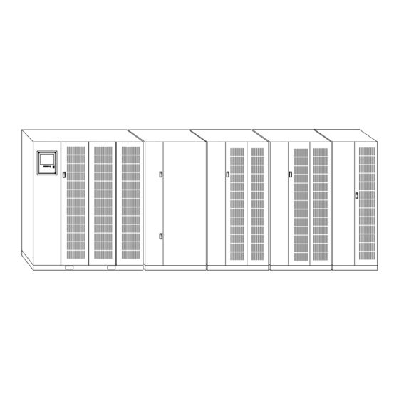
Page 10: Figure 2-1. Typical Powerware 9315 Ups System
Powerware 9315 UPS system. Cabinet Figure 2-1. Typical Powerware 9315 UPS System Each cabinet of the UPS system is shipped separately. As shown in Figure 2-1, you can combine a UPS with any of the options described in this manual to meet your system needs. -
Page 11: Looking Inside The Ups
2.3 Looking Inside the UPS The Powerware 9315 is a continuous-duty, solid-state UPS that supports the following equipment: process control, data processing, telecommunications/PBX, research, and medical. The Powerware 9315 maintains power to the critical loads during commercial electrical power brownout, blackout, overvoltage, undervoltage, and out-of-tolerance frequency conditions. -
Page 12: Ups Standard Features
2.4 UPS Standard Features The UPS has many standard features that provide cost-effective and consistently reliable power protection: 2.4.1 Monitor Panel The Monitor Panel on the front of the UPS contains an LCD screen to display the current status of the UPS. You can view a statistical history and log of UPS events and display a real-time graphic representation of power flowing through the UPS components. -
Page 13: Emergency Load Off
Several battery capacities are available. The UPS battery cabinets can be paralleled; you can increase the battery backup time by adding battery cabinets to your UPS system. The Powerware 9315 can support up to four battery cabinets. 2.5.2 External Battery Disconnect An optional DC circuit breaker, enclosed in a wall-mounted box adjacent to the UPS, provides a manual means of disconnecting a battery that is located remotely from the UPS. -
Page 14: Power Distribution Module (Lv Models Only)
2.5.3 Power Distribution Module (LV models only) An optional output Power Distribution Module (PDM) is available to distribute the output power of the UPS to the critical load. The PDM cabinet has one or two panels, each containing up to 42 poles for breaker switches. This arrangement provides flexibility for the needs of your facility. -
Page 15: Output Transformer
2.5.9 Output Transformer An optional 480/208 Vac output auto transformer provides a 208 Vac output for applications that require 208 Vac. The transformer is contained in a separate cabinet. 2.5.10 Modem An optional modem is available for use with the UPS Remote Notification feature described in “Remote Notification”... -
Page 16: Symbols, Controls, And Indicators
2.6 Symbols, Controls, and Indicators These symbols may appear on the UPS system or on labels inside the UPS. They are accepted by most international safety agents. Everyone in your organization who works with your UPS should understand the meaning of these symbols: ON - The principal power switch is in the On position. -
Page 17: Understanding Ups Operation
Chapter 3 Understanding UPS Operation The UPS functions automatically to supply AC electrical power to the critical load. The UPS always operates in one of three modes: In Normal mode, the critical load is supplied by the inverter, which derives its power from rectified utility AC power. -
Page 18: Figure 3-1. Path Of Current Through The Ups In Normal Mode
Bypass Input Rectifier Input Path of electrical power Figure 3-1. Path of Current Through the UPS in Normal Mode If the utility AC power is interrupted or is out of specification, the UPS automatically switches to Battery mode to support the critical load with no interruption. When utility power returns, the UPS returns to Normal mode. -
Page 19: Bypass Mode
3.2 Bypass Mode The UPS automatically switches to Bypass mode if it detects an overload, load fault, or internal failure. The bypass source supplies the commercial AC power to the load directly. The critical load is not protected while the UPS is in Bypass mode. Figure 3-2 shows the path of electrical power through the UPS system when the UPS is operating in Bypass mode. -
Page 20: Battery Mode
3.3 Battery Mode The UPS transfers to Battery mode automatically if a utility power outage occurs, or if the utility power does not conform to specified parameters. In Battery mode, the battery provides emergency DC power that the inverter converts to AC power. When the UPS switches to Battery mode, the alarm indications depend on the cause and condition of the battery charge. -
Page 21: Monitoring And Controlling Ups Operation
Understanding UPS Operation 3.4 Monitoring and Controlling UPS Operation After you start the UPS, no operator intervention is necessary except for periodic checks of the UPS status. Manual operation is required only during routine maintenance or service. Use the Monitor Panel and the Control Panel to monitor and control the UPS. Figure 3-4 shows the location of these two panels on the front of the UPS. - Page 22 Understanding UPS Operation This page intentionally left blank. EATON Powerware 9315 UPS (200–300 kVA) Operation Manual S 164201036 Rev F powerware.com ®...
-
Page 23: Starting And Stopping The Ups
Chapter 4 Starting and Stopping the UPS This chapter describes how to use the Control Panel to start and stop the UPS. NOTE Before starting the UPS, ensure all installation tasks are complete and a preliminary startup has been performed by authorized service personnel. The preliminary startup verifies all electrical interconnections to ensure the installation was successful and the UPS system operates properly. -
Page 24: To Place The Ups In Normal Mode
The following describes the switches on the Control Panel (see Figure 4-1): The MODE switch is a two-position rotary switch that controls the manual transfer of the UPS to and from Bypass mode. The MODE switch is used to: - Place the critical load in Bypass mode when the UPS is operating in Normal mode and the bypass source is within acceptable limits. -
Page 25: To Shut Down The Ups From Normal Mode
When the inverter reaches full voltage, it turns on and supplies power to the critical load. It takes less than one minute for the UPS to achieve Normal mode. If a bypass source is available when you turn the START switch on, the critical load is immediately supplied by the bypass source in Bypass mode until the inverter turns on and the UPS transfers to Normal mode. - Page 26 Starting and Stopping the UPS This page intentionally left blank. EATON Powerware 9315 UPS (200–300 kVA) Operation Manual S 164201036 Rev F powerware.com ®...
-
Page 27: Using The Monitor Panel
Chapter 5 Using the Monitor Panel This chapter describes the Monitor Panel and how to monitor and control UPS operation. The Monitor Panel is a black rectangular area on the front of the UPS (see Figure 5-1). The Monitor Panel contains a flat liquid crystal display (LCD) screen (1), a horizontal row of buttons (2), a vertical column of backlit status indicators (3), and the red LOAD OFF button (4). -
Page 28: Using The Lcd Screen
Meters Events Statistics Graphics Setup Figure 5-2. Parts of the LCD Screen (Typical for Powerware 9315 300 480/480V UPS) The UPS status area contains three lines that display the current state of the UPS. The first line shows the present operational mode of the UPS. The second line shows the highest level of the current active alarms, and the third line shows any notices the UPS has posted. -
Page 29: Using The Buttons
You can use the LCD screen and the buttons beneath it to: Monitor UPS operation Look at a log of UPS events (alarms, notices, and commands) 5.2 Using the Buttons The buttons below the LCD screen are labeled with arrows indicating their functions: Press the the list of alarms and notices in the event log. -
Page 30: Reading The Status Indicators
5.5 Reading the Status Indicators The six symbols on the left side of the monitor panel are status indicators. They are backlit by colored light emitting diodes (LEDs), and they work in conjunction with the alarm horn to let you know the operating status of the UPS. Indicator Indicator Symbol... -
Page 31: Figure 5-3. System Meters Screen (Typical For Powerware 9315 300 480/480V Ups)
Meters Events Statistics Graphics Setup Figure 5-3. System Meters Screen (Typical for Powerware 9315 300 480/480V UPS) The Input area shows the phase-to-phase voltage, frequency, and phase current of the incoming utility, followed by the kVA, KW, and power factor measurements. The output area shows the same information for the power being output by the UPS. -
Page 32: Figure 5-4. Load Amps Meters Screen
System Normal Alarm: None Notice: None Battery Percent 100% Meters System Load Amps Meters Events Statistics Graphics Setup EATON Powerware Uninterruptible Power System Output Current 125% 100% Phase A Phase B Figure 5-4. Load Amps Meters Screen 9315 UPS (200–300 kVA) Operation Manual S 164201036 Rev F powerware.com ®... -
Page 33: Figure 5-5. Event History Log Screen
Select History from the Events menu to display the Event History Log. The Event History Log lists up to 400 system events in chronological order, with the most recent event listed last. The end of the log appears when you display the screen, and you must scroll upward to view older event listings. -
Page 34: Figure 5-6. Active System Events Screen
Select Active from the Events menu to display a listing of all system events that are currently active. The most recent system event is listed first. As events clear, they are removed from the Active System Events listing. Figure 5-6 shows the Active System Events screen. Alarm: On Battery Notice: None... -
Page 35: Figure 5-7. Unit Statistics Screen
Select Unit from the Statistics menu to display a listing of statistics about UPS operation. Figure 5-7 shows the Unit Statistics screen. UPS System Normal Alarm: None Notice: None Battery Percent 100% Statistics Unit Meters Events The left column shows the number of UPS incidents for the current month and total from the start date shown at the top of the screen. -
Page 36: Figure 5-8. Mimic Screen
Select Mimic from the Graphics menu to display a real-time graphical representation of the flow of current through the UPS. Figure 5-8 shows the Mimic screen. UPS System Normal Alarm: None Notice: None Battery Percent 100% Graphics Mimic Meters Events Statistics The Mimic screen shows the internal components of the UPS cabinet. -
Page 37: Figure 5-9. Time Setup Screen
Select Time from the Setup menu to display the Time Setup screen. The Time Setup screen allows you to set the internal timestamp of the UPS. The timestamp is used for logging events in the Event History Log. Figure 5-9 shows the Time Setup screen. UPS System Normal Alarm: None... -
Page 38: Figure 5-10. Setup Serial Port 1 Screen
Select Port 1 or Port 2 from the Setup menu to display one of the Port Setup screens. The Port Setup screens allow you to specify settings for the two serial communication ports on the UPS. Figure 5-10 shows the Setup Serial Port 1 screen. The X-Slot communication bay is connected internally to the DB-25 port by NOTE default;... -
Page 39: Using Features And Options
Chapter 6 Using Features and Options You can add available options and accessories to enhance the performance of your UPS system. This chapter provides detailed descriptions of some of the features and options introduced earlier in this manual. 6.1 Building Alarm Monitoring This standard feature lets you connect the UPS to your building alarms, such as smoke detectors or overtemperature alarms. -
Page 40: Figure 6-2. Summary Alarm Contacts
6.2 Summary Alarm Contacts Two summary alarm contacts are provided as a standard feature on the UPS. The alarm contacts (one notice and one alarm) are located inside the UPS on the customer interface panel (see Figure 6-2). You can specify that each contact be either normally closed (NC) or normally open (NO). If the state of the contact changes from the state you specify as normal, an alarm is issued. -
Page 41: Figure 6-3. Remote Monitor Panel
Using Features and Options 6.3 Remote Monitor Panel As an option, you can install RMPs to monitor the operation of the UPS system from virtually any location within your facility, up to 500 ft from the UPS. Each RMP contains backlit status indicators and a local horn. - Page 42 Table 6-1. Optional Monitoring Accessories Remote Monitor Panel — — — The RMP contains a local horn and the following backlit status indicators: SYSTEM NORMAL The UPS is energized (either with utility power or battery backup) and is supplying conditioned power to the critical load.
-
Page 43: Battery Cabinets
Several battery capacities are available. The UPS battery cabinets can be paralleled. With this capability, you can increase your battery backup time by adding battery cabinets to your UPS system. The Powerware 9315 can support up to four battery cabinets. -
Page 44: Figure 6-4. Relay Interface Module
6.6 Relay Interface Module An optional RIM uses relay contact closures to indicate the operating status and alarm condition of the UPS system. A maximum of two monitoring accessories (RMPs, RIMs, or SCMs) can be installed. See Table 6-1 on page 6-4 for the number of accessories permitted. -
Page 45: Figure 6-5. Supervisory Contact Module
ON BATTERY UPS ALARM ON BYPASS SHUTDOWN IMMINENT Refer to “Installing a Supervisory Contact Module” in the Powerware 9315 UPS (200–300 kVA) Installation Manual for TB2 contact configurations. EATON Powerware 9315 UPS (200–300 kVA) Operation Manual S 164201036 Rev F powerware.com ®... - Page 46 Using Features and Options This page intentionally left blank. EATON Powerware 9315 UPS (200–300 kVA) Operation Manual S 164201036 Rev F powerware.com ®...
-
Page 47: Communication
Chapter 7 Communication This chapter describes the communication features of the Powerware 9315 UPS and provides information about connecting hardware and using Terminal mode. 7.1 Locating the Communication Bays The Communication Panel inside the UPS contains a DB-9 and DB-25 serial port. The DB-9 port provides a computer interface to a Remote Monitor Panel, Relay Interface Module, or Supervisory Contact Module. -
Page 48: X-Slot Cards
Port 2 (DB-25F) RS-232 Connection (disabled by default) Figure 7-1. Location of Communication Bays on the UPS (Powerware 9315 300) 7.2 X-Slot Cards The Powerware 9315 is factory-installed with an X-Slot communication bay, and is compatible with the following cards: ConnectUPS -X Web/SNMP Card - provides remote monitoring through a Web browser interface, e-mail, and a network management system using SNMP;... -
Page 49: Lansafe Power Management Software
Modbus Card ConnectUPS SNMP Card 7.3 LanSafe Power Management Software Each Powerware 9315 UPS ships with LanSafe Power Management Software. To begin installing LanSafe software, see the instructions accompanying the Powerware Software Suite CD. LanSafe software uses an RS-232 serial link to communicate with the UPS, and it provides you with up-to-date graphics of UPS power and system data and power flow. -
Page 50: Figure 7-4. Port 2 (Db-25) Pin Assignments
Table 7-1. Pin Assignments for Port 1 (DB-9) Pin Number NOTE The X-Slot communication bay is connected internally to the DB-25 port by default; the DB-25 is disabled for other uses. Contact your Eaton service representative to purchase, install, and set up an external modem or an internal X-Slot Modem Card. EATON Powerware +24V NOT USED... - Page 51 Table 7-2. Pin Assignments for Port 2 (DB-25) Pin Number Pins 5 and 6 are tied together internally. NOTE EATON Powerware 9315 UPS (200–300 kVA) Operation Manual S 164201036 Rev F powerware.com ® Symbol Function Comments Chassis Ground Transmit Data Input to UPS Receive Data Output from UPS...
-
Page 52: Configuring The Serial Ports
7.5 Configuring the Serial Ports You must configure the port for communication using the LCD screen and buttons on the UPS Monitor Panel. Select Port 1 from the Setup menu to display one of the Setup Port screens. The screens for Port 1 and Port 2 are identical, and allow you to specify settings for the two serial communication ports. -
Page 53: Mode
Table 7-3 shows which options are available for each port. The sections that follow describe the configuration settings you can change. Table 7-3. Available Options for Each Communication Port Port 1 NOTE You should change Port 2 options only if field service has performed a wiring change. 7.5.1 Mode The operational mode of the port. -
Page 54: Data/Stop
7.5.3 Data/Stop The data size and stop bits of the equipment connected to this port. These settings determine the number of bits transmitted per ASCII character. The data size and stop bits you specify depend on the configuration of your equipment. For Port 1, the data size must be set to 8, with 1 or 2 stop bits. -
Page 55: Printing Selected Information
7.6 Terminal Mode In this mode, system events are continually logged through the serial port to the device connected to the port. Port 2 operates by default in Terminal mode. The printed log entries contain a time and date stamp and the alarm text message. Terminal mode uses this format for printing alarm entries: MMM DD An alarm message is prefixed by the word “CLEAR”... -
Page 56: Entire Log – [Ctrl]+[P]
7.6.2 Entire Log – [Ctrl]+[P] This key sequence prints the entire Event History Log of the UPS at the time the data is requested. The printout begins with the oldest alarm entry in the queue and ends with the most recent. Any alarms that occur while the Event History Log is printing are included in chronological order. -
Page 57: Meters Printout – [Ctrl]+[M]
7.6.3 Meters Printout – [Ctrl]+[M] This key sequence prints the current readings of the UPS system meters. The input area shows the phase-to-phase voltage, frequency, and phase current of the incoming utility, followed by the kVA, kW, and power factor measurements. The output area shows the same information for the power being output by the UPS. -
Page 58: System Information Printout – [Ctrl]+[A]
7.6.4 System Information Printout – [Ctrl]+[A] This key sequence prints a listing of all available serial data. This printout contains the information shown on the Event History Log and System Meters screens of the UPS (both Figure 7-6 and Figure 7-7). 7.6.5 Battery Test Printout –... -
Page 59: System Configuration Mode Main Menu
7.7 System Configuration The System Configuration mode allows you to modify special functions in your UPS. These functions include programming of building alarms, customizing building alarm messages, adjusting the nominal output voltage, and scheduling battery tests. The menus provided and their function are described in this section. 7.7.1 System Configuration Mode Main Menu When the System Configuration mode is selected with a terminal attached, you are prompted to enter the password for this mode:... -
Page 60: Enable/Disable Default Functions
7.7.3 Enable/Disable Default Functions From this menu you may either enable the building alarms for general functions or special functions such as On Generator, Go To Bypass, and Go To UPS. You may also customize the alarm messages from this menu. When 1 is selected from this menu, the following menu is displayed: Enable/Disable Default Functions 1. -
Page 61: Customize Alarm Messages
7.7.4 Customize Alarm Messages If Customize Alarm Messages is selected from the Program Building Alarm menu, you can select a custom message for a building alarm or disable a previously enabled building alarm custom message. When this entry is selected, the following menu is displayed: Customize Alarm Messages Enabled on Building Alarm Number(s) Enter Building Alarm Number:... -
Page 62: Adjust Output Voltage
7.7.5 Program Unit Name If Program Unit Name is selected from the main menu, the following is displayed: Program Unit Name Unit Name: Enter New Name or <CR> No Change: Unit Name is 45 characters maximum. NOTE The current unit name is displayed on the second line of the display and in the headers of prints from Terminal mode. -
Page 63: Battery Test Setup
7.7.8 Battery Test Setup If Battery Test Setup is selected from the main menu, the following menu is displayed: Battery Test Setup 1. Setup One-time Delayed Battery Test 2. Setup Monthly Battery Test 3. Setup Quarterly Battery Test 4. Cancel Pending Battery Test 5. -
Page 64: Modify Low Battery Time
7.7.9 Modify Low Battery Time This menu allows you to modify the low battery time warning. When selected, the following menu is displayed: Modify Low Battery Time Low Battery Time (Minutes): Enter New Low Battery Time: NOTE Low Battery Time should be no greater than 999. Press <ENTER> to return with no change. -
Page 65: Remote Notification
7.11 Remote Notification NOTE The X-Slot communication bay is connected internally to the DB-25 port by default; the DB-25 is disabled for other uses. Contact your Eaton service representative to purchase, install, and set up an external modem or an internal X-Slot Modem Card. Refer to the service documentation for detailed Remote Notification information. - Page 66 Communication This page intentionally left blank. 7-20 EATON Powerware 9315 UPS (200–300 kVA) Operation Manual S 164201036 Rev F powerware.com ®...
-
Page 67: Important Safety Instructions
Chapter 8 Maintaining the UPS System Only qualified service personnel (such as a licensed electrician) should perform the battery installation and maintenance. Risk of electrical shock. The components inside the UPS cabinet are secured to a sturdy metal frame that is supported by the UPS magnetics. -
Page 68: Performing Preventive Maintenance
Do not dispose of the battery or batteries in a fire. Batteries may explode. Proper disposal of batteries is required. Refer to your local codes for disposal requirements. Do not open or mutilate the battery or batteries. Released electrolyte is harmful to the skin and eyes. -
Page 69: Maintenance Training
Maintaining the UPS System ANNUAL maintenance - Annual preventive maintenance should be performed only by authorized service personnel familiar with maintenance and servicing of the UPS system. Contact your nearest field service office for more information about service offerings. BATTERY maintenance - Contact your nearest field service office for battery maintenance. - Page 70 Maintaining the UPS System This page intentionally left blank. EATON Powerware 9315 UPS (200–300 kVA) Operation Manual S 164201036 Rev F powerware.com ®...
-
Page 71: Product Specifications
The UPS systems are available in 50/60 Hz with various output power ratings. Smaller models within a system may be upgraded in the field to larger models: Table 9-1. Model Numbers System Powerware 9315 300 Powerware 9315 250 Powerware 9315 225 Powerware 9315 200 The following sections detail the input, output, environmental, and battery specifications for the UPS. - Page 72 Table 9-3. System Output Rectifier/Charger Capacity DC Filtering UPS Output Capacity Output Voltage Regulation Output Voltage Adjustment (Nominal +/–5%) Output Voltage Harmonic Content Output Voltage Balance Output Voltage Phase Displacement Output Transients Frequency Regulation Synchronous to Bypass Frequency Slew Rate Overload Capability Maximum Output Capability Table 9-4.
- Page 73 9315 UPS (200–300 kVA) Operation Manual S 164201036 Rev F powerware.com ® Sealed, maintenance-free, high rate discharge, lead-acid cells 480 Vdc (240 cells) for Powerware 9315 225 and Powerware 9315 300 420 Vdc (210 cells) for Powerware 9315 200 and Powerware 9315 250 2.25 Vdc per cell...
- Page 74 Product Specifications This page intentionally left blank. EATON Powerware 9315 UPS (200–300 kVA) Operation Manual S 164201036 Rev F powerware.com ®...
-
Page 75: Responding To System Events
Chapter 10 Responding to System Events When the UPS system is running in Normal mode, it continually monitors itself and the incoming utility power. In Battery or Bypass modes, the UPS may issue alarms to let you know exactly what event caused the change from Normal mode. System events can be indicated by horns, lights on the UPS, or both. - Page 76 INVERTER MESSAGES - ALARMS Over Temperature Shutdown 100% Overload Shutdown 125% Overload Shutdown Bypass Cont. (K2) Failure Bypass Cont. (K4) Failure Bypass Control Failure Inverter Cont. (K3) Failure Inverter Failure Load Off Inverter Cont. (K3) Open Bypass Cont. (K4) Failure Bypass Mode Normal Mode Keyswitch On...
- Page 77 RECTIFIER MESSAGES - ALARMS Rectifier DC Over Voltage Clear Rectifier DC Over Voltage Rectifier DC Under Voltage Clear Rectifier DC Under Voltage Rectifier Over Temperature Clear Rectifier Over Temperature Rct. Over Temperature Warning Clear Rct. Over Temp. Warning Rct. Temp. Sensor Failure Clear Rct.
- Page 78 Load Over 100% Clear Load Over 100% Overload 100% Clear Overload 100% Overload 125% Clear Overload 125% Power Supply Failure Clear Power Supply Fail. Fan Failure Clear Fan Failure 10-4 EATON Powerware MONITOR PANEL NOTICES Output AC Over Voltage Clear Output AC Over Voltage...
- Page 79 Chapter 11 Using the LOAD OFF Button Load Off is initiated by the covered, red LOAD OFF button on the Monitor Panel. This button is protected by a clear plastic shield to prevent accidental activation. In an emergency, you can press this button to instantaneously open the input breaker and interrupt UPS output.
-
Page 80: Resetting The Ups System After Load Off
11.2 Resetting the UPS System after Load Off Do not attempt to restart the system after Load Off until the cause of the emergency has been identified and cleared. The Load Off PUSH TO RESET button is a small white button on the UPS Control Panel. The PUSH TO RESET button pops out and the CB1 switch trips when the LOAD OFF button on the Monitor Panel is activated. -
Page 81: Warranty
PRODUCTS ® WARRANTOR: The warrantor for the limited warranties set forth herein is Eaton Electrical Inc., a Delaware Corporation (“Eaton”). LIMITED WARRANTY: This limited warranty (this “Warranty”) applies only to the original end-user (the “End-User”) of the Powerware Three-Phase UPS Products (the “Product”) and cannot be transferred. This Warranty applies even in the event that the Product is initially sold by Eaton for resale to an End-User. - Page 82 Warranty This page intentionally left blank. EATON Powerware 9315 UPS (200–300 kVA) Operation Manual S 164201036 Rev F powerware.com ®...
- Page 84 *164201036F* 164201036 F...
Need help?
Do you have a question about the Powerware 9315 and is the answer not in the manual?
Questions and answers