Table of Contents
Advertisement
Advertisement
Table of Contents

Related Manuals for Eaton Powerware 9120


Summary of Contents for Eaton Powerware 9120
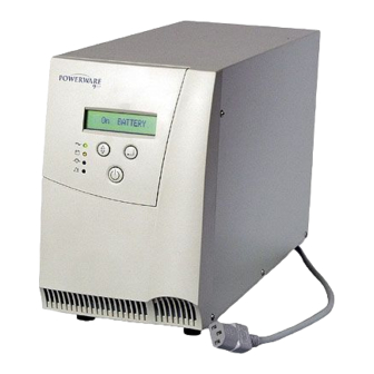
- Page 1 POWERWARE 9120 ® User’s Guide 700 VA - 3000VA www.powerware.com...
- Page 2 POWERWARE 9120 ® 700, 1000, 1500, 2000 & 3000VA User’s Guide Important Notice The UPS ground (earth) conductor carries leakage current from the loads in addition to any leakage current generated by the UPS. This UPS generates no more than 1 mA of current.
-
Page 3: If You Have A Question
Eaton Powerware may tell you the UPS must be returned. If this happens, we will give you a Return Authorisation (RA) number. When you return a Powerware 9120 to the factory for any reason, please use the original packing material in which your unit was shipped to you. -
Page 4: Table Of Contents
Table of Contents Safety Instructions ........2 UPS Features ........3 Quick Startup . -
Page 5: Safety Instructions
UPS and batteries. Whenever the Powerware 9120 is “On,” there may be dangerous voltage present at the unit’s outlets. This is true because the unit’s battery supplies power even if the unit is not plugged into the wall outlet. -
Page 6: Ups Features
UPS Features The Powerware 9120 provides protection against power problems, including power outages, brownouts, and sudden increases in power. It also provides spike suppression and line noise fil- tering to protect your equipment. Front panel LEDs and an audible alarm keep you aware of the unit’s status. - Page 7 USB Port Communication Port M O D EL N O . : 06250700A I N PU T : 208/ 220/ 230V/ 240V, I N PU T : 24V, 25A O U TPU T U SE W I TH : 2BAT 700 ASSEM BLED I N TAI W AN Inverter Shutdown Connector...
- Page 8 USB Port Communication Port Input Connector IEC C14 10A Fig 4. 2000VA Rear Panel Communication Slot Network Surge Suppression Battery Connector Inverter Shutdown Connector Load Segment 2 2 x Australian 10A Load Segment 1 3 x Australian 10A USB Port Communication Port Input Connector IEC C20 16A...
-
Page 9: Quick Startup
2.0 Quick Startup Your Powerware 9120 UPS has a removable power cord. Connect the power cord to the back of the unit and plug the UPS into a wall outlet. The LCD backlight will illuminate and the fan will run, but no output power is available. -
Page 10: Operation
3.0 Operation This section describes: • The UPS front panel • Turning the UPS on and off • Starting the UPS on battery UPS Front Panel The UPS front panel indicates the UPS status and also identifies potential power problems. Figure 6 shows the UPS front panel indicators and controls. -
Page 11: Turning The Ups On
Turning the UPS On After the UPS is connected to a power source, the fan turns on and the UPS enters Standby mode. To turn on the UPS, press and hold the button until you hear the UPS beep (approximately one second). -
Page 12: Configuration
Configuration This section describes how to reconfigure options using the Configuration mode, including: input and output voltage and frequency, site wiring fault, and silencing the alarm. NOTE The UPS has been factory-configured with default settings appropriate for most installations. User configuration is not normally required. Configuration Mode The control buttons ( front panel and Table 1 explains the corresponding options. - Page 13 Table 1. Configuration Mode Parameters Parameter LCD Message Output Voltage Setting O/P V Setting Input Voltage Tolerance I/P Bypass Set Input Frequency I/P F Setting High-Efficiency Mode HE Mode Setting Free Run Mode Free Run Mode Alarm Silence Alarm Silence Description To change the output voltage •...
- Page 14 Table 1. Configuration Mode Parameters (cont.) Parameter LCD Message Manual Battery Test Manual Bat Test Manual UPS Test Manual UPS Test Site Wiring Fault Alarm Site Fault Set Modem Support Modem Support Number of Extended Bat Pack Num Set Battery Modules Communications Lock- COM Control Cmds...
-
Page 15: Additional Ups Features
Optional SOLA communication cards Inverter Shutdown The Powerware 9120 includes a port that allows the UPS inverter to be switched off. This feature is designed to be used with Eaton powerware External Maintenance Bypass Switches. Refer to the instructions provided with the switch for further information. -
Page 16: Communication Port
Refer to the power management software instructions for using the USB port. Communication Slot The Powerware 9120 UPS has a communication slot that allows quick installation of the optional SNMP/Web adapter or future communication interfaces. These interface adapters extend the capabilities of the Powerware 9120 system to provide compatibility with network and remote moni- toring/management systems. -
Page 17: Relay Card
Relay Card This interface provides true relay contact output to peripheral devices. Outputs are user-selectable as normally open or normally closed. Table 2. Relay Card (AS/400) Pin Assignment Pin Number Signal Name Line OK Line Failure Battery Normal Battery Low UPS Alarm UPS On/OK UPS Online/Inverter... -
Page 18: Replacing The Batteries
7.0 Replacing the Batteries The Powerware 9120 batteries are user-replaceable and can be replaced while the Powerware 9120 has AC input applied and powers the loads. This means that, if necessary, you can replace the batteries while the UPS is running. Before you replace the batteries, make sure that you read the safety information below. -
Page 19: How To Replace Internal Batteries
How to Replace Internal Batteries Use the following steps to replace the internal batteries: Using caution not to put stress on the LCD display cable, pull the top of the front panel forward. Release the spring latches at the bottom of the front panel and remove it, placing it to the side of the UPS. -
Page 20: Specifications
8.0 Specifications Eaton Powerware reserves the right to change specifications without prior notice. This section provides the following specifications for the Powerware 9120 models: • Electrical input and output • Environmental and safety • Weights and dimensions • Battery Table 4. Electrical Input... - Page 21 Table 6. Environmental and Safety Operating Temperature Storage Temperature Relative Humidity Operating Altitude Audible Noise Safety Conformance Table 7. Weights and Dimensions UPS 240V Models Dimensions (WxDxH) 700-1000 VA: 15.8 x 41.2 x 24.3 cm 1500 VA: 17.0 x 44.4 x 27.5 cm 2000-3000 VA: 21.7 x 47.2 x 36.1 cm Weight 700 VA: 12.6 kg...
- Page 22 Table 8. Battery Configuration Type Charging Table 9. Battery Run Times (in Minutes) Number of Batteries 700 VA UPS Internal Batteries NOTE Battery times are approximate and vary depending on the load configuration and battery charge. 700 VA: (2) 12V, 9 Ah internal batteries; 24 Vdc 1000 VA: (3) 12V, 9 Ah internal batteries;...
-
Page 23: Troubleshooting
Troubleshooting If you have a question or problem, the troubleshooting table may help (See Table 10). If you need assistance, phone Eaton Powerware Service or your local Eaton Powerware office. Please have the model number and serial number (located on the rear of the unit) available. If the unit must be returned, Eaton Powerware will give you a Return Authorisation (RA) number. - Page 24 Table 10. Troubleshooting LCD Message or Condition UPS does not turn on. LCD panel is blank. UPS does not provide the expected backup time The UPS operates normally, but some or all of the protected equipment is not on. On-Battery 1 beep every 5 seconds.
- Page 25 Table 10. Troubleshooting (cont.) LCD Message or Condition Low Battery 2 beeps every 5 seconds. Replace Battery 3 beeps every 5 seconds. Low Charge 3 beeps every 5 minutes. Output Overload 2 beeps per second. Battery Overload 2 beeps per second. Site Fault 1 beep per second.
- Page 26 Table 10. Troubleshooting (cont.) LCD Message or Condition Over-Charge Constant beep. Charger Failure Output Short Constant beep. High Output Voltage Constant beep. Low Output Voltage Constant beep. High DC Bus 2 beeps per second. Possible Cause Batteries are over-charged. Charger has failed. Output short circuit.
-
Page 27: Warranty
10. Warranty WARRANTY Information This Warranty is subject to Eaton Power Quality Pty Ltd (EPQ) standard Conditions of Sale, which govern all sales of products by Eaton Power Quality Pty Ltd. EPQ products, in general, are warranted against failure due to faulty materials and/or workmanship for a period of two years from despatch date (ex EPQ store) as per invoice. - Page 28 High grade batteries, designed for Uninterruptible Power Supply (UPS) applications, are supplied by EPQ for use with EPQ UPS equipment. These batteries have a finite life expectancy depending on a number of variables, including rate of discharge, depth of discharge, operating temperature, etc.
-
Page 31: Eaton Powerware Australia/New Zealand Offices
Eaton Powerware Australia/New Zealand Offices Head Office - Sydney Eaton Power Quality Pty Ltd 10 Kent Road Mascot NSW 2020 Phone: 61-2-9693 9366 Fax: 61-2-8338 1159 National Service and Repair Centre Web Site: www.powerware.com.au Customer Service Offices Adelaide PO Box 481, Marlestone Business Centre SA 5033 Phone: 08-8347-3622 Fax: 08-8445-6328... - Page 32 You have purchased a UPS that will provide you with many years of service, protecting your equipment from surges, sags, and blackouts. This product incorporates the highest quality standards in engineering, manufacturing and testing, and carries a 2 year warranty against defects in material and workmanship. This product is backed by over 60 years of pride and integrity.
Need help?
Do you have a question about the Powerware 9120 and is the answer not in the manual?
Questions and answers