Table of Contents
Advertisement
Advertisement
Table of Contents

Related Manuals for Asus A8N-SLI DLX


Summary of Contents for Asus A8N-SLI DLX
- Page 1 A8N-SLI Deluxe...
- Page 2 Product warranty or service will not be extended if: (1) the product is repaired, modified or altered, unless such repair, modification of alteration is authorized in writing by ASUS; or (2) the serial number of the product is defaced or missing.
-
Page 3: Table Of Contents
Welcome! ................1-1 Package contents ..............1-1 Special features ..............1-2 1.3.1 Product highlights ........... 1-2 1.3.2 ASUS Proactive features ........1-5 1.3.3 Innovative ASUS features ........1-6 Chapter 2: Hardware information Chapter 2: Hardware information Chapter 2: Hardware information... - Page 4 4.1.2 Updating the BIOS ..........4-2 4.1.3 Saving the current BIOS file ........4-4 4.1.4 ASUS CrashFree BIOS 2 utility ........ 4-5 4.1.5 ASUS EZ Flash utility ..........4-7 4.1.6 ASUS Update utility ..........4-8 BIOS setup program ............4-11 4.2.1...
- Page 5 Contents Main menu ................4-15 4.3.1 System Time ............4-15 4.3.2 System Date ............4-15 4.3.3 Language .............. 4-15 4.3.4 Legacy Diskette A ..........4-15 4.3.5 Primary and Secondary IDE Master/Slave ..... 4-16 4.3.5 First, Second, Third, Fourth SATA Master .... 4-18 4.3.7 HDD SMART Monitoring ........
- Page 6 Chapter 6: SLI™ technology support Chapter 6: SLI™ technology support Overview ................6-1 Dual graphics card setup ............6-2 6.2.1 Setting the ASUS EZ selector card ......6-2 6.2.2 Installing SLI-ready graphics cards ......6-4 6.2.3 Setting the SLI mode in BIOS ......... 6-8 6.2.4...
-
Page 7: Notices
Notices Federal Communications Commission Statement Federal Communications Commission Statement Federal Communications Commission Statement Federal Communications Commission Statement Federal Communications Commission Statement This device complies with Part 15 of the FCC Rules. Operation is subject to the following two conditions: • This device may not cause harmful interference, and •... -
Page 8: Safety Information
Safety information Electrical safety Electrical safety Electrical safety Electrical safety Electrical safety • To prevent electrical shock hazard, disconnect the power cable from the electrical outlet before relocating the system. • When adding or removing devices to or from the system, ensure that the power cables for the devices are unplugged before the signal cables are connected. -
Page 9: About This Guide
About this guide This user guide contains the information you need when installing and configuring the motherboard. How this guide is organized How this guide is organized How this guide is organized How this guide is organized How this guide is organized This manual contains the following parts: •... -
Page 10: Where To Find More Information
A S U S w e b s i t e s A S U S w e b s i t e s The ASUS website provides updated information on ASUS hardware and software products. Refer to the ASUS contact information. -
Page 11: A8N-Sli Deluxe Specifications Summary
- 1 x PCI Express x1 card on second slot (black) ASUS EZ Selector ASUS EZ Plug™ ASUS SLI Warning LED ASUS PEG Link for dual PCI Express graphics cards ASUS Two-slot thermal design NVIDIA ® nForce™ 4 SLI chipset supports:... - Page 12 A I O v e r c l o c k i n g A I O v e r c l o c k i n g ASUS AI Overclocking (Intelligent CPU frequency tuner) ASUS PEG Link for single/dual graphics card Fixed PCI Express/PCI/SATA frequencies ASUS C.P.R.
- Page 13 ASUS PC Probe ASUS Live Update utility ASUS Cool’n’Quiet! utility Anti-virus utility (OEM version) NVIDIA ®...
- Page 14 x i v x i v x i v x i v x i v...
-
Page 15: Chapter 1: Product Introduction
This chapter describes the motherboard features and the new technologies it supports. Product introduction... - Page 16 Chapter summary Welcome! ................1-1 Package contents ..............1-1 Special features ..............1-2 ASUS A8N-SLI Deluxe ASUS A8N-SLI Deluxe ASUS A8N-SLI Deluxe ASUS A8N-SLI Deluxe ASUS A8N-SLI Deluxe...
-
Page 17: Welcome
A 8 N - S L I D e l u x e m o t h e r b o a r d ! The motherboard delivers a host of new features and latest technologies, making it another standout in the long line of ASUS quality motherboards! Before you start installing the motherboard, and hardware devices on it, check the items in your package with the list below. -
Page 18: Special Features
Special features 1.3.1 1.3.1 Product highlights Product highlights 1.3.1 1.3.1 1.3.1 Product highlights Product highlights Product highlights Latest processor technology Latest processor technology Latest processor technology Latest processor technology Latest processor technology The AMD Athlon™ 64FX and Athlon™ 64 desktop processors are based on AMD’s 64-bit and 32-bit architecture, which represents the landmark introduction of the industry’s first x86-64 technology. - Page 19 HyperTransport™ Technology HyperTransport™ Technology HyperTransport™ Technology HyperTransport™ Technology HyperTransport™ Technology HyperTransport™ Technology is a high-speed, low latency, point-to-point link designed to increase the communication speed between integrated circuits in computers, networking and telecommunicatons equipment up to 48 times faster than other existing technologies. Dual Channel DDR memory support Dual Channel DDR memory support Dual Channel DDR memory support...
- Page 20 S/PDIF digital sound ready S/PDIF digital sound ready S/PDIF digital sound ready S/PDIF digital sound ready S/PDIF digital sound ready The motherboard supports the S/PDIF Out function through the S/PDIF interfaces on the rear panel. The S/PDIF technology turns your computer into a high-end entertainment system with digital connectivity to powerful audio and speaker systems.
-
Page 21: Asus Proactive Features
AI NOS™ (Non-Delay Overclocking System) AI NOS™ (Non-Delay Overclocking System) AI NOS™ (Non-Delay Overclocking System) ASUS Non-delay Overclocking System™ (NOS) is a technology that auto-detects the CPU loading and dynamically overclocks the CPU speed only when needed. See page 4-29 for details. -
Page 22: Innovative Asus Features
ASUS EZ Plug™ ASUS EZ Plug™ ASUS EZ Plug™ This patented ASUS technology is a 4-pin auxiliary +12V connector that is designed to maintain the voltage integrity of your system. This plug guarantees adequate supply of power to the motherboard and other installed peripherals. - Page 23 ASUS Instant Music This unique feature allows you to playback audio files even without booting the system to Windows™. Just press the ASUS Instant Music special function keys and enjoy the music! See pages 4-34. A S U S A 8 N - S L I D e l u x e...
- Page 24 1 - 8 1 - 8 1 - 8 C h a p t e r 1 : P r o d u c t i n t r o d u c t i o n C h a p t e r 1 : P r o d u c t i n t r o d u c t i o n C h a p t e r 1 : P r o d u c t i n t r o d u c t i o n 1 - 8 1 - 8...
-
Page 25: Chapter 2: Hardware Information
This chapter lists the hardware setup procedures that you have to perform when installing system components. It includes description of the jumpers and connectors on the motherboard. Hardware information... - Page 26 Before you proceed .............. 2-1 Motherboard overview ............2-2 Central Processing Unit (CPU) ..........2-6 System memory ..............2-11 Expansion slots ..............2-14 Jumpers ................2-17 Connectors ................. 2-18 ASUS A8N-SLI Deluxe ASUS A8N-SLI Deluxe ASUS A8N-SLI Deluxe ASUS A8N-SLI Deluxe ASUS A8N-SLI Deluxe...
-
Page 27: Before You Proceed
The red warning LED lights up when you installed two graphics card but did not connect the ASUS EZ Plug™. The illustration below shows the location of the onboard LEDs. SLI_WARN_LED... -
Page 28: Motherboard Overview
Motherboard overview Before you install the motherboard, study the configuration of your chassis to ensure that the motherboard fits into it. Make sure to unplug the power cord before installing or removing the motherboard. Failure to do so can cause you physical injury and damage motherboard components. -
Page 29: Motherboard Layout
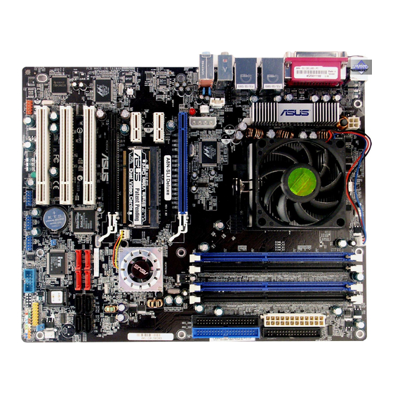
2.2.3 2.2.3 2.2.3 Motherboard layout Motherboard layout Motherboard layout 2.2.3 2.2.3 Motherboard layout Motherboard layout 24.5cm (9.6in) PS/2KBMS T: Mouse CPU_FAN CHA2_FAN B: Keyboard ATX12V SPDIF_O SPDIF_O2 LAN2_USB12 LAN1_USB34 Top:Rear Speaker Out Center: Side Speaker Out Below: Center/Subwoofer Marvell Top:Line In 88E1111 Center:Line Out Bottom:Mic In... -
Page 30: Layout Contents
2.2.4 2.2.4 2.2.4 2.2.4 2.2.4 Layout Contents Layout Contents Layout Contents Layout Contents Layout Contents S l o t s S l o t s P a g e P a g e S l o t s S l o t s S l o t s P a g e P a g e... - Page 31 20. IEEE 1394a connector (10-1 pin IE1394_1) 2-27 21. Front panel audio connector (10-1 pin FP_AUDIO) 2-28 22. ASUS EZ selector card connector (144-pin SLI_CON) 2-28 22. System panel connectors (20-1 pin PANEL) 2-29 - System Power LED (Green 3-pin PLED)
-
Page 32: Central Processing Unit (Cpu)
Central Processing Unit (CPU) 2.3.1 2.3.1 2.3.1 Overview Overview Overview 2.3.1 2.3.1 Overview Overview The motherboard comes with a surface mount 939-pin Zero Insertion Force (ZIF) socket designed for the AMD Athlon™ 64FX or AMD Athlon 64™ processor. The 128-bit-wide data paths of these processors can run applications faster than processors with only 32-bit or 64-bit wide data paths. - Page 33 Unlock the socket by pressing the lever sideways, then lift it up to a 90 -100 angle. S o c k e t L e v e r S o c k e t L e v e r S o c k e t L e v e r S o c k e t L e v e r S o c k e t L e v e r Make sure that the socket lever is lifted up to 90 -100 angle, otherwise...
-
Page 34: Installing The Heatsink And Fan
2.3.3 2.3.3 2.3.3 Installing the heatsink and fan Installing the heatsink and fan Installing the heatsink and fan 2.3.3 2.3.3 Installing the heatsink and fan Installing the heatsink and fan The AMD Athlon™ 64FX or AMD Athlon 64™ processor require a specially designed heatsink and fan assembly to ensure optimum thermal condition and performance. - Page 35 Attach one end of the retention bracket to the retention module base. Align the other end of the retention bracket (near the retention bracket lock) to the retention module base. A clicking sound denotes that the retention bracket is in place. Make sure that the fan and heatsink assembly perfectly fits the retention mechanism...
- Page 36 When the fan and heatsink assembly is in place, connect the CPU fan cable to the connector on the motherboard labeled CPU_FAN. CPU_FAN A8N-SLI DELUXE ® A8N-SLI DELUXE CPU fan connector Do not forget to connect the CPU fan connector! Hardware monitoring errors can occur if you fail to plug this connector.
-
Page 37: System Memory
System memory 2.4.1 2.4.1 Overview Overview 2.4.1 2.4.1 2.4.1 Overview Overview Overview The motherboard comes with four 184-pin Double Data Rate (DDR) Dual Inline Memory Modules (DIMM) sockets. The following figure illustrates the location of the sockets: A8N-SLI DELUXE ® A8N-SLI DELUXE 184-pin DDR DIMM sockets C h a n n e l C h a n n e l... -
Page 38: Memory Configuration
C C C C C - support for 4 modules inserted into the blue and black slots as two pairs of Dual-channel memory configuration. Visit the ASUS website (www.asus.com) for the latest DDR 400 Qualified Vendors List. 2 - 1 2... -
Page 39: Installing A Dimm
2.4.3 2.4.3 2.4.3 2.4.3 2.4.3 Installing a DIMM Installing a DIMM Installing a DIMM Installing a DIMM Installing a DIMM Make sure to unplug the power supply before adding or removing DIMMs or other system components. Failure to do so may cause severe damage to both the motherboard and the components. -
Page 40: Expansion Slots
Expansion slots In the future, you may need to install expansion cards. The following sub-sections describe the slots and the expansion cards that they support. Make sure to unplug the power cord before adding or removing expansion cards. Failure to do so may cause you physical injury and damage motherboard components. -
Page 41: Interrupt Assignments
2.5.3 2.5.3 Interrupt assignments Interrupt assignments 2.5.3 2.5.3 2.5.3 Interrupt assignments Interrupt assignments Interrupt assignments Standard interrupt assignments Standard interrupt assignments Standard interrupt assignments Standard interrupt assignments Standard interrupt assignments I R Q I R Q P r i o r i t y P r i o r i t y S t a n d a r d F u n c t i o n S t a n d a r d F u n c t i o n... -
Page 42: Pci Slots
2.5.4 2.5.4 PCI slots PCI slots 2.5.4 2.5.4 2.5.4 PCI slots PCI slots PCI slots The PCI slots support cards such as a LAN card, SCSI card, USB card, and other cards that comply with PCI specifications. The figure shows a LAN card installed on a PCI slot. -
Page 43: Jumpers
Jumpers 1 . 1 . C l e a r R T C R A M ( C L R T C ) C l e a r R T C R A M ( C L R T C ) C l e a r R T C R A M ( C L R T C ) C l e a r R T C R A M ( C L R T C ) C l e a r R T C R A M ( C L R T C ) -
Page 44: Connectors
Connectors 2.7.1 2.7.1 Rear panel connectors Rear panel connectors 2.7.1 2.7.1 2.7.1 Rear panel connectors Rear panel connectors Rear panel connectors 1 . 1 . P S / 2 m o u s e p o r t ( g r e e n ) . P S / 2 m o u s e p o r t ( g r e e n ) . - Page 45 9 . 9 . M i c r o p h o n e p o r t ( p i n k ) . M i c r o p h o n e p o r t ( p i n k ) . M i c r o p h o n e p o r t ( p i n k ) .
-
Page 46: Internal Connectors
2.7.2 2.7.2 2.7.2 2.7.2 2.7.2 Internal connectors Internal connectors Internal connectors Internal connectors Internal connectors 1 . 1 . F l o p p y d i s k d r i v e c o n n e c t o r ( 3 4 - 1 p i n F L O P P Y ) F l o p p y d i s k d r i v e c o n n e c t o r ( 3 4 - 1 p i n F L O P P Y ) F l o p p y d i s k d r i v e c o n n e c t o r ( 3 4 - 1 p i n F L O P P Y ) F l o p p y d i s k d r i v e c o n n e c t o r ( 3 4 - 1 p i n F L O P P Y ) - Page 47 3 . 3 . S e r i a l A T A c o n n e c t o r s S e r i a l A T A c o n n e c t o r s S e r i a l A T A c o n n e c t o r s S e r i a l A T A c o n n e c t o r s S e r i a l A T A c o n n e c t o r s...
- Page 48 4 . 4 . S e r i a l A T A R A I D c o n n e c t o r s ( 7 - p i n S A T A _ R A I D 1 , S e r i a l A T A R A I D c o n n e c t o r s ( 7 - p i n S A T A _ R A I D 1 , S e r i a l A T A R A I D c o n n e c t o r s ( 7 - p i n S A T A _ R A I D 1 , S e r i a l A T A R A I D c o n n e c t o r s ( 7 - p i n S A T A _ R A I D 1 ,...
- Page 49 These are not jumpers! DO NOT place jumper caps on the fan connectors! • The ASUS Q-Fan function is supported using the CPU Fan (CPU_FAN) and Chassis Fan 1 (CHA1_FAN) connectors only. • The chipset fan is synchronized with the CPU fan.
- Page 50 6 . 6 . S e r i a l p o r t c o n n e c t o r ( 1 0 - 1 p i n C O M 1 ) S e r i a l p o r t c o n n e c t o r ( 1 0 - 1 p i n C O M 1 ) S e r i a l p o r t c o n n e c t o r ( 1 0 - 1 p i n C O M 1 ) S e r i a l p o r t c o n n e c t o r ( 1 0 - 1 p i n C O M 1 ) S e r i a l p o r t c o n n e c t o r ( 1 0 - 1 p i n C O M 1 )
- Page 51 8 . 8 . A T X p o w e r c o n n e c t o r s ( 2 4 - p i n E A T X P W R 1 , A T X p o w e r c o n n e c t o r s ( 2 4 - p i n E A T X P W R 1 , A T X p o w e r c o n n e c t o r s ( 2 4 - p i n E A T X P W R 1 , A T X p o w e r c o n n e c t o r s ( 2 4 - p i n E A T X P W R 1 , A T X p o w e r c o n n e c t o r s ( 2 4 - p i n E A T X P W R 1 ,...
- Page 52 9 . 9 . I n t e r n a l a u d i o c o n n e c t o r s ( 4 - p i n C D , A U X ) I n t e r n a l a u d i o c o n n e c t o r s ( 4 - p i n C D , A U X ) I n t e r n a l a u d i o c o n n e c t o r s ( 4 - p i n C D , A U X ) I n t e r n a l a u d i o c o n n e c t o r s ( 4 - p i n C D , A U X )
- Page 53 1 1 . 1 1 . C h a s s i s i n t r u s i o n c o n n e c t o r ( 4 - 1 p i n C H A S S I S ) 1 1 .
- Page 54 A S U S E Z s e l e c t o r c a r d c o n n e c t o r ( 1 4 4 - p i n S L I _ C O N ) This connector is for the ASUS proprietary ASUS EZ selector card that allows you to set the SLI mode to either Single Video card or Dual Video cards.
-
Page 55: System Panel Connector
1 5 . 1 5 . S y s t e m p a n e l c o n n e c t o r ( 2 0 - p i n P A N E L ) S y s t e m p a n e l c o n n e c t o r ( 2 0 - p i n P A N E L ) 1 5 . - Page 56 2 - 3 0 2 - 3 0 2 - 3 0 C h a p t e r 2 : H a r d w a r e i n f o r m a t i o n C h a p t e r 2 : H a r d w a r e i n f o r m a t i o n C h a p t e r 2 : H a r d w a r e i n f o r m a t i o n 2 - 3 0...
-
Page 57: Chapter 3: Powering Up
This chapter describes the power up sequence, the vocal POST messages, and ways of shutting down the system. Powering up... - Page 58 Chapter summary Starting up for the first time ..........3-1 Powering off the computer ..........3-2 ASUS POST Reporter™ ............3-3 ASUS A8N-SLI Deluxe ASUS A8N-SLI Deluxe ASUS A8N-SLI Deluxe ASUS A8N-SLI Deluxe ASUS A8N-SLI Deluxe...
-
Page 59: Starting Up For The First Time
Starting up for the first time After making all the connections, replace the system case cover. Be sure that all switches are off. Connect the power cord to the power connector at the back of the system chassis. Connect the power cord to a power outlet that is equipped with a surge protector. -
Page 60: Powering Off The Computer
Powering off the computer 3.2.1 3.2.1 Using the OS shut down function Using the OS shut down function 3.2.1 3.2.1 3.2.1 Using the OS shut down function Using the OS shut down function Using the OS shut down function If you are using Windows ®... -
Page 61: Asus Post Reporter
ASUS POST Reporter™ This motherboard includes the Winbond speech controller to support a special feature called the ASUS POST Reporter™. This feature lets you hear vocal messages during POST that alerts you of system events and boot status. In case of a boot failure, you will hear the specific cause of the problem. - Page 62 S p e e c h S p e e c h You can enable or disable the ASUS POST Reporter™ in the S p e e c h S p e e c h S p e e c h...
-
Page 63: Winbond Voice Editor
The Winbond Voice Editor software allows you to customize the vocal POST messages. You can install this application from the support CD. To avoid conflicts, do not run the Winbond Voice Editor while running the ASUS PC Probe application. Launching the Voice Editor Launching the Voice Editor... - Page 64 Y e s Y e s Y e s Y e s to confirm. The next time you boot your computer, the ASUS Post Reporter announces the messages in the selected language. 3 - 6 3 - 6 3 - 6...
- Page 65 Customizing your POST messages Customizing your POST messages Customizing your POST messages Customizing your POST messages Customizing your POST messages The Voice Editor application allows you to record your own POST messages if your language is not supported or if you wish to to replace the pre-installed wave files.
- Page 66 Select a POST event on the Voice Editor main window, then click the E d i t E d i t E d i t button. The E d i t E d i t E v e n t S o u n d E d i t o r E v e n t S o u n d E d i t o r E v e n t S o u n d E d i t o r window E v e n t S o u n d E d i t o r...
-
Page 67: Chapter 4: Bios Setup
This chapter tells how to change the system settings through the BIOS Setup menus. Detailed descriptions of the BIOS parameters are also provided. BIOS setup... - Page 68 Main menu ................4-15 Advanced menu ..............4-20 Power menu ................ 4-35 Boot menu ................4-40 Exit menu ................4-46 ASUS A8N SLI Deluxe ASUS A8N SLI Deluxe ASUS A8N SLI Deluxe ASUS A8N SLI Deluxe ASUS A8N SLI Deluxe...
-
Page 69: Managing And Updating Your Bios
Save a copy of the original motherboard BIOS file to a bootable floppy disk in case you need to restore the BIOS in the future. Copy the original motherboard BIOS using the ASUS Update or AwardBIOS Flash utilities. 4.1.1 4.1.1... -
Page 70: Updating The Bios
AwardBIOS Flash Utility. Follow these instructions to update the BIOS using this utility. 1. Download the latest BIOS file from the ASUS web site. Rename the file to A 8 N - S L I . B I N A 8 N - S L I . B I N A 8 N - S L I . - Page 71 Type the BIOS file name AwardBIOS Flash Utility for ASUS V1.01 F i l e N a m e t o F i l e N a m e t o in the F i l e N a m e t o...
-
Page 72: Saving The Current Bios File
Make sure that the floppy disk has enough disk space to save the file. To save the current BIOS file using the AwardBIOS Flash Utility: Follow steps 1 to 6 of AwardBIOS Flash Utility for ASUS V1.01 the previous section. (C) Phoenix Technologies Ltd. All Rights Reserved... -
Page 73: Asus Crashfree Bios 2 Utility
ASUS CrashFree BIOS 2 utility ASUS CrashFree BIOS 2 utility The ASUS CrashFree BIOS 2 is an auto recovery tool that allows you to restore the BIOS file when it fails or gets corrupted during the updating process. You can update a corrupted BIOS file using the motherboard support CD or the floppy disk that contains the updated BIOS file. - Page 74 Restart the system after the utility completes the updating process. The recovered BIOS may not be the latest BIOS version for this motherboard. Visit the ASUS website (www.asus.com) to download the latest BIOS file. 4 - 6...
-
Page 75: Asus Ez Flash Utility
ASUS EZ Flash utility ASUS EZ Flash utility The ASUS EZ Flash feature allows you to update the BIOS without having to go through the long process of booting from a floppy disk and using a DOS-based utility. The EZ Flash utility is built-in the BIOS chip so it is accessible by pressing <Alt>... -
Page 76: Asus Update Utility
ASUS Update utility 4.1.6 4.1.6 ASUS Update utility ASUS Update utility The ASUS Update is a utility that allows you to manage, save, and update the motherboard BIOS in Windows ® environment. The ASUS Update utility allows you to: • Save the current BIOS file •... - Page 77 Updating the BIOS through the Internet Updating the BIOS through the Internet Updating the BIOS through the Internet To update the BIOS through the Internet: Launch the ASUS Update utility from the Windows ® desktop by clicking S t a r t...
- Page 78 A S U S U p d a t e A S U S U p d a t e. The ASUS Update main window appears. U p d a t e B I O S f r o m a...
-
Page 79: Bios Setup Program
• Visit the ASUS website (www.asus.com) to download the latest BIOS file for this motherboard and . A S U S A 8 N - S L I D e l u x e... -
Page 80: Bios Menu Screen
The BIOS setup screens shown in this chapter are for reference purposes only, and may not exactly match what you see on your screen. • Visit the ASUS website (www.asus.com) to download the latest BIOS information. 4 - 1 2 4 - 1 2... -
Page 81: Legend Bar
4.2.3 4.2.3 4.2.3 Legend bar Legend bar Legend bar 4.2.3 4.2.3 Legend bar Legend bar At the bottom of the Setup screen is a legend bar. The keys in the legend bar allow you to navigate through the various setup menus. The following table lists the keys found in the legend bar with their corresponding functions. -
Page 82: General Help
Primary IDE Master [ST321122A] diskette drive A. Disabled ..[ ] Primary IDE Slave [ASUS CDS520/A] 360K , 5.25 in..[ ] Secondary IDE Master [None] 1.2M , 5.25 in..[ ] Secondary IDE Slave [None] 720K , 3.5 in. -
Page 83: Main Menu
Item Specific Help Legacy Diskette A: [1.44M, 3.5 in.] Change the day, month, year and century. Primary IDE Master [ST321122A] Primary IDE Slave [ASUS CDS520/A] Secondary IDE Master [None] Secondary IDE Slave [None] First SATA Master [None] Second SATA Slave... -
Page 84: Primary And Secondary Ide Master/Slave
4.3.5 4.3.5 4.3.5 Primary and Secondary IDE Master/Slave Primary and Secondary IDE Master/Slave Primary and Secondary IDE Master/Slave 4.3.5 4.3.5 Primary and Secondary IDE Master/Slave Primary and Secondary IDE Master/Slave While entering Setup, the BIOS automatically detects the presence of IDE devices. - Page 85 Access Mode [Auto] Access Mode [Auto] Access Mode [Auto] Access Mode [Auto] Access Mode [Auto] The default [Auto] allows automatic detection of an IDE hard disk drive. Select [CHS] for this item if you set the IDE Primary Master/Slave to [Manual].
-
Page 86: First, Second, Third, Fourth Sata Master
4.3.5 4.3.5 4.3.5 First, Second, Third, Fourth SATA Master First, Second, Third, Fourth SATA Master First, Second, Third, Fourth SATA Master 4.3.5 4.3.5 First, Second, Third, Fourth SATA Master First, Second, Third, Fourth SATA Master While entering Setup, the BIOS automatically detects the presence of Serial ATA devices. -
Page 87: Hdd Smart Monitoring
H e a d H e a d H e a d H e a d H e a d Shows the number of the hard disk read/write heads. This item is not configurable. Precomp Precomp Precomp Precomp Precomp Shows the number of precomp per track. This item is not configurable. Landing Zone Landing Zone Landing Zone... -
Page 88: Advanced Menu
Advanced menu The Advanced menu items allow you to change the settings for the CPU and other system devices. Take caution when changing the settings of the Advanced menu items. Incorrect field values can cause the system to malfunction. Phoenix-Award BIOS CMOS Setup Utility Main Advanced Power... - Page 89 DRAM Configuration DRAM Configuration DRAM Configuration DRAM Configuration DRAM Configuration The items in this sub-menu show the DRAM-related information auto-detected by the BIOS. Phoenix-Award BIOS CMOS Setup Utility Advanced DRAM Configuration Select Menu Max Memclock (MHz) [Auto] Item Specific Help 1T/2T Memory Timing [Auto] CAS# latency (Tcl)
- Page 90 Row precharge Time (Trp) [Auto] Sets the Row precharge time. Precharge to Active or Auto-Refresh of the same bank. Configuration options: [Auto] [2] [3] [4] [5] [6] Master ECC Enable [Disabled] Enables or disables the master ECC function. Configuration options: [Disabled] [Enabled] Hyper Transport Frequency [Auto] Hyper Transport Frequency [Auto] Hyper Transport Frequency [Auto]...
-
Page 91: Pcipnp
4.4.2 4.4.2 PCIPnP PCIPnP 4.4.2 4.4.2 4.4.2 PCIPnP PCIPnP PCIPnP Phoenix-Award BIOS CMOS Setup Utility Advanced Frequency/Voltage control Select Menu Plug & Play O/S [No] Item Specific Help Init Display First [PCI Slot] Resources Controlled By [Auto] x IRQ Resources PCI/VGA Palette Snoop [Disabled] F1:Help... -
Page 92: Onboard Devices Configuration
IRQ Resources IRQ Resources IRQ Resources IRQ Resources IRQ Resources This sub-menu is activated only when the R e s o u r c e s C o n t r o l l e d B y R e s o u r c e s C o n t r o l l e d B y R e s o u r c e s C o n t r o l l e d B y R e s o u r c e s C o n t r o l l e d B y R e s o u r c e s C o n t r o l l e d B y... - Page 93 IDE Function Setup IDE Function Setup IDE Function Setup IDE Function Setup IDE Function Setup This sub-menu contains IDE function-related items. Select an item then press <Enter> to edit. Phoenix-Award BIOS CMOS Setup Utility Advanced Onboard Device Configuration Select Menu OnChip IDE Channel0 [Enabled] Item Specific Help...
- Page 94 SATA2 DMA transfer [Enabled] SATA2 DMA transfer [Enabled] SATA2 DMA transfer [Enabled] SATA2 DMA transfer [Enabled] SATA2 DMA transfer [Enabled] Allows you to enable or disable the SATA2 DMA transfer access. Configuration options: [Disabled] [Enabled] IDE Prefetch Mode [Enabled] IDE Prefetch Mode [Enabled] IDE Prefetch Mode [Enabled] IDE Prefetch Mode [Enabled] IDE Prefetch Mode [Enabled]...
- Page 95 USB Configuration USB Configuration USB Configuration USB Configuration USB Configuration The items in this menu allows you to change the USB-related features. Select an item then press <Enter> to display the configuration options. Phoenix-Award BIOS CMOS Setup Utility Advanced USB Configuration Select Menu USB Controller [Enabled]...
- Page 96 OnBoard LAN2 Boot ROM [Disabled] OnBoard LAN2 Boot ROM [Disabled] OnBoard LAN2 Boot ROM [Disabled] OnBoard LAN2 Boot ROM [Disabled] OnBoard LAN2 Boot ROM [Disabled] Allows you to enable or disable the onboard LAN 2 boot ROM. This item is user-configurable only when the PCI Giga LAN item is Enabled.
-
Page 97: Jumperfree Configuration
A I N . O . S . A I N . O . S . A I N . O . S . The ASUS AI Non-delay Overclocking System feature intelligently determines the system load and automatically boost the performance for the most demanding tasks. - Page 98 The following items are user-configurable only when the Overclock Profile item is set to [Manual]. CPU Frequency [XXX] (value is auto-detected) CPU Frequency [XXX] (value is auto-detected) CPU Frequency [XXX] (value is auto-detected) CPU Frequency [XXX] (value is auto-detected) CPU Frequency [XXX] (value is auto-detected) Indicates the frequency sent by the clock generator to the system bus and PCI bus.
-
Page 99: Lan Cable Status
The following item is user-configurable only when the AI Overclocking item is set to [AI Overclock]. Overclock Options [Disable] Overclock Options [Disable] Overclock Options [Disable] Overclock Options [Disable] Overclock Options [Disable] Allows you to set the oveclocking options. Configuration options: [Disable] [Overclock 3%] [Overclock 5%] [Overclock 8%] [Overclock 10%] The following item is user-configurable only when the AI Overclocking item is set to [AI N.O.S.]. -
Page 100: Peg Link Mode
4.4.6 4.4.6 PEG Link Mode PEG Link Mode 4.4.6 4.4.6 4.4.6 PEG Link Mode PEG Link Mode PEG Link Mode Phoenix-Award BIOS CMOS Setup Utility Advanced JumperFree Configuration Select Menu PEG Link Mode [Auto] Item Specific Help PEG Root Control [Auto] PEG Buffer Length [Auto]... -
Page 101: Speech Configuration
Speech IC Reporter [Enabled] Speech IC Reporter [Enabled] Speech IC Reporter [Enabled] Allows you to enable or disable the ASUS Speech POST Reporter™ feature. Configuration options: [Disabled] [Enabled] The following items appear only when Speech POST Reporter is set to Enabled. -
Page 102: Instant Music
Instant Music [Disabled] Instant Music [Disabled] Instant Music [Disabled] Instant Music [Disabled] Allows you to enable or disable the ASUS Instant Music feature. Configuration options: [Disabled] [Enabled] Enabling Instant Music automatically disables the PS/2 keyboard power up feature. Instant Music CD-ROM Drive [Primary Master]... -
Page 103: Power Menu
Power menu The Power menu items allow you to change the settings for the Advanced Configuration and Power Interface (ACPI) and the Advanced Power Management (APM). Select an item then press <Enter> to display the configuration options. Phoenix-Award BIOS CMOS Setup Utility Main Advanced Power... -
Page 104: Apm Configuration
4.5.3 4.5.3 4.5.3 APM Configuration APM Configuration APM Configuration 4.5.3 4.5.3 APM Configuration APM Configuration Phoenix-Award BIOS CMOS Setup Utility Power APM Configuration Select Menu Restore on AC Power Loss [Disabled] Item Specific Help PWR Button < 4 secs [Instant Off] Power On By PCI Devices [Disabled] Press [ENTER] to... - Page 105 Power On By RTC Alarm [Disabled] Power On By RTC Alarm [Disabled] Power On By RTC Alarm [Disabled] Power On By RTC Alarm [Disabled] Power On By RTC Alarm [Disabled] Allows you to enable or disable RTC to generate a wake event. When this item is set to Enabled, the items Date of Month Alarm and Time (hh:mm:ss) Alarm items become user-configurable with set values.
-
Page 106: Hardware Monitor
4.5.4 4.5.4 4.5.4 Hardware Monitor Hardware Monitor Hardware Monitor 4.5.4 4.5.4 Hardware Monitor Hardware Monitor The items in this sub-menu displays the hardware monitor values automatically detected by the BIOS. It also allows you to change CPU Q-Fan feature-related parameters. Select an item then press <Enter> to display the configuration options. - Page 107 Q-Fan1 Stop Temperature Q-Fan1 Stop Temperature Q-Fan1 Stop Temperature Q-Fan1 Stop Temperature Q-Fan1 Stop Temperature Allows you to set the temperature threshold before the CPU fan stops. Configuration options: [16ºC] [18ºC] [20ºC] [22ºC] Q-Fan1 Start Temperature Q-Fan1 Start Temperature Q-Fan1 Start Temperature Q-Fan1 Start Temperature Q-Fan1 Start Temperature Allows you to set the temperature that when detected starts the CPU fan.
-
Page 108: Boot Menu
Boot menu The Boot menu items allow you to change the system boot options. Select an item then press <Enter> to display the sub-menu. Phoenix-Award BIOS CMOS Setup Utility Main Advanced Power Boot Exit Boot Device Priority Select Menu Removable Drives Hard Disk Drives Item Specific Help CDROM Drives... -
Page 109: Removable Drives
4.6.2 4.6.2 Removable Drives Removable Drives 4.6.2 4.6.2 4.6.2 Removable Drives Removable Drives Removable Drives Phoenix-Award BIOS CMOS Setup Utility Boot Removable Drives Select Menu 1. Floppy Disks Item Specific Help Use < > or < > to select a device, then press <+>... -
Page 110: Cdrom Drives
4.6.4 4.6.4 4.6.4 4.6.4 4.6.4 CDROM Drives CDROM Drives CDROM Drives CDROM Drives CDROM Drives Phoenix-Award BIOS CMOS Setup Utility Boot CDROM Drives Select Menu 1. 1st Slave: XXXXXXXXX Item Specific Help Use < > or < > to select a device, then press <+>... - Page 111 • Make sure that the above item is set to [Enabled] if you want to use the ASUS MyLogo2™ feature. • See section “5.4.1 ASUS MyLogo2™” for details. Halt On [All Errors] Halt On [All Errors] Halt On [All Errors]...
-
Page 112: Security
4.6.6 4.6.6 4.6.6 4.6.6 4.6.6 Security Security Security Security Security Phoenix-Award BIOS CMOS Setup Utility Boot Boot Settings Configuration Select Menu Supervisor Password Clear Item Specific Help User Password Clear Password Check [Setup] Supervisor password controls full access, <Enter> to change password. - Page 113 A n o t e a b o u t p a s s w o r d s A n o t e a b o u t p a s s w o r d s A n o t e a b o u t p a s s w o r d s A n o t e a b o u t p a s s w o r d s A n o t e a b o u t p a s s w o r d s The Supervisor password is required to enter the BIOS Setup program...
-
Page 114: Exit Menu
Exit menu The Exit menu items allow you to load the optimal or failsafe default values for the BIOS items, and save or discard your changes to the BIOS items. Phoenix-Award BIOS CMOS Setup Utility Main Advanced Power Boot Exit Select Menu Exit &... - Page 115 Load Setup Defaults Load Setup Defaults Load Setup Defaults Load Setup Defaults Load Setup Defaults This option allows you to load the default values for each of the parameters on the Setup menus. When you select this option or if you Y e s Y e s press <F5>, a confirmation window appears.
- Page 116 4 - 4 8 4 - 4 8 C h a p t e r 4 : B I O S s e t u p C h a p t e r 4 : B I O S s e t u p 4 - 4 8 4 - 4 8 4 - 4 8...
-
Page 117: Chapter 5: Software Support
This chapter describes the contents of the support CD that comes with the motherboard package. Software support... - Page 118 Support CD information ............5-1 Software information ............5-9 RAID configurations ............5-21 Creating a RAID driver disk ..........5-40 Cool ‘n’ Quiet!™ Technology ..........5-41 ASUS A8N-SLI Deluxe ASUS A8N-SLI Deluxe ASUS A8N-SLI Deluxe ASUS A8N-SLI Deluxe ASUS A8N-SLI Deluxe...
-
Page 119: Installing An Operating System
The support CD that came with the motherboard package contains the drivers, software applications, and utilities that you can install to avail all motherboard features. The contents of the support CD are subject to change at any time without notice. Visit the ASUS website(www.asus.com) for updates. 5.2.1 5.2.1 5.2.1... -
Page 120: Drivers Menu
5.2.2 5.2.2 5.2.2 Drivers menu Drivers menu Drivers menu 5.2.2 5.2.2 Drivers menu Drivers menu The drivers menu shows the available device drivers if the system detects installed devices. Install the necessary drivers to activate the devices. Nvidia Chipset Driver Program Nvidia Chipset Driver Program Nvidia Chipset Driver Program Nvidia Chipset Driver Program... -
Page 121: Utilities Menu
ASUS Update ASUS Update ASUS Update Allows you to download the latest version of the BIOS from the ASUS website. Before using the ASUS Update, make sure that you have an Internet connection so you can connect to the ASUS website. - Page 122 ASUS AI Booster ASUS AI Booster ASUS AI Booster ASUS AI Booster ASUS AI Booster The ASUS AI Booster application allows you to overclock the CPU speed in a Windows ® environment. Microsoft DirectX Microsoft DirectX Microsoft DirectX Microsoft DirectX...
-
Page 123: Manuals Menu
5.2.4 5.2.4 5.2.4 5.2.4 5.2.4 Manuals menu Manuals menu Manuals menu Manuals menu Manuals menu The Manuals menu contains a list of supplementary user manuals. Click an item to open the folder of the user manual. • Most user manual files are in Portable Document Format (PDF). ®... -
Page 124: Asus Contact Information
C o n t a c t C o n t a c t C o n t a c t tab to display the ASUS contact information. You can C o n t a c t also find this information on the inside front cover of this user guide. - Page 125 Technical support Form Technical support Form Displays the ASUS Technical Support Request Form that you have to fill out when requesting technical support. A S U S A 8 N - S L I D e l u x e...
- Page 126 Filelist Filelist Filelist Filelist Filelist Displays the contents of the support CD and a brief description of each in text format. 5 - 8 5 - 8 5 - 8 C h a p t e r 5 : S o f t w a r e s u p p o r t C h a p t e r 5 : S o f t w a r e s u p p o r t C h a p t e r 5 : S o f t w a r e s u p p o r t 5 - 8...
-
Page 127: Software Information
ASUS MyLogo2™ ASUS MyLogo2™ ASUS MyLogo2™ The ASUS MyLogo2™ utility lets you customize the boot logo. The boot logo is the image that appears on screen during the Power-On Self-Tests (POST). The ASUS MyLogo2™ is automatically installed when you install the A S U S U p d a t e A S U S U p d a t e utility from the support CD. - Page 128 R a t i o box. R a t i o When the screen returns to the ASUS Update utility, flash the original BIOS to load the new boot logo. 10. After flashing the BIOS, restart the computer to display the new boot logo during POST.
-
Page 129: Ai Net 2
5.4.3 5.4.3 5.4.3 5.4.3 5.4.3 AI NET 2 AI NET 2 AI NET 2 AI NET 2 AI NET 2 The Marvell ® Virtual Cable Tester™ (VCT) is a cable diagnostic utility that reports LAN cable faults and shorts using the Time Domain Reflectometry (TDR) technology. -
Page 130: Audio Configurations
5.4.4 5.4.4 Audio configurations Audio configurations 5.4.4 5.4.4 5.4.4 Audio configurations Audio configurations Audio configurations The Realtek ® ALC850 AC ‘97 audio CODEC provides 8-channel audio capability to deliver the ultimate audio experience on your PC. The software provides Jack-Sensing function (Line-In, Line-Out, Mic-In), S/PDIF out support and interrupt capability. - Page 131 To set the sound effect options: From the Realtek Audio Control Panel, click the S o u n d E f f e c t S o u n d E f f e c t S o u n d E f f e c t S o u n d E f f e c t S o u n d E f f e c t button.
- Page 132 Speaker Configuration Speaker Configuration Speaker Configuration Speaker Configuration Speaker Configuration This option allows you to set your speaker configuration. To set the speaker configuration: S p e a k e r S p e a k e r From the Realtek Audio Control Panel, click the S p e a k e r S p e a k e r S p e a k e r C o n f i g u r a t i o n...
- Page 133 AI Audio feature AI Audio feature AI Audio feature AI Audio feature AI Audio feature The AI Audio feature works through the connector sensing option that allows you to check if your audio devices are connected properly. To start the connector sensing: From the Realtek Audio Control Panel, click the C o n n e c t o r S e n s i n g C o n n e c t o r S e n s i n g C o n n e c t o r S e n s i n g...
- Page 134 If there are detected problems, make sure that your audio cables are connected to the proper audio jack and repeat connector sensing. Click the X X X X X button to exit EZ-connection dialog box. Click the Exit (X X X X X ) button on the upper-right hand corner of the window to exit audio control panel.
- Page 135 General settings General settings General settings General settings General settings This option shows the audio settings and allows you to change the language setting or toggle the SoundEffect icon display on the Windows taskbar. To display the general settings: From the Realtek Audio Control Panel, click the G e n e r a l G e n e r a l G e n e r a l G e n e r a l...
-
Page 136: Using The Nvidia Firewall
5.4.5 5.4.5 5.4.5 5.4.5 5.4.5 Using the NVIDIA Using the NVIDIA Using the NVIDIA Using the NVIDIA Using the NVIDIA ® ® ® ® ® Firewall™ Firewall™ Firewall™ Firewall™ Firewall™ The motherboard supports the NVIDIA ® Firewall™ (NVFirewall™) application that protects your computer from intruders. The NVFirewall™ is classified as a personal firewall or desktop firewall that works at the device level to protect your system from malicious computer code by controlling the connections to and from your computer and alerting you for attempted... - Page 137 Setting security profiles Setting security profiles Setting security profiles Setting security profiles Setting security profiles The NVFirewall™ application allows several security profiles to match your system security needs. The following describes the NVFirewall™ security profiles: • L o w L o w L o w - allows safe incoming connections and deny those that are L o w L o w...
- Page 138 Turning the NVFirewall™ off Turning the NVFirewall™ off Turning the NVFirewall™ off Turning the NVFirewall™ off Turning the NVFirewall™ off Take caution when using this option, your computer becomes vulnerable to viruses, hackers or intruders after you turn off the firewall. To turn off the NVFirewall™: From the NVIDIA Firewall™...
-
Page 139: Raid Configurations
RAID configurations ® The motherboard comes with the Silicon Image Sil3114 and the NVIDIA SLI Southbridge RAID controllers that allow you to configure IDE and Serial ATA hard disk drives as RAID sets. The motherboard supports the following RAID configurations. R A I D 0 R A I D 0 R A I D 0 (Data striping) optimizes two identical hard disk drives to read and... -
Page 140: Installing Hard Disks
If you want to boot the system from a hard disk drive included in a RAID set, copy first the RAID driver from the support CD to a floppy disk before you install an operating system to a selected hard disk drive. Refer to section “5.6 Creating a RAID driver disk”... -
Page 141: Nvidia
5.5.2 5.5.2 5.5.2 5.5.2 5.5.2 NVIDIA NVIDIA NVIDIA NVIDIA NVIDIA ® ® ® ® ® RAID configurations RAID configurations RAID configurations RAID configurations RAID configurations The motherboard includes a high performance IDE RAID controller integrated in the NVIDIA ® SLI southbridge chipset. It supports RAID 0, RAID 1, RAID 1+0, and JBOD with four independent Serial ATA channels. - Page 142 Entering the NVIDIA Entering the NVIDIA ® ® ® ® ® RAID utility RAID utility Entering the NVIDIA Entering the NVIDIA Entering the NVIDIA RAID utility RAID utility RAID utility To enter the NVIDIA ® RAID utility: Boot up your computer. During POST, press <F10>...
- Page 143 Press <TAB> select the Striping Block then press <Enter>. The following submenu appears: 128K Optim If you selected Striping or Stripe Mirroring, use the up or down arrow keys to select the stripe size for your RAID 0 array then press <Enter>.The available values range from 8 KB to 128 KB.
- Page 144 NVIDIA RAID Utility Oct 5 2004 - Array List - Boot Status Vendor Array Model Name Healthy NVIDIA MIRROR XXX.XXG [Ctrl-X]Exit ]Select [B]Set Boot [N]New Array [ENTER]Detail A new set of navigation keys is displayed on the bottom of the screen.
- Page 145 A new set of navigation keys is displayed on the bottom of the screen. Press <R> to rebuild a RAID array. The following screen appears. Array 1 : NVIDIA MIRROR XXX.XXG - Select Disk Inside Array - RAID Mode: Mirroring Striping Width: 1 Striping Block: 64K Adapt...
- Page 146 Deleting a RAID array Deleting a RAID array Deleting a RAID array Deleting a RAID array Deleting a RAID array To delete a RAID array: From the Array List menu, use the up or down arrow keys to select a RAID array then press <Enter>.
- Page 147 Clearing a disk data Clearing a disk data Clearing a disk data Clearing a disk data Clearing a disk data To clear disk data: From the Array List menu, use the up or down arrow keys to select a RAID array then press <Enter>. The RAID Array details appear. Array 1 : NVIDIA MIRROR XXX.XXG - Array Detail -...
-
Page 148: Silicon Image Raid Configurations
5.5.3 5.5.3 Silicon Image RAID configurations Silicon Image RAID configurations 5.5.3 5.5.3 5.5.3 Silicon Image RAID configurations Silicon Image RAID configurations Silicon Image RAID configurations The Silicon Image RAID controller supports RAID 0, RAID 1, RAID 10, JBOD, and RAID 5 configurations. Use the Silicon Image RAID utility to configure a disk array. - Page 149 Entering the Silicon Image BIOS RAID Configuration Utility Entering the Silicon Image BIOS RAID Configuration Utility Entering the Silicon Image BIOS RAID Configuration Utility Entering the Silicon Image BIOS RAID Configuration Utility Entering the Silicon Image BIOS RAID Configuration Utility To enter the Silicon Image BIOS RAID configuration utility: Boot up your computer.
-
Page 150: Configuration Utility
Creating a RAID 0 set (Striped) Creating a RAID 0 set (Striped) Creating a RAID 0 set (Striped) Creating a RAID 0 set (Striped) Creating a RAID 0 set (Striped) To create a RAID set: From the Silicon Image MAIN MENU configuration utility Create RAID set main menu, select... - Page 151 T I P : T I P : T I P : T I P : T I P : For server systems, use of a lower array block size is recommended. For multimedia computer systems used mainly for audio and video editing, a higher array block size is recommended for optimum performance.
- Page 152 Select your desired method of configuration. A u t o c o n f i g u r a t i o n A u t o c o n f i g u r a t i o n A u t o c o n f i g u r a t i o n A u t o c o n f i g u r a t i o n A u t o c o n f i g u r a t i o n...
- Page 153 e. If you selected MAIN MENU C r e a t e w i t h d a t a C r e a t e w i t h d a t a C r e a t e w i t h d a t a C r e a t e w i t h d a t a C r e a t e w i t h d a t a Auto configuration...
- Page 154 Select your desired method of configuration. A u t o c o n f i g u r a t i o n A u t o c o n f i g u r a t i o n A u t o c o n f i g u r a t i o n A u t o c o n f i g u r a t i o n A u t o c o n f i g u r a t i o n...
- Page 155 Creating a RAID 10 set (Mirrored+Striped) Creating a RAID 10 set (Mirrored+Striped) Creating a RAID 10 set (Mirrored+Striped) Creating a RAID 10 set (Mirrored+Striped) Creating a RAID 10 set (Mirrored+Striped) To create a RAID 10 set: From the Silicon Image MAIN MENU configuration utility Create RAID set...
- Page 156 T I P : T I P : T I P : T I P : T I P : For server systems, use of a lower array block size is recommended. For multimedia computer systems used mainly for audio and video editing, a higher array block size is recommended for optimum performance.
- Page 157 o n l i n e c o p y o n l i n e c o p y The o n l i n e c o p y o n l i n e c o p y o n l i n e c o p y option automatically copies the data to the target drives on the background while writing to the source drives.
-
Page 158: Creating A Raid Driver Disk
Creating a RAID driver disk ® A floppy disk with the RAID driver is required when installing Windows 2000/XP operating system on a hard disk drive that is included in a RAID set. To create a RAID driver disk: Place the motherboard support CD into the CD-ROM drive. D r i v e r s D r i v e r s When the D r i v e r s... -
Page 159: Cool 'N' Quiet!™ Technology
Cool ‘n’ Quiet!™ Technology The motherboard supports the AMD Cool ‘n’ Quiet!™ Technology that dynamically and automatically change the CPU speed, voltage, and amount of power depending on the task the CPU performs. 5.7.1 5.7.1 5.7.1 5.7.1 5.7.1 Enabling Cool ‘n’ Quiet!™ Technology Enabling Cool ‘n’... -
Page 160: Launching The Cool 'N' Quiet!™ Software
5.7.2 5.7.2 5.7.2 5.7.2 5.7.2 Launching the Cool ‘n’ Quiet!™ software Launching the Cool ‘n’ Quiet!™ software Launching the Cool ‘n’ Quiet!™ software Launching the Cool ‘n’ Quiet!™ software Launching the Cool ‘n’ Quiet!™ software The motherboard support CD includes the Cool ‘n’ Quiet!™ software that enables you to view your system’s real-time CPU Frequency and voltage. -
Page 161: Chapter 6: Sli™ Technology Support
This chapter tells how to install SLI-ready PCI Express graphics cards. ® NVIDIA SLI™ technology support... -
Page 162: Chapter Summary
Chapter summary Overview ................6-1 Dual graphics cards setup ............ 6-2 ASUS A8N-SLI Deluxe ASUS A8N-SLI Deluxe ASUS A8N-SLI Deluxe ASUS A8N-SLI Deluxe ASUS A8N-SLI Deluxe... -
Page 163: Overview
NVIDIA ® certified. • Visit the ASUS website (www.asus.com) for a list of qualified SLI-ready graphics cards for this motherboard. • Make sure that your graphics card driver supports the NVIDIA SLI technology. Download the latest driver from the NVIDIA website (www.nvidia.com). -
Page 164: Dual Graphics Card Setup
Setting the ASUS EZ selector card Your motherboard package comes with a pre-installed ASUS EZ selector card. By default, the card is set for a single graphics card. To use two graphics cards on this motherboard, you must first set the selector card... - Page 165 When released, pull the selector card out of the slot. Invert the selector card and insert the edge labeled D u a l D u a l D u a l D u a l D u a l V i d e o C a r d s V i d e o C a r d s V i d e o C a r d s V i d e o C a r d s...
-
Page 166: Installing Sli-Ready Graphics Cards
6.2.2 6.2.2 6.2.2 6.2.2 6.2.2 Installing SLI-ready graphics cards Installing SLI-ready graphics cards Installing SLI-ready graphics cards Installing SLI-ready graphics cards Installing SLI-ready graphics cards Install only identical SLI-ready graphics cards that are NVIDIA ® certified. Different types of graphics cards will not work together properly. To install the graphics cards: Prepare two graphics cards. - Page 167 P C I E X 1 6 _ 1 P C I E X 1 6 _ 1 Insert one graphics card into the blue slot labeled P C I E X 1 6 _ 1 P C I E X 1 6 _ 1 P C I E X 1 6 _ 1.
- Page 168 Align and insert the SLI connector to the goldfingers on each graphics card. Make sure that the connector is firmly in place. S L I c o n n e c t o r S L I c o n n e c t o r S L I c o n n e c t o r S L I c o n n e c t o r S L I c o n n e c t o r...
- Page 169 Remove any of the two bracket covers between the graphics cards. B r a c k e t s l o t B r a c k e t s l o t B r a c k e t s l o t B r a c k e t s l o t B r a c k e t s l o t Align and insert the retention...
-
Page 170: Setting The Sli Mode In Bios
6.2.3 6.2.3 6.2.3 6.2.3 6.2.3 Setting the SLI mode in BIOS Setting the SLI mode in BIOS Setting the SLI mode in BIOS Setting the SLI mode in BIOS Setting the SLI mode in BIOS By default, the SLI mode item in the BIOS is set to [Auto]. This allows the BIOS to automatically detect the SLI selector card setting on the motherboard. - Page 171 From the nView Desktop Manager D e s k t o p D e s k t o p window, select the D e s k t o p D e s k t o p D e s k t o p M a n a g e m e n t M a n a g e m e n t M a n a g e m e n t tab.
- Page 172 Click the slider to display the following screen, then select the S L I S L I S L I S L I S L I m u l t i - G P U m u l t i - G P U m u l t i - G P U m u l t i - G P U m u l t i - G P U item.
-
Page 173: Appendix
This chapter describes the contents of the support CD that comes with the motherboard package. Appendix... - Page 174 Chapter summary Using the SATA extension module ........A-1 ASUS A8N-SLI Deluxe ASUS A8N-SLI Deluxe ASUS A8N-SLI Deluxe ASUS A8N-SLI Deluxe ASUS A8N-SLI Deluxe...
-
Page 175: Using The Sata Extension Module
Using the SATA extension module Your motherboard package comes with a 2-port Serial ATA extension module that allows you to externally connect two Serial ATA hard drives. A.1.1 A.1.1 A.1.1 Installing the 2-port SATA extension module Installing the 2-port SATA extension module Installing the 2-port SATA extension module A.1.1 A.1.1... -
Page 176: Installing Sata Hard Drives
A.1.1 A.1.1 A.1.1 Installing SATA hard drives Installing SATA hard drives Installing SATA hard drives A.1.1 A.1.1 Installing SATA hard drives Installing SATA hard drives To install Serial ATA hard drives: A. Prepare the following items: - 2 x SATA hard disk drives - 2 x SATA signal cables - 1 x SATA power cable with dual plugs B.Connect one end of the first SATA signal cable to the SATA...
Need help?
Do you have a question about the A8N-SLI DLX and is the answer not in the manual?
Questions and answers