Table of Contents
Advertisement
Quick Links
Advertisement
Table of Contents

Related Manuals for Asus A8N32-SLI


Summary of Contents for Asus A8N32-SLI
- Page 1 A8N32-SLI Deluxe/WiFi Deluxe...
- Page 2 Product warranty or service will not be extended if: (1) the product is repaired, modified or altered, unless such repair, modification of alteration is authorized in writing by ASUS; or (2) the serial number of the product is defaced or missing.
-
Page 3: Table Of Contents
Contents Contents ... iii Notices ... vii Safety information ... viii About this guide ... ix A8N32-SLI Deluxe specifications summary ... xi Chapter 1: Product introduction Chapter 1: Product introduction Chapter 1: Product introduction Chapter 1: Product introduction Chapter 1: Product introduction Welcome! ... -
Page 4: Contents
Managing and updating your BIOS ... 4-1 4.1.1 Creating a bootable floppy disk ... 4-1 4.1.2 AFUDOS utility ... 4-2 4.1.3 ASUS CrashFree BIOS 2 utility ... 4-5 4.1.4 ASUS EZ Flash utility ... 4-7 4.1.5 ASUS Update utility ... 4-8 BIOS setup program ... 4-11 4.2.1... - Page 5 Drivers menu ... 5-2 5.2.3 Utilities menu ... 5-3 5.2.4 Make Disk menu ... 5-4 5.2.5 Manuals menu ... 5-5 5.2.6 ASUS Contact information ... 5-6 5.2.7 Other information ... 5-6 Software information ... 5-9 v v v v v...
- Page 6 Contents 5.3.1 ASUS MyLogo2™ ... 5-9 5.3.2 AI NET ... 5-11 5.3.3 Audio configurations ... 5-12 5.3.4 Using the NVIDIA 5.3.5 Using the Wireless LAN module ... 5-21 RAID configurations ... 5-25 5.4.1 Installing hard disks ... 5-26 5.4.2 NVIDIA ®...
-
Page 7: Notices
Notices Federal Communications Commission Statement Federal Communications Commission Statement Federal Communications Commission Statement Federal Communications Commission Statement Federal Communications Commission Statement This device complies with Part 15 of the FCC Rules. Operation is subject to the following two conditions: • This device may not cause harmful interference, and •... -
Page 8: Safety Information
Operation safety Operation safety Operation safety • Before installing the motherboard and adding devices on it, carefully read all the manuals that came with the package. • Before using the product, make sure all cables are correctly connected and the power cables are not damaged. If you detect any damage, contact your dealer immediately. -
Page 9: About This Guide
A S U S w e b s i t e s A S U S w e b s i t e s The ASUS website provides updated information on ASUS hardware and software products. Refer to the ASUS contact information. -
Page 10: Conventions Used In This Guide
Conventions used in this guide Conventions used in this guide Conventions used in this guide Conventions used in this guide Conventions used in this guide To make sure that you perform certain tasks properly, take note of the following symbols used throughout this manual. D A N G E R / W A R N I N G : D A N G E R / W A R N I N G : D A N G E R / W A R N I N G : Information to prevent injury to yourself... -
Page 11: A8N32-Sli Deluxe Specifications Summary
ASUS Soft SLI Bridge ASUS EZ Plug™ ASUS PEG Link for dual PCI Express graphics cards ASUS Two-slot thermal design S t o r a g e S t o r a g e... - Page 12 ASUS SATA On-The-Go (External Serial ATA port on the rear panel (continued on the next page)
- Page 13 R e q u i r e m e n t ATX 12 V 2.0 compliant ASUS EZ Plug ( When using two graphics cards and a 20-pin ATX PSU or, if the two graphics cards do not have auxiliary power. )
- Page 14 A8N32-SLI Deluxe specifications summary I n t e r n a l I n t e r n a l I n t e r n a l I n t e r n a l I n t e r n a l...
- Page 15 This chapter describes the motherboard features and the new technologies it supports. Product introduction...
-
Page 16: Chapter Summary
Chapter summary Welcome! ... 1-1 Package contents ... 1-1 Special features ... 1-2 A S U S A 8 N 3 2 - S L I D e l u x e A S U S A 8 N 3 2 - S L I D e l u x e A S U S A 8 N 3 2 - S L I D e l u x e A S U S A 8 N 3 2 - S L I D e l u x e A S U S A 8 N 3 2 - S L I D e l u x e... -
Page 17: Welcome
The motherboard delivers a host of new features and latest technologies, making it another standout in the long line of ASUS quality motherboards! Before you start installing the motherboard, and hardware devices on it, check the items in your package with the list below. -
Page 18: Special Features
AMD Cool ‘n’ Quiet!™ Technology AMD Cool ‘n’ Quiet!™ Technology The motherboard supports the AMD Cool ‘n’ Quiet!™ Technology that dynamically and automatically changes the CPU speed, voltage and amount of power depending on the task the CPU performs. See pages 4-20 for details. - Page 19 Dual Gigabit LAN solution Dual Gigabit LAN solution The motherboard comes with dual Gigabit LAN controllers to provide the total solution for your networking needs. These network controllers use the PCI Express segment to provide faster data bandwidth for your wired or wireless Internet, LAN, and file sharing requirements.
- Page 20 LAN module that supports IEEE 802.11 b/g standards, allowing data transmission of up to 54 Mbps using the 2.4 GHz/ 5 GHz frequency band. ASUS provides a user-friendly wizard that helps you set up your wireless local area network effortlessly. See page 5-21 for details.
-
Page 21: Innovative Asus Features
Stack Cool 2 Stack Cool 2 Stack Cool 2 The motherboard comes with the ASUS Stack Cool 2, an innovative fan-less and zero-noise thermal solution that provides supplementary cooling to the motherboard. Stack Cool 2 is a special layer underneath the motherboard that improves heat dissipation. - Page 22 ASUS Two-slot thermal design ASUS Two-slot thermal design The motherboard is designed with two PCI slots placed between the PCI Express x16 slots, allowing increased airflow between the two PCI Express x16 graphics cards. This special design permits more room for ventilation, thus lowering the overall system temperature.
- Page 23 ASUS Q-Fan 2 technology ASUS Q-Fan 2 technology ASUS Q-Fan 2 technology The ASUS Q-Fan 2 technology smartly adjusts the CPU and chassis fan 1 speeds according to the system loading to ensure quiet, cool, and efficient operation. See page 4-36 for details.
- Page 24 1 - 8 1 - 8 1 - 8 1 - 8 1 - 8 C h a p t e r 1 : P r o d u c t i n t r o d u c t i o n C h a p t e r 1 : P r o d u c t i n t r o d u c t i o n C h a p t e r 1 : P r o d u c t i n t r o d u c t i o n C h a p t e r 1 : P r o d u c t i n t r o d u c t i o n...
-
Page 25: Hardware Information
This chapter lists the hardware setup procedures that you have to perform when installing system components. It includes description of the jumpers and connectors on the motherboard. Hardware information... - Page 26 Chapter summary Before you proceed ... 2-1 Motherboard overview ... 2-2 Central Processing Unit (CPU) ... 2-7 System memory ... 2-12 Expansion slots ... 2-17 Jumper ... 2-20 Connectors ... 2-21 A S U S A 8 N 3 2 - S L I D e l u x e...
-
Page 27: Before You Proceed
Onboard LED Onboard LED The motherboard comes with a standby power LED. The green LED lights up to indicate that the system is ON, in sleep mode, or in soft-off mode. This is a reminder that you should shut down the system and unplug the power cable before removing or plugging in any motherboard component. -
Page 28: Motherboard Overview
Before you install the motherboard, study the configuration of your chassis to ensure that the motherboard fits into it. Make sure to unplug the power cord before installing or removing the motherboard. Failure to do so can cause you physical injury and damage motherboard components. 2.2.1 2.2.1... -
Page 29: Asus Stack Cool 2
ASUS Stack Cool 2 ASUS Stack Cool 2 The motherboard comes with the ASUS Stack Cool 2 cooling solution that lowers the temperature of critical heat generating components. The motherboard uses a special design on the printed circuit board (PCB) to dissipate heat that critical components generate. -
Page 30: Motherboard Layout
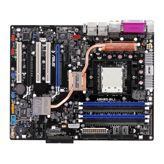
2.2.4 2.2.4 2.2.4 2.2.4 2.2.4 Motherboard layout Motherboard layout Motherboard layout Motherboard layout Motherboard layout PS/2KBMS T: Mouse B: Keyboard ATX12V SPDIF_O SPDIF_O2 AUDIO LAN1_USB12 LAN2_USB34 WIFI_G_USB10(USB910) CHA_FAN1 Marvell PCIE LAN SATA_RAID2 PCIEX4_1 PCIEX16_1 ® ACL850 PCI1 PCI2 FP_AUDIO PCIEX16_2... -
Page 31: Layout Contents
2.2.5 2.2.5 2.2.5 2.2.5 2.2.5 Layout contents Layout contents Layout contents Layout contents Layout contents S l o t s S l o t s S l o t s S l o t s S l o t s DDR DIMM slots PCI slots PCI Express x 4 slot... - Page 32 I n t e r n a l c o n n e c t o r s I n t e r n a l c o n n e c t o r s I n t e r n a l c o n n e c t o r s I n t e r n a l c o n n e c t o r s I n t e r n a l c o n n e c t o r s Floppy disk drive connector (34-1 pin FLOPPY)
-
Page 33: Central Processing Unit (Cpu)
2.3.1 2.3.1 Overview Overview The motherboard comes with a surface mount 939-pin Zero Insertion Force (ZIF) socket designed for the AMD Athlon™ 64FX/64 X2/64 and Sempron™ processor. The 128-bit-wide data paths of these processors can run applications faster than processors with only 32-bit or 64-bit wide data paths. - Page 34 Position the CPU above the socket such that the CPU corner with the gold triangle matches the socket corner with a small triangle. Carefully insert the CPU into the socket until it fits in place. The CPU fits only in one correct orientation. DO NOT force the CPU into the socket to prevent bending the pins and damaging the CPU! When the CPU is in place, push down the socket lever to secure...
-
Page 35: Installing The Heatsink And Fan
Place the heatsink on top of the installed CPU, making sure that the heatsink fits properly on the retention module base. • The retention module base is already installed on the motherboard upon purchase. • You do not have to remove the retention module base when installing the CPU or installing other motherboard components. - Page 36 Attach one end of the retention bracket to the retention module base. Align the other end of the retention bracket (near the retention bracket lock) to the retention module base until the retention bracket clicks in place. Make sure that the fan and heatsink assembly perfectly fits the retention mechanism module base, otherwise you...
- Page 37 When the fan and heatsink assembly is in place, connect the CPU fan cable to the connector on the motherboard labeled CPU_FAN. ® A8N32-SLI CPU fan connector Do not forget to connect the CPU fan connector! Hardware monitoring errors can occur if you fail to plug this connector.
-
Page 38: System Memory
2.4.1 2.4.1 Overview Overview Overview The motherboard comes with four 184-pin Double Data Rate (DDR) Dual Inline Memory Modules (DIMM) sockets. The following figure illustrates the location of the sockets: ® A8N32-SLI 184-pin DDR DIMM sockets C h a n n e l... - Page 39 Supports two pairs of modules inserted into the blue and black slots as two pairs of Dual-channel memory configuration. Visit the ASUS website for the latest QVL. A S U S A 8 N 3 2 - S L I D e l u x e...
- Page 40 C C C C C Supports two pairs of modules inserted into the blue and black slots as two pairs of Dual-channel memory configuration. Visit the ASUS website for the latest QVL. 2 - 1 4 2 - 1 4...
- Page 41 Supports two pairs of modules inserted into the blue and black slots as two pairs of Dual-channel memory configuration. Visit the ASUS website for the latest QVL. A S U S A 8 N 3 2 - S L I D e l u x e...
-
Page 42: Installing A Dimm
Make sure to unplug the power supply before adding or removing DIMMs or other system components. Failure to do so may cause severe damage to both the motherboard and the components. Unlock a DIMM socket by pressing the retaining clips outward. -
Page 43: Expansion Slots
Before installing the expansion card, read the documentation that came with it and make the necessary hardware settings for the card. Remove the system unit cover (if your motherboard is already installed in a chassis). Remove the bracket opposite the slot that you intend to use. Keep the screw for later use. -
Page 44: Interrupt Assignments
P r i o r i t y — * These IRQs are usually available for ISA or PCI devices. IRQ assignments for this motherboard IRQ assignments for this motherboard IRQ assignments for this motherboard IRQ assignments for this motherboard... -
Page 45: Pci Slots
Dual-GPU graphics card on the blue x16 slot, it runs at x8 speed for one of the two GPUs. • Due to NVIDIA nForce4 SLI x16 chipset limitations, this motherboard does not support two dual-GPU graphics cards (total 4 GPUs) running in SLI mode. -
Page 46: Clear Rtc Ram
Except when clearing the RTC RAM, never remove the cap on CLRTC jumper default position. Removing the cap will cause system boot failure! ® A8N32-SLI Clear RTC RAM • Make sure to re-enter your previous BIOS settings after you clear the CMOS. -
Page 47: Connectors
Connectors 2.7.1 2.7.1 2.7.1 Rear panel connectors Rear panel connectors Rear panel connectors 2.7.1 2.7.1 Rear panel connectors Rear panel connectors 1 . 1 . P S / 2 m o u s e p o r t ( g r e e n ) . This port is for a PS/2 mouse. P S / 2 m o u s e p o r t ( g r e e n ) . - Page 48 7 . 7 . L A N 1 ( R J - 4 5 ) p o r t . L A N 1 ( R J - 4 5 ) p o r t . L A N 1 ( R J - 4 5 ) p o r t . L A N 1 ( R J - 4 5 ) p o r t .
- Page 49 1 6 . 1 6 . 1 6 . E x t e r n a l S A T A p o r t . E x t e r n a l S A T A p o r t . This port connects to an external SATA box E x t e r n a l S A T A p o r t .
-
Page 50: Internal Connectors
FDD cable with a covered Pin 5. ® A8N32-SLI Floppy disk drive connector 2 . 2 . I D E c o n n e c t o r s ( 4 0 - 1 p i n P R I _ I D E , S E C _ I D E ) - Page 51 ® A8N32-SLI IDE connectors 3 . 3 . n V I D I A n V I D I A n V I D I A n V I D I A n V I D I A ® ® ® ® ®...
- Page 52 S i l i c o n 3 1 3 2 C o n t r o l l e r section “4.4.6 Onboard Devices Configuration” for details. ® A8N32-SLI SATA RAID connector • Before creating a RAID set using Serial ATA hard disks, make sure that you have connected the Serial ATA signal cable and installed Serial ATA hard disk drives;...
- Page 53 These connectors allow you to receive stereo audio input from sound sources such as a CD-ROM, TV-tuner, or MPEG card. ® A8N32-SLI Internal audio connectors Due to system resource allocation, the function of the AUX connector is disabled under 8-channel mode.
- Page 54 AC ‘97 audio standard. Connect one end of the front panel audio I/O module cable to this connector. ® A8N32-SLI Front panel audio connector 8 . 8 . IEEE 1394 port connectors (10-1 pin IE1394_1;IE1394_2) IEEE 1394 port connectors (10-1 pin IE1394_1;IE1394_2) IEEE 1394 port connectors (10-1 pin IE1394_1;IE1394_2)
- Page 55 ® A8N32-SLI COM port connector A S U S A 8 N 3 2 - S L I D e l u x e A S U S A 8 N 3 2 - S L I D e l u x e...
- Page 56 SB_FAN ® CHA_FAN2 A8N32-SLI Fan connectors Only the CPU_FAN and CHA_FAN1 connectors support the ASUS Q-Fan 2 feature. • Install an additional chassis fan when you are using two PCI Express graphics cards or a dual-core processor for better thermal environment.
- Page 57 ® A8N32-SLI Chassis intrusion connector A S U S A 8 N 3 2 - S L I D e l u x e A S U S A 8 N 3 2 - S L I D e l u x e...
-
Page 58: Atx Power Connectors
Find the proper orientation and push down firmly until the connectors completely fit. ® A8N32-SLI ATX power connectors • For a fully configured system, we recommend that you use a power supply unit (PSU) that complies with ATX 12 V Specification 2.0 (or later version) and provides a minimum power of 500 W. -
Page 59: System Panel Connector
S y s t e m p a n e l c o n n e c t o r ( 2 0 - p i n P A N E L ) This connector supports several chassis-mounted functions. ® A8N32-SLI System panel connector The sytem panel connector is color-coded for easy connection. Refer to the connector description below for details. -
Page 60: Installing The Optional Fan
Carefully push down the fan until it snugly fits the heatsink, then connect the fan cables. Plug the optional fan cables to the NB_FAN and/or PWR_FAN connector on the motherboard. 2 - 3 4 2 - 3 4 2 - 3 4... - Page 61 Make sure the optional fan is installed correctly to prevent damage to the fan and motherboard components. Do not tilt the fan. A S U S A 8 N 3 2 - S L I D e l u x e...
- Page 62 2 - 3 6 2 - 3 6 2 - 3 6 2 - 3 6 2 - 3 6 C h a p t e r 2 : H a r d w a r e i n f o r m a t i o n C h a p t e r 2 : H a r d w a r e i n f o r m a t i o n C h a p t e r 2 : H a r d w a r e i n f o r m a t i o n C h a p t e r 2 : H a r d w a r e i n f o r m a t i o n...
- Page 63 This chapter describes the power up sequence, the vocal POST messages, and ways of shutting down the system. Powering up...
-
Page 64: Chapter Summary
Chapter summary Starting up for the first time ... 3-1 Powering off the computer ... 3-2 A S U S A 8 N 3 2 - S L I D e l u x e A S U S A 8 N 3 2 - S L I D e l u x e A S U S A 8 N 3 2 - S L I D e l u x e A S U S A 8 N 3 2 - S L I D e l u x e A S U S A 8 N 3 2 - S L I D e l u x e... -
Page 65: Starting Up For The First Time
Starting up for the first time After making all the connections, replace the system case cover. Be sure that all switches are off. Connect the power cord to the power connector at the back of the system chassis. Connect the power cord to a power outlet that is equipped with a surge protector. -
Page 66: Powering Off The Computer
Powering off the computer 3.2.1 3.2.1 3.2.1 Using the OS shut down function Using the OS shut down function Using the OS shut down function 3.2.1 3.2.1 Using the OS shut down function Using the OS shut down function If you are using Windows ®... -
Page 67: Chapter 4: Bios Setup
This chapter tells how to change the system settings through the BIOS Setup menus. Detailed descriptions of the BIOS parameters are also provided. BIOS setup... - Page 68 Chapter summary Managing and updating your BIOS ... 4-1 BIOS setup program ... 4-11 Main menu ... 4-14 Advanced menu ... 4-19 Power menu ... 4-33 Boot menu ... 4-37 Exit menu ... 4-42 A S U S A 8 N 3 2 - S L I D e l u x e A S U S A 8 N 3 2 - S L I D e l u x e A S U S A 8 N 3 2 - S L I D e l u x e A S U S A 8 N 3 2 - S L I D e l u x e...
-
Page 69: Managing And Updating Your Bios
Refer to the corresponding sections for details on these utilities. Save a copy of the original motherboard BIOS file to a bootable floppy disk in case you need to restore the BIOS in the future. Copy the original motherboard BIOS using the ASUS Update or AFUDOS utilities. 4.1.1 4.1.1 4.1.1... -
Page 70: Windows ® 2000 Environment
O p e n field, type D:\bootdisk\makeboot a: O p e n assuming that D is your optical drive letter. e. Press <Enter>, then follow screen instructions to continue. Copy the original or the latest motherboard BIOS file to the bootable floppy disk. 4.1.2 4.1.2 4.1.2... - Page 71 Updating the BIOS file To update the BIOS file using the AFUDOS utility: Visit the ASUS website (www.asus.com) and download the latest BIOS file for the motherboard. Save the BIOS file to a bootable floppy disk. Write the BIOS filename on a piece of paper. You need to type the exact BIOS filename at the DOS prompt.
- Page 72 The utility verifies the file and starts updating the BIOS. A:\>afudos /iA8N32SLI.ROM AMI Firmware Update Utility - Version 1.19(ASUS V2.07(03.11.24BB)) Copyright (C) 2002 American Megatrends, Inc. All rights reserved. WARNING!! Do not turn off power during flash BIOS Reading file ... done Reading flash ...
-
Page 73: Asus Crashfree Bios 2 Utility
ASUS CrashFree BIOS 2 utility ASUS CrashFree BIOS 2 utility The ASUS CrashFree BIOS 2 is an auto recovery tool that allows you to restore the BIOS file when it fails or gets corrupted during the updating process. You can update a corrupted BIOS file using the motherboard support CD or the floppy disk that contains the updated BIOS file. - Page 74 Restart the system after the utility completes the updating process. The recovered BIOS may not be the latest BIOS version for this motherboard. Visit the ASUS website (www.asus.com) to download the latest BIOS file. 4 - 6...
-
Page 75: Asus Ez Flash Utility
Visit the ASUS website (www.asus.com) to download the latest BIOS file for the motherboard and rename the same to A 8 N 3 2 S L I . R O M Save the BIOS file to a floppy disk, then restart the system. -
Page 76: Asus Update Utility
ASUS Update utility ASUS Update utility ASUS Update utility ASUS Update utility The ASUS Update is a utility that allows you to manage, save, and update the motherboard BIOS in Windows allows you to: • Save the current BIOS file •... - Page 77 Updating the BIOS through the Internet Updating the BIOS through the Internet To update the BIOS through the Internet: Launch the ASUS Update utility from the Windows S t a r t S t a r t P r o g r a m s...
- Page 78 A S U S U p d a t e A S U S U p d a t e A S U S U p d a t e. The ASUS Update main window appears. A S U S U p d a t e...
-
Page 79: Bios Setup Program
• Visit the ASUS website (www.asus.com) to download the latest BIOS file for this motherboard. A S U S A 8 N 3 2 - S L I D e l u x e... -
Page 80: Menu Bar
4.2.1 4.2.1 4.2.1 4.2.1 4.2.1 BIOS menu screen BIOS menu screen BIOS menu screen BIOS menu screen BIOS menu screen M e n u i t e m s M e n u i t e m s M e n u i t e m s M e n u i t e m s M e n u i t e m s M e n u b a r... -
Page 81: Menu Items
Language [English] Use [+] or [-] to Primary IDE Master :[ST320413A] configure system time. Primary IDE Slave :[ASUS CD-S340] Secondary IDE Master :[Not Detected] Secondary IDE Slave :[Not Detected] Third IDE Master :[Not Detected] Fourth IDE Master... -
Page 82: Main Menu
Main menu When you enter the BIOS Setup program, the M a i n giving you an overview of the basic system information. Refer to section “4.2.1 BIOS menu screen” for information on the menu screen items and how to navigate through them. Main Advanced Server... -
Page 83: Primary, Secondary, Third, Fourth, Fifth
4.3.5 4.3.5 4.3.5 4.3.5 4.3.5 Primary, Secondary, Third, Fourth, Fifth, Primary, Secondary, Third, Fourth, Fifth, Primary, Secondary, Third, Fourth, Fifth, Primary, Secondary, Third, Fourth, Fifth, Primary, Secondary, Third, Fourth, Fifth, and Sixth IDE Master/Slave and Sixth IDE Master/Slave and Sixth IDE Master/Slave and Sixth IDE Master/Slave and Sixth IDE Master/Slave The BIOS automatically detects the connected IDE devices. -
Page 84: Pio Mode [Auto]
PIO Mode [Auto] PIO Mode [Auto] PIO Mode [Auto] PIO Mode [Auto] PIO Mode [Auto] Selects the PIO mode. Configuration options: [Auto] [0] [1] [2] [3] [4] DMA Mode [Auto] DMA Mode [Auto] DMA Mode [Auto] DMA Mode [Auto] DMA Mode [Auto] Sets the DMA mode. -
Page 85: Ide Configuration
4.3.6 4.3.6 4.3.6 4.3.6 4.3.6 IDE Configuration IDE Configuration IDE Configuration IDE Configuration IDE Configuration The items in this menu allow you to set or change the configurations for the IDE and Serial ATA devices installed in the system. Select an item, then press <Enter>... -
Page 86: System Information
4.3.7 4.3.7 4.3.7 4.3.7 4.3.7 System Information System Information System Information System Information System Information This menu gives you an overview of the general system specifications. The BIOS automatically detects the items in this menu. Main System Information AMIBIOS Version : 0128 Build Date : 09/05/05 Processor... -
Page 87: Advanced Menu
Advanced menu The Advanced menu items allow you to change the settings for the CPU and other system devices. Take caution when changing the settings of the Advanced menu items. Incorrect field values can cause the system to malfunction. BIOS SETUP UTILITY Main Advanced Power... -
Page 88: Amd Cool N' Quiet Configuration
4.4.2 4.4.2 4.4.2 4.4.2 4.4.2 AMD Cool N’ Quiet Configuration AMD Cool N’ Quiet Configuration AMD Cool N’ Quiet Configuration AMD Cool N’ Quiet Configuration AMD Cool N’ Quiet Configuration The items in this menu allows you to enable the AMD Cool N’ Quiet feature. Advanced AMD Cool N’... - Page 89 A I N . O . S . A I N . O . S . A I N . O . S . - the ASUS AI Non-delay Overclocking System feature intelligently determines the system load and automatically boosts the performance for the most demanding tasks...
- Page 90 PEG Link Mode [Auto] PEG Link Mode [Auto] PEG Link Mode [Auto] PEG Link Mode [Auto] PEG Link Mode [Auto] This option may effectively boost PEG performance. If system become unstable, please set to [Normal] or [Auto] for safe mode. Over-Voltage CPU VCORE [Disabled] Over-Voltage CPU VCORE [Disabled] Over-Voltage CPU VCORE [Disabled]...
- Page 91 Processor Frequency Multiplier [8X] Processor Frequency Multiplier [8X] Processor Frequency Multiplier [8X] Processor Frequency Multiplier [8X] Processor Frequency Multiplier [8X] Allows you to set the CPU frequency multiplier. Configuration options: [6X] [6.5X] [7X] [7.5X] [8X] [8.5X] [9X] [9.5X][10X] Processor Voltage [1.425V] Processor Voltage [1.425V] Processor Voltage [1.425V] Processor Voltage [1.425V]...
-
Page 92: Cpu Configuration
4.4.4 4.4.4 4.4.4 4.4.4 4.4.4 CPU Configuration CPU Configuration CPU Configuration CPU Configuration CPU Configuration The items in this menu show the CPU-related information that the BIOS automatically detects. Advanced CPU Configuration Module Version: 14.04 Physical Count: 1 Logical Count : 1 AMD Sempron(tm) Processor 3000+ Revision : E6 Cache L1 : 64KB... - Page 93 M e m o r y C o n f i g u r a t i o n M e m o r y C o n f i g u r a t i o n M e m o r y C o n f i g u r a t i o n M e m o r y C o n f i g u r a t i o n M e m o r y C o n f i g u r a t i o n BIOS SETUP UTILITY...
- Page 94 TWCL [1] C o n f i g u r a t i o n o p t i o n s : [ 1 ] [ 2 ] C o n f i g u r a t i o n o p t i o n s : [ 1 ] [ 2 ] C o n f i g u r a t i o n o p t i o n s : [ 1 ] [ 2 ] C o n f i g u r a t i o n o p t i o n s : [ 1 ] [ 2 ] C o n f i g u r a t i o n o p t i o n s : [ 1 ] [ 2 ]...
-
Page 95: Dram Ecc Enable [Enabled]
E C C C o n f i g u r a t i o n E C C C o n f i g u r a t i o n E C C C o n f i g u r a t i o n E C C C o n f i g u r a t i o n E C C C o n f i g u r a t i o n BIOS SETUP UTILITY... -
Page 96: Chipset
Data Cache BG Scrub [Disabled] Data Cache BG Scrub [Disabled] Data Cache BG Scrub [Disabled] Data Cache BG Scrub [Disabled] Data Cache BG Scrub [Disabled] Sets automatic correction of L1 data cache RAM when idle. Configuration options: [Disabled] [40ns] [80ns] [160ns] [320ns] [640ns] [1.28us] [2.56us] [5.12us] [10.2us] [20.5us] [41.0us] [81.9us] [163.8us] [327.7us] [655.4us] [1.31ms] [2.62ms] [5.24ms] [10.49ms] [20.97ms] [42.00ms] [84.00ms]... -
Page 97: Onboard Devices Configuration
4.4.6 4.4.6 4.4.6 4.4.6 4.4.6 Onboard Devices Configuration Onboard Devices Configuration Onboard Devices Configuration Onboard Devices Configuration Onboard Devices Configuration BIOS SETUP UTILITY Advanced Configure ITE8712 Super IO Chipset Serial Port1 Address [3F8/IRQ4] Parallel Port Address [378] Parallel Port Mode [EPP+ECP] EPP Version [1.9]... - Page 98 Onboard MIDI Port [330] Onboard MIDI Port [330] Onboard MIDI Port [330] Onboard MIDI Port [330] Onboard MIDI Port [330] Allows you to disable or to set the MIDI port address. Configuration options: [Disabled] [300] [330] MIDI IRQ Select [IRQ5] Configuration options: [IRQ5] [IRQ7] [IRQ10] [IRQ11] 1394 [Enabled] 1394 [Enabled]...
-
Page 99: Pcipnp
4.4.7 4.4.7 4.4.7 4.4.7 4.4.7 PCIPnP PCIPnP PCIPnP PCIPnP PCIPnP The PCIPnP menu items allow you to change the advanced settings for PCI/ PnP devices. The menu includes setting IRQ and DMA channel resources for either PCI/PnP or legacy ISA devices, and setting the memory size block for legacy ISA devices. -
Page 100: Usb Configuration
4.4.8 4.4.8 4.4.8 4.4.8 4.4.8 USB Configuration USB Configuration USB Configuration USB Configuration USB Configuration The items in this menu allows you to change the USB-related features. Select an item then press <Enter> to display the configuration options. Advanced USB Configuration Module Version - 2.24.2-11.4 USB Devices Enabled: None USB 1.1 Controller... -
Page 101: Power Menu
Power menu The Power menu items allow you to change the settings for the ACPI and Advanced Power Management (APM) features. Select an item then press <Enter> to display the configuration options. BIOS SETUP UTILITY Power Suspend Mode [Auto] Repost Video on S3 Resume [No] ACPI APIC Support [Enabled]... -
Page 102: Apm Configuration
4.5.4 4.5.4 4.5.4 4.5.4 4.5.4 APM Configuration APM Configuration APM Configuration APM Configuration APM Configuration Power Restore on AC Power Loss Power On By PME# Power On By LAN(MAC) Power On By Ring Power On By PS/2 Keyboard Power On By PS/2 Mouse Power On By RTC Alarm V00.00 (C)Copyright 1985-2004, American Megatrends, Inc. -
Page 103: System Time
Power On By PS/2 Keyboard [Disabled] Power On By PS/2 Keyboard [Disabled] Power On By PS/2 Keyboard [Disabled] Power On By PS/2 Keyboard [Disabled] Power On By PS/2 Keyboard [Disabled] Allows you to use specific keys on the keyboard to turn on the system. This feature requires an ATX power supply that provides at least 1A on the +5VSB lead. -
Page 104: Hardware Monitor
Q-FAN Control [Disabled] Q-FAN Control [Disabled] Q-FAN Control [Disabled] Q-FAN Control [Disabled] Allows you to enable or disable the ASUS Q-Fan feature that smartly adjusts the fan speeds for more efficient system operation. Configuration options: [Disabled] [Enabled] 4 - 3 6... -
Page 105: Boot Menu
Boot menu The Boot menu items allow you to change the system boot options. Select an item then press <Enter> to display the sub-menu. BIOS SETUP UTILITY Main Advanced Power Boot Boot Device Priority Boot Settings Configuration Security V00.00 (C)Copyright 1985-2004, American Megatrends, Inc. 4.6.1 4.6.1 4.6.1... -
Page 106: Boot Settings Configuration
Allows you to enable or disable the full screen logo display feature. Configuration options: [Disabled] [Enabled] Set this item to [Enabled] to use the ASUS MyLogo2™ feature. Add On ROM Display Mode [Force BIOS] Add On ROM Display Mode [Force BIOS]... -
Page 107: Hit 'Del' Message Display [Enabled]
Hit ‘DEL’ Message Display [Enabled] Hit ‘DEL’ Message Display [Enabled] Hit ‘DEL’ Message Display [Enabled] Hit ‘DEL’ Message Display [Enabled] Hit ‘DEL’ Message Display [Enabled] When set to Enabled, the system displays the message “Press DEL to run Setup” during POST. Configuration options: [Disabled] [Enabled] Interrupt 19 Capture [Disabled] Interrupt 19 Capture [Disabled] Interrupt 19 Capture [Disabled]... -
Page 108: User Access Level [Full Access]
If you forget your BIOS password, you can clear it by erasing the CMOS Real Time Clock (RTC) RAM. See section “2.6 Jumpers” for information on how to erase the RTC RAM. After you have set a supervisor password, the other items appear to allow you to change other security settings. -
Page 109: Password Check [Setup]
To set a User Password: Select the Change User Password item and press <Enter>. On the password box that appears, type a password composed of at least six letters and/or numbers, then press <Enter>. Confirm the password when prompted. The message “Password Installed” appears after you set your password successfully. -
Page 110: Exit Menu
Exit menu The Exit menu items allow you to load the optimal or failsafe default values for the BIOS items, and save or discard your changes to the BIOS items. Main Advanced Power Save Changes and Exit Discard Changes and Exit Discard Changes Load Setup Defaults V00.00 (C)Copyright 1985-2004, American Megatrends, Inc. -
Page 111: Load Setup Defaults
Load Setup Defaults Load Setup Defaults Load Setup Defaults Load Setup Defaults Load Setup Defaults Allows you to load the default values for each of the parameters on the Setup menus. When you select this option or if you press <F5>, a confirmation window appears. -
Page 112: Software Support
This chapter describes the contents of the support CD that comes with the motherboard package. Software support... -
Page 113: Chapter Summary
Chapter summary Installing an operating system ... 5-1 Support CD information ... 5-1 Software information ... 5-9 RAID configurations ... 5-25 Creating a RAID driver disk ... 5-41 A S U S A 8 N 3 2 - S L I D e l u x e A S U S A 8 N 3 2 - S L I D e l u x e A S U S A 8 N 3 2 - S L I D e l u x e A S U S A 8 N 3 2 - S L I D e l u x e... -
Page 114: Installing An Operating System
The support CD that came with the motherboard package contains the drivers, software applications, and utilities that you can install to avail all motherboard features. The contents of the support CD are subject to change at any time without notice. Visit the ASUS website(www.asus.com) for updates. 5.2.1 5.2.1 5.2.1 5.2.1... -
Page 115: Drivers Menu
5.2.2 5.2.2 5.2.2 5.2.2 5.2.2 Drivers menu Drivers menu Drivers menu Drivers menu Drivers menu The drivers menu shows the available device drivers if the system detects installed devices. Install the necessary drivers to activate the devices. Nvidia Chipset Driver Program Nvidia Chipset Driver Program Nvidia Chipset Driver Program Nvidia Chipset Driver Program... -
Page 116: Utilities Menu
ASUS Update ASUS Update ASUS Update ASUS Update ASUS Update The ASUS Update utility allows you to update the motherboard BIOS in Windows ® environment. This utility requires an Internet connection either through a network or an Internet Service Provider (ISP). -
Page 117: Make Disk Menu
Visit the Microsoft website (www.microsoft.com) for updates. ASUS Ai Booster ASUS Ai Booster ASUS Ai Booster ASUS Ai Booster ASUS Ai Booster This item installs the ASUS Ai Booster utility. Anti-virus Utility Anti-virus Utility Anti-virus Utility Anti-virus Utility Anti-virus Utility The anti-virus application scans, identifies, and removes computer viruses. -
Page 118: Manuals Menu
Silicon Image 64bit RAID Driver Silicon Image 64bit RAID Driver Silicon Image 64bit RAID Driver Silicon Image 64bit RAID Driver Silicon Image 64bit RAID Driver Silicon Image 64bit SATA Driver Silicon Image 64bit SATA Driver Silicon Image 64bit SATA Driver Silicon Image 64bit SATA Driver Silicon Image 64bit SATA Driver Allows you to create an Silicon Image 64bit RAID/SATA driver disk. -
Page 119: Asus Contact Information
ASUS Contact information Click the C o n t a c t C o n t a c t tab to display the ASUS contact information. You can C o n t a c t C o n t a c t C o n t a c t also find this information on the inside front cover of this user guide. -
Page 120: Browse This Cd
Technical support Form Technical support Form Displays the ASUS Technical Support Request Form that you have to fill out when requesting technical support. A S U S A 8 N 3 2 - S L I D e l u x e... - Page 121 Filelist Filelist Filelist Filelist Filelist Displays the contents of the support CD and a brief description of each in text format. 5 - 8 5 - 8 5 - 8 5 - 8 5 - 8 C h a p t e r 5 : S o f t w a r e s u p p o r t C h a p t e r 5 : S o f t w a r e s u p p o r t C h a p t e r 5 : S o f t w a r e s u p p o r t C h a p t e r 5 : S o f t w a r e s u p p o r t...
-
Page 122: Software Information
ASUS MyLogo2™ ASUS MyLogo2™ ASUS MyLogo2™ The ASUS MyLogo2™ utility lets you customize the boot logo. The boot logo is the image that appears on screen during the Power-On Self-Tests (POST). The ASUS MyLogo2™ is automatically installed when you install the... - Page 123 R a t i o box. R a t i o When the screen returns to the ASUS Update utility, flash the original BIOS to load the new boot logo. 10. After flashing the BIOS, restart the computer to display the new boot logo during POST.
-
Page 124: Ai Net
5.3.2 5.3.2 5.3.2 5.3.2 5.3.2 AI NET AI NET AI NET AI NET AI NET The Marvell ® Virtual Cable Tester™ (VCT) is a cable diagnostic utility that reports LAN cable faults and shorts using the Time Domain Reflectometry (TDR) technology. The VCT detects and reports open and shorted cables, impedance mismatches, pair swaps, pair polarity problems, and pair skew problems of up to 100 meters at one meter accuracy. -
Page 125: Audio Configurations
D r i v e r a n d A p p l i c a t i o n D r i v e r a n d A p p l i c a t i o n motherboard package. If the Realtek audio software is correctly installed, you will find the SoundEffect icon on the taskbar. - Page 126 To set the sound effect options: From the Realtek Audio Control Panel, click the S o u n d E f f e c t button. Click the shortcut buttons to change the acoustic environment, adjust the equalizer, or set the karaoke to your desired settings. The audio settings take effect immediately after you click on the buttons.
-
Page 127: Speaker Configuration
Speaker Configuration Speaker Configuration Speaker Configuration Speaker Configuration Speaker Configuration This option allows you to set your speaker configuration. To set the speaker configuration: From the Realtek Audio Control Panel, click the S p e a k e r C o n f i g u r a t i o n button. C o n f i g u r a t i o n C o n f i g u r a t i o n C o n f i g u r a t i o n... -
Page 128: Ai Audio Feature
AI Audio feature AI Audio feature AI Audio feature AI Audio feature AI Audio feature The AI Audio feature works through the connector sensing option that allows you to check if your audio devices are connected properly. To start the connector sensing: From the Realtek Audio Control Panel, click the C o n n e c t o r S e n s i n g button. -
Page 129: Audio Demo
If there are detected problems, make sure that your audio cables are connected to the proper audio jack and repeat connector sensing. Click the button to exit EZ-connection dialog box. Click the Exit ( ) button on the upper-right hand corner of the window to exit. -
Page 130: General Settings
General settings General settings General settings General settings General settings This option shows the audio settings and allows you to change the language setting or toggle the SoundEffect icon display on the Windows taskbar. To display the general settings: From the Realtek Audio Control Panel, click the G e n e r a l Click the option button to enable or disable the icon display on the Windows taskbar. -
Page 131: Using The Nvidia Firewall
Launching the NVFirewall™ summary Launching the NVFirewall™ summary After you install the NVFirewall™ application from the motherboard support CD, it is automatically activated with a M e d i u m default setting. The setup summary of NVFirewall™ is displayed in the summary menu. - Page 132 Setting security profiles Setting security profiles Setting security profiles Setting security profiles Setting security profiles The NVFirewall™ application allows several security profiles to match your system security needs. The following describes the NVFirewall™ security profiles: • L o w - allows safe incoming connections and deny those that are L o w L o w L o w...
- Page 133 Turning the NVFirewall™ off Turning the NVFirewall™ off Turning the NVFirewall™ off Turning the NVFirewall™ off Turning the NVFirewall™ off Take caution when using this option, your computer becomes vulnerable to viruses, hackers or intruders after you turn off the firewall. To turn off the NVFirewall™: From the NVIDIA Firewall™...
-
Page 134: Using The Wireless Lan Module
The wireless LAN module is an optional item. • For detailed information on using the Wireless LAN module, view/ download the RTL8187 Wireless LAN User’s Manual on the motherboard support CD. The wireless IEEE 802.11 b/g LAN module is installed on the rear panel. -
Page 135: Driver Installation
Driver installation Driver installation Driver installation Driver installation Driver installation If you are using a Windows auto-detects the wireless LAN module during start-up and displays an A d d N e w H a r d w a r e W i z a r d A d d N e w H a r d w a r e W i z a r d window. -
Page 136: Network Setup
Network setup Network setup Network setup Network setup Network setup You can use the wireless LAN module in various wireless network configurations. After installing the wireless LAN adapter drivers to your computer, select the most appropriate configuration for your home or office wireless network. -
Page 137: Configuration Options
Configuration options Configuration options Configuration options Configuration options Configuration options Below are some of the wireless network configurations that you can use for your wireless LAN module. The following descriptions are for reference only and may not exactly match your actual network configuration. Ad-hoc mode A d - h o c A d - h o c... -
Page 138: Raid Configurations
The motherboard comes with the Silicon Image Sil3132 and the NVIDIA nForce™ 4 SLI Southbridge RAID controllers that allow you to configure Serial ATA hard disk drives as RAID sets. The motherboard supports the following RAID configurations. R A I D 0... -
Page 139: Installing Hard Disks
Connect the SATA signal cables. Connect a SATA power cable to the power connector on each drive. Refer to the RAID controllers user manual in the motherboard support CD for detailed information on RAID configurations. See section “5.2.4 Manuals menu.”... -
Page 140: Nvidia Raid Configurations
RAID configurations RAID configurations RAID configurations RAID configurations The motherboard includes a high performance IDE RAID controller integrated in the NVIDIA ® nForce™ 4 SLI southbridge chipset. It supports RAID 0, RAID 1, RAID 0+1, RAID 5 and JBOD for four independent Serial ATA channels. -
Page 141: Raid Utility
Entering the NVIDIA Entering the NVIDIA Entering the NVIDIA Entering the NVIDIA Entering the NVIDIA ® ® ® ® ® To enter the NVIDIA ® RAID utility: Boot up your computer. During POST, press <F10> to display the main menu of the utility. The RAID BIOS setup screens shown in this section are for reference only, and may not exactly match the items on your screen. - Page 142 Press <TAB> select the Striping Block then press <Enter>. The following submenu appears: If you selected Striping or Stripe Mirroring, use the up or down arrow keys to select the stripe size for your RAID 0 array then press <Enter>.The available values range from 8 KB to 128 KB. The default selection is 128 KB.
-
Page 143: Rebuilding A Raid Array
NVIDIA RAID Utility Boot ↑↓ ↑↓ ↑↓]Select ↑↓ [Ctrl-X]Exit [↑↓ A new set of navigation keys is displayed on the bottom of the screen. Press <Ctrl+X> to save settings and exit. Rebuilding a RAID array Rebuilding a RAID array Rebuilding a RAID array Rebuilding a RAID array Rebuilding a RAID array To rebuild a RAID array:... - Page 144 A new set of navigation keys is displayed on the bottom of the screen. Press <R> to rebuild a RAID array. The following screen appears. Array 1 : NVIDIA MIRROR - Select Disk Inside Array - RAID Mode: Mirroring Striping Width: 1 Adapt Channel Index...
-
Page 145: Deleting A Raid Array
Deleting a RAID array Deleting a RAID array Deleting a RAID array Deleting a RAID array Deleting a RAID array To delete a RAID array: From the Array List menu, use the up or down arrow keys to select a RAID array then press <Enter>. - Page 146 Clearing a disk data Clearing a disk data Clearing a disk data Clearing a disk data Clearing a disk data To clear disk data: From the Array List menu, use the up or down arrow keys to select a RAID array then press <Enter>. The RAID Array details appear. Array 1 : NVIDIA MIRROR - Array Detail - RAID Mode: Mirroring...
-
Page 147: Silicon Image Raid Configurations
> S a m > S a m For details on the Silicon Image SATARaid™ RAID configuration, refer to the “Sil3132 SATA RAID User’s Manual” in your motherboard support 5 - 3 4 5 - 3 4 5 - 3 4... -
Page 148: Entering The Silicon Image Bios Raid Configuration Utility
Entering the Silicon Image BIOS RAID Configuration Utility Entering the Silicon Image BIOS RAID Configuration Utility Entering the Silicon Image BIOS RAID Configuration Utility Entering the Silicon Image BIOS RAID Configuration Utility Entering the Silicon Image BIOS RAID Configuration Utility To enter the Silicon Image BIOS RAID configuration utility: Boot up your computer. -
Page 149: Creating A Raid 0 Set (Striped)
Creating a RAID 0 set (Striped) Creating a RAID 0 set (Striped) Creating a RAID 0 set (Striped) Creating a RAID 0 set (Striped) Creating a RAID 0 set (Striped) To create a RAID set: From the Silicon Image configuration utility main menu, select C r e a t e R A I D s e t C r e a t e R A I D s e t... -
Page 150: Creating A Raid 1 Set (Mirrored)
T I P : T I P : T I P : For server systems, we recommend using a lower array block size. T I P : T I P : For multimedia computer systems used mainly for audio and video editing, we recommend a higher array block size for optimum performance. - Page 151 Select your desired method of configuration. A u t o c o n f i g u r a t i o n A u t o c o n f i g u r a t i o n A u t o c o n f i g u r a t i o n A u t o c o n f i g u r a t i o n A u t o c o n f i g u r a t i o n...
- Page 152 e. If you selected MAIN MENU C r e a t e w i t h d a t a C r e a t e w i t h d a t a C r e a t e w i t h d a t a C r e a t e w i t h d a t a C r e a t e w i t h d a t a Auto configuration...
-
Page 153: Creating A Concatenation Set
Creating a CONCATENATION set Creating a CONCATENATION set Creating a CONCATENATION set Creating a CONCATENATION set Creating a CONCATENATION set To create a CONCATENATION set: From the Silicon Image configuration utility main menu, select C r e a t e R A I D s e t C r e a t e R A I D s e t C r e a t e R A I D s e t C r e a t e R A I D s e t... -
Page 154: Creating A Raid Driver Disk
2000/XP operating system on a hard disk drive that is included in a RAID set. To create a RAID driver disk: Place the motherboard support CD into the CD-ROM drive. Select M a k e D i s k M a k e D i s k M a k e D i s k M a k e D i s k tab. - Page 155 This chapter tells how to install SLI-ready PCI Express graphics cards. ® NVIDIA SLI™ technology support...
- Page 156 Chapter summary Overview ... 6-1 Dual graphics cards setup ... 6-2 A S U S A 8 N 3 2 - S L I D e l u x e A S U S A 8 N 3 2 - S L I D e l u x e A S U S A 8 N 3 2 - S L I D e l u x e A S U S A 8 N 3 2 - S L I D e l u x e A S U S A 8 N 3 2 - S L I D e l u x e...
-
Page 157: Overview
NVIDIA ® certified. • Visit the ASUS website (www.asus.com) for a list of qualified SLI-ready graphics cards for this motherboard. • Make sure that your graphics card driver supports the NVIDIA SLI technology. Download the latest driver from the NVIDIA website (www.nvidia.com). -
Page 158: Dual Graphics Card Setup
Dual graphics card setup 6.2.1 6.2.1 6.2.1 Installing SLI-ready graphics cards Installing SLI-ready graphics cards Installing SLI-ready graphics cards 6.2.1 6.2.1 Installing SLI-ready graphics cards Installing SLI-ready graphics cards Install only identical SLI-ready graphics cards that are NVIDIA Different types of graphics cards will not work together properly. To install the graphics cards: Prepare two graphics cards. - Page 159 Insert one graphics card into either the blue or black slot. Make sure that the card is properly seated on the slot. Insert the second graphics card into the other slot. Make sure that the card is properly seated on the slot. If required, connect an auxiliary power source to the PCI Express graphics cards.
- Page 160 Connect a 4-pin ATX power cable to the EZ Plug™ labeled E Z _ P L U G on your motherboard. Make sure to connect a 4-pin ATX power cable to the EZ Plug; otherwise, the system will be unstable. ® A8N32-SLI ATX power connectors 6 - 4 6 - 4 6 - 4 6 - 4...
- Page 161 Align and insert the retention bracket into the slot then secure it with a screw. Make sure that the retention bracket firmly supports the two graphics cards. Connect a V G A c a b l e V G A c a b l e V G A c a b l e V G A c a b l e or a D V I - I c a b l e V G A c a b l e...
-
Page 162: Installing The Device Drivers
6.2.2 6.2.2 6.2.2 6.2.2 6.2.2 Installing the device drivers Installing the device drivers Installing the device drivers Installing the device drivers Installing the device drivers Refer to the documentation that came with your graphics card package to install the device drivers. Make sure that your PCI Express graphics card driver supports the NVIDIA SLI technology. - Page 163 From the nView Desktop Manager D e s k t o p D e s k t o p window, select the D e s k t o p D e s k t o p D e s k t o p M a n a g e m e n t M a n a g e m e n t M a n a g e m e n t tab.
- Page 164 Click the slider to display the following screen, then select the S L I m u l t i - G P U item. m u l t i - G P U m u l t i - G P U m u l t i - G P U m u l t i - G P U Click the E n a b l e S L I m u l t i - G P U...
Need help?
Do you have a question about the A8N32-SLI and is the answer not in the manual?
Questions and answers