
Related Manuals for Dolby Laboratories CP65


Summary of Contents for Dolby Laboratories CP65
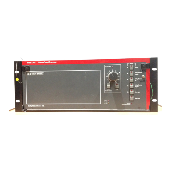
- Page 1 Model CP65 Cinema Processor Installation and Alignment Instructions Issue 4 Part No. 91234...
- Page 2 Laboratories be liable for incidental, special, direct, indirect or consequential damages (including but not limited to damage to software or recorded audio or visual material), or loss of use, revenue or profit even if Dolby Laboratories or its agents have been advised, orally or in writing, of the possibility of such damages.
-
Page 3: Table Of Contents
Model CP65 Cinema Processor Installation and Alignment Instructions INTRODUCTION ... v CP65 ... v CP65-A ... v CP65-300... v About this manual... v SECTION 1 EQUIPMENT REQUIRED ... 1-1 SECTION 2 INITIAL SET-UP AND INSTALLATION ... 2-1 Wiring Diagrams ... 2-3 Jumpers on Boards Cat. - Page 4 Model CP65 Cinema Processor Installation and Alignment Instructions SECTION 6 REFERENCE BLOCK DIAGRAMS ... 6-1 APPENDIX A Checking Phasing of Speakers APPENDIX B Effect of Changes in Slit Height on Slit Losses APPENDIX C CP65M (Mono) Instructions APPENDIX D Backplane Connections Listing...
-
Page 5: Introduction
This manual contains essential information on the installation and alignment of the CP65 Cinema Sound Processor. The CP65 supersedes the CP55 and is available in three versions: CP65 The standard configuration, equipped for the reproduction of the following sound formats 01 Mono–for all optical prints of any vintage with conventional mono optical... -
Page 6: Section 4 A-Chain Alignment
Dolby noise reduction adjustments—and the B- chain alignment which covers the portions of the system from the room equalization circuits to the CP65 fader through to the loudspeakers. The alignment instructions in this Manual are presented in three columns. The first column, Action, contains a drawing of the item to be adjusted and a caption containing a brief description of the action to be taken. -
Page 7: Section 1 Equipment Required
Cat. No. 85C pink noise generator. e. Cat. No. 67 extender for the equalizer modules. f. Test Films (available from Dolby Laboratories or equipment dealers). We recommend that you make loops of these test films, sufficiently long to go through the entire projector film path so that azimuth and lateral film position adjustments can be made accurately. - Page 8 Stereo Optical Surround Level — Cat. No. 151 g. The following films can also be purchased from Dolby Laboratories or a cinema equipment dealer. The films are optional items that are used in final system sound verification: (1) “Jiffy” Test Film — Cat. No. 251...
-
Page 9: Section 2 Initial Set-Up And Installation
BYPASS; you can then safely remove or replace the desired card without disconnecting power from the CP65. Do NOT connect the CP65 to mains power until all connections have been made and all jumpers have been installed (see STEP 9 later in this section). -
Page 10: Wiring Diagrams
STEP 8 If you plan to make use of the automation interface in the CP65, there are two methods you can follow. If both remote switches and their accompanying indicators for format, mute, and local / remote fader control are required you should use the 25 way D type connector J18. -
Page 11: Cat. No. 441
STEP 9 Next, check the jumpers in the following locations: Cat. No. 441 Surround Equalization, Subwoofer and SR•D Interface Card (if fitted). The Cat. No. 441 has four jumpers that are used to configure the card to suit the installation in which it is used. -
Page 12: Cat. No. 242
Cat. No. 242, B-Chain Card frequency filter OFF J1 Mono LF cut In/Out: selects optional low frequency cut when Mono (format 01) is selected. In some cases the extended low frequency reponse may appear to be out of balance with the restricted high frequency response needed for the correct reproduction of mono optical sound-tracks. -
Page 13: Cat. No. 443
Cat. No. 443, Control Logic Card Allows diodes in the spare column to disable the Edgecode reader Turns off surround channel in non-sync Position the jumper to NS 2:4 the desired SR•D wake-up format Spare jumper Non-sync mode Cat. No. 443 There are four programmable-link jumpers J1-J4 and two hard-wired links J5 and J6. -
Page 14: Cp65 Backplane
Standard CP65 or CP65A In a standard CP65 (fitted with one Cat. No. 222 and two Cat. No. 350 SR modules) or a CP65-A (fitted with one Cat. No. 222 only) links J16 and J17 should be fitted so that... - Page 15 CP65-300 In a CP65-300 (when Cat. No. 300 modules are fitted in place of the normal Cat. No. 350 modules) J16 and J18 should be rotated so that the words “Format 42” appears the right way up. With J24 in the “NR” position input signals will be A-type decoded when the Mag/Aux format is selected.
-
Page 16: Cat. No. 241
Cat. No. 241 Surround Equalization and Optical Bass Extension. Module (if fitted). J1 Optical Bass Extension output level: sets the output level range for the subwoofer channel. In the HIGH position J1 is set at the factory for a power amplifier input sensitivity of between 90 mV and 1.23 V. -
Page 17: Card Descriptions
STEP 10 If they are not already installed in the CP65 card cage, install all of the cards for your system as shown. Cat. No. Cat. No. Cat. No. Cat. No. Cat. No. Cat. No. 240A 240A 350 SR 350 SR... - Page 18 Also contains fader mute and fader local/remote status circuits. Generates control logic signals for other cards in the CP65. Its inputs are the Cat. No. 447 front panel controls, external remote boxes, or automation inputs to the CP65. It also contains a jumper block to enable the wake-up condition to be preselected.
- Page 19 Slot Card Cat. No. 249 Power Supply Module nominal outputs of +15V, -15V, and 24V. Also Cat. No. 259 Transformer Module 2-13 Function Contains a semi-regulated power supply with contains the bypass amplifier, gain trimmer, and a +12V bypass power supply. Contains two power transformers (main and bypass) that convert mains voltage AC to low- voltage AC.
- Page 20 Before the power cord is connected to the CP65, ensure that a qualified electrician has wired the cord following the code. The ground terminal of the plug is connected directly to the chassis of the unit. For continued protection against electric shock, a three-pin power receptacle MUST be used, and the ground wire MUST always be connected.
-
Page 21: Iec Notices
IEC NOTICES This unit complies with the safety standard IEC65. To ensure safe operation and to guard against potential shock hazard or risk of fire, the following must be observed: • If the unit has a voltage selector, ensure that it is set to the correct mains voltage for your supply. If there is no voltage selector, ensure that your supply is in the correct range for the input requirement of the unit. -
Page 22: Hum Problems
HUM PROBLEMS If you hear undesirable hum from the speakers when you apply power to the CP65 and other projection room equipment, check the following list for possible causes: 1. Ground loops caused by audio signal wiring, especially to power amplifiers. - Page 23 4. Power amplifiers. Disconnect from the CP65 and ground the inputs to determine if the power amplifiers are causing hum problems. With CP65 FADER turned up and format 04 selected: 5. Solar cell wiring. Check the shield connections. Cell wiring should be placed away from mains and other wiring.
-
Page 24: An Overview Of The Alignment Procedure
1. Aligning the A-Chain The A-Chain is first calibrated by use of the Cat. No. 69 Dolby Tone test film to establish the correct Dolby operating level within the CP65 and to ensure correct tracking of the Dolby noise reduction circuit. - Page 25 and with a broad range of speakers. Accurate equalization requires the use of standardized acoustic measurement procedures. A pink noise generator provides a continuous random noise signal that covers the total bandwidth and is used to measure and adjust the response of the loudspeakers. The use of random noise eliminates the problems inherent with tones (standing wave patterns in the theatres) and enables the frequency response of the entire system to be observed.
- Page 26 Many loudspeakers used in theatres are far from ideal and require boosting of the low- and high-frequency extremes in order to produce an approximation of the standard reference response curve. Bass and treble controls—centered on the turnover points of typical loudspeakers—lift the ends of the spectrum without the need for large amounts of narrow- band boost from the third-octave controls in the Cat.
-
Page 27: A-Chain Alignment
The A-chain is the part of the sound system that covers the film path, solar cell, optical preamplifier, slit loss equalizer and Dolby noise reduction circuit. The CP65 does not contain a magnetic A-chain but has facilities for switching external magnetic preamplifiers into the B-chain. An overview of external magnetic A-chain adjustments... - Page 30 Cat. No. 240A Proj. 1 GAIN GAIN Lt tp signal present Rt tp GAIN GAIN Proj. 2...
- Page 31 Cat. No. 240A Proj. 1 GAIN GAIN Lt tp signal present Rt tp GAIN GAIN Proj. 2 format Mono Cat. No. 240A format Mono...
- Page 32 Cat. No. 240A Proj. 1 GAIN GAIN Lt tp signal present Rt tp GAIN GAIN CAT NO. Proj. 2 OSCILLOSCOPE TRACES...
-
Page 33: Optical Preamplifier Adjustments
4-12 A-Chain Alignment Procedures b. Optical Preamplifier Adjustments Step Action CAT. NO. 97 TEST FILM CAT NO. REPEAT Indicationn OSCILLOSCOPE TRACE Cat. No. 240A Proj. 1 GAIN GAIN Lt tp signal present Rt tp GAIN GAIN Proj. 2 4-13 A-Chain Alignment Procedures b. - Page 34 Cat. No. 240A ..0 0 0 0 5 5 5 5 ..1 1 1 1 ..2 2 2 2 Out of phase Incorrect azimuth d d d d B B B B + + + + 1 1 1 1 0 0 0 0 + + + + 5 5 5 5 0 0 0 0...
- Page 35 Cat. No. 240 ..0 0 0 0 5 5 5 5 ..1 1 1 1 Cat. No. 240A ..0 0 0 0 5 5 5 5 Proj. 1 GAIN GAIN Lt tp...
- Page 36 Cat. No. 240A Proj. 1 GAIN GAIN Lt tp signal present Rt tp GAIN CAT NO. GAIN Proj. 2...
-
Page 39: Section 5 B-Chain Alignment
SECTION 5 B-CHAIN ALIGNMENT... -
Page 40: A. Setting Room Equalization
a. Setting Room Equalization a. Setting Room Equalization Step Indication Action Notes NORMAL/BYPASS BYPASS NORMAL BYPASS BYPASS bypass (switch behind panel) - Page 41 a. Setting Room Equalization a. Setting Room Equalization Step Indication Action Notes Loudspeakers and Crossovers...
- Page 42 a. Setting Room Equalization Step Action CONT'D NORMAL BYPASS POWER AMP Indication bypass (switch behind panel) a. Setting Room Equalization Notes Amplifiers General NORMAL/BYPASS BYPASS...
- Page 43 a. Setting Room Equalization Step Action CAT. NO. 441 NORMAL BYPASS local active Dolby Stereo A-type select mute local/remote local active select mute local/remote Indication Cat No. 441 Surround Equalizer, Subwoofer a. Setting Room Equalization Notes FADER NORMAL/BYPASS NORMAL select local/remote 04 Dolby Stereo A-type FADER...
- Page 44 a. Setting Room Equalization Step Action Cat. No. mono eq mono gain non-sync signal present test points gain REPEAT Cat. No. mono eq mono gain non-sync signal present test points gain Cat. No. mono eq mono gain non-sync signal present test points gain...
- Page 45 a. Setting Room Equalization Step Action NORMAL BYPASS NORMAL BYPASS Indication bypass (switch behind panel) Dolby Stereo A-type –5 –10 3.15 12.5 a. Setting Room Equalization Notes NORMAL/BYPASS BYPASS NORMAL format...
- Page 46 a. Setting Room Equalization Step Action Indication –5 –10 3.15 12.5 –5 –10 3.15 12.5 a. Setting Room Equalization Notes treble...
- Page 47 a. Setting Room Equalization a. Setting Room Equalization Step Indication Action Notes Paul...
-
Page 48: Adjusting L,C,R Gain
a. Setting Room Equalization b. Adjusting L,C,R Gain Step Action REPEAT b. Adjusting L,C,R Gain Cat. No. mono eq mono gain non-sync signal present test points gain Indication a. Setting Room Equalization b. Adjusting L,C,R Gain Notes center fader Mute ‘7’... -
Page 49: Setting Mono Gain
c. Setting Mono Gain Step Action Mono Cat. No. mono eq mono gain non-sync signal present test points gain Cat. No. mono eq mono gain non-sync signal present test points gain Indication MIDPOINT mono eq c. Setting Mono Gain Notes center C format 01 Mono mono eq... - Page 50 CAT. NO. 441 local active select mute local/remote Dolby Stereo Digital...
- Page 51 Cat. No. signal present auto freq opt gain n-sync surr mag/dig gain gain treble freq bass treble mid freq bass gain signal present Cat. No. signal present auto freq opt gain n-sync surr mag/dig gain gain treble freq bass treble mid freq bass gain...
- Page 52 Cat. No. signal present auto freq opt gain n-sync surr mag/dig gain gain treble freq bass treble mid freq bass gain signal present Cat. No. signal present auto freq n-sync opt gain surr mag/dig gain gain treble freq bass treble mid freq bass gain...
- Page 53 Dolby Stereo A-type CAT. NO. 441 CAT. NO. 441 –5 –10 12.5 3.15...
- Page 54 Cat. No. signal present auto freq opt gain n-sync surr mag/dig gain gain treble freq bass treble mid freq bass gain signal present Dolby Stereo Digital Cat. No. signal present auto freq opt gain n-sync surr mag/dig gain gain treble freq bass treble...
- Page 55 Dolby Stereo A-type Cat. No. mono eq mono gain non-sync signal present test points gain...
- Page 56 Cat. No. signal present auto freq opt gain n-sync surr mag/dig gain gain treble freq bass treble mid freq bass gain signal present Cat. No. signal present auto freq opt gain n-sync surr mag/dig gain gain treble freq bass treble mid freq bass gain...
- Page 57 Cat. No. signal present auto freq opt gain n-sync surr mag/dig gain gain treble freq bass treble mid freq bass gain signal present Cat. No. signal present auto freq opt gain n-sync surr mag/dig gain gain treble freq bass treble mid freq bass gain...
- Page 58 Cat. No. mono eq mono gain non-sync signal present test points gain Cat. No. signal present auto freq opt gain n-sync surr mag/dig gain gain treble freq bass treble mid freq bass gain signal present...
- Page 59 NORMAL BYPASS bypass (switch behind panel) NORMAL BYPASS Dolby Stereo Digital...
- Page 60 Jiffy...
- Page 61 NORMAL BYPASS local active select mute local/remote Cat. No. 240A Dolby Stereo A-type Proj. 1 GAIN GAIN Lt tp signal present Rt tp GAIN GAIN Proj. 2...
- Page 62 NORMAL BYPASS (switch behind panel) Cat. No. power supply status bypass gain bypass CAT . NO. 249...
- Page 63 NORMAL BYPASS non-sync local active select mute local/remote...
- Page 64 Cat. No. signal present auto freq opt gain n-sync surr mag/dig gain gain treble freq bass treble mid freq bass gain signal present Cat. No. mono eq mono gain non-sync signal present test points gain Cat. No. signal present auto freq opt gain n-sync surr...
- Page 65 NORMAL BYPASS Mono Cat. No. mono eq mono gain non-sync signal present test points gain NORMAL BYPASS bypass (switch behind panel)
- Page 66 Picture format: 1.85:1 widescreen or 2.35:1 anamorphic. Sound format: stereo optical with surround Dolby Laboratories, 100 Potrero Avenue, San Francisco, CA 94103-4813 Telephone 415-558-0200, Telex 34409, Facsimile 415-863-1373 Dolby, the Double-D symbol and Dolby Stereo are trademarks of Dolby Laboratories Licensing Corporation.
-
Page 67: Reference Diagrams
SECTION 6 REFERENCE DIAGRAMS... - Page 68 Cat. No. 222 Dual Noise Reduction Module...
- Page 69 INPUTS Slit Loss Proj 1 Left Slit Loss Proj 2 Left Slit Loss Proj 1 Right Slit Loss Proj 2 Right Gnd for Proj 2 status 25 Hz-18 kHz P1 LED Indicator power P2 LED 25 Hz-18 kHz outputs OUTPUTS output output...
- Page 70 Cat. No. 241 Optical Bass Extension and Surround Equalizer Card...
- Page 71 Cat. No. 242 B-Chain Facilities Card...
- Page 72 Cat. No. 249 Power Supply Card...
- Page 73 Cat. No. 259 Transformer Module...
- Page 74 INPUTS J (adjustable gain for NS) H (+3 dB gain for optical) SURROUND Left Right SUBWOOFER L opt 50 Hz C opt R opt 100 Hz Le mag Re mag 180 Hz Dolby Digital 20 kHz Test 180 Hz LOGIC Surround controls Stereo...
- Page 75 Cat. No. 443 Control Logic Card...
- Page 76 C C C C P P P P 6 6 6 6 5 5 5 5 P P P P O O O O W W W W E E E E R R R R D D D D I I I I S S S S T T T T R R R R I I I I B B B B U U U U T T T T I I I I O O O O N N N N T T T T A A A A B B B B L L L L E E E E C C C C a a a a t t t t .
- Page 77 (If a special adapter cable is made, the generator can be connected to the CP65 aux input or the L and R output test points on the Cat. No. 240 module so the phase check will include all of the system after the optical preamplifier.) It is strongly recommended that the phasing of all of the speakers be checked before any of the alignment procedures are started.
-
Page 78: Effect Of Changes In Slit Height On Slit Losses
EFFECT OF CHANGES IN SLIT HEIGHT ON SLIT LOSSES The slit has a finite height that cannot be reduced without a simultaneous reduction in the light output and, thus, the electrical output of the system. The exciter lamp supply output could be increased in an effort to compensate, but this would shorten the life of the lamp. - Page 79 Operation The CP65 can be configured for mono-only operation. Systems so equipped are shipped with only the center channel Cat. No. 64 house equalization module and without the Cat. No. 150 surround decoder module and Cat. No. 241 or 441 surround equalizer and optical bass extension board.
- Page 80 Schematic Cat. No. 327A A3C2984 rev 2...
- Page 81 CP65 Backplane Connections Terminal Block TB1 Left non-sync i/p Right non sync i/p ground S0 [automation select] fmt 01 Mono S1 [automation select] fmt 04 Dolby A-type S2 [automation select] fmt 05 Dolby SR [optical] S3 [automation select] fmt 60 non-sync via matrix...
- Page 82 D connector J18 S0 [automation select] fmt 01 Mono S1 [automation select] fmt 04 Dolby A-type S2 [automation select] fmt 05 Dolby SR [optical] S3 [automation select] fmt 60 non-sync via matrix S4 [automation select] fmt 10 Digital S5 [automation select] fmt 42 mag aux with NR S6 [automation select] fmt 60 non-sync standard S7 [automation select] fmt 22 mag aux without NR [automation select] “remote/local”...
Need help?
Do you have a question about the CP65 and is the answer not in the manual?
Questions and answers