Table of Contents
Advertisement
Quick Links
Advertisement
Table of Contents

Related Manuals for Dolby Laboratories CP750


Summary of Contents for Dolby Laboratories CP750
- Page 1 Dolby CP750 Digital ® Cinema Processor Manual Issue 5 Part Number 9110270...
- Page 2 European Headquarters Dolby Laboratories, Inc. Wootton Bassett Wiltshire SN4 8QJ England Telephone 44‐1793‐842100 Fax 44‐1793‐842101 DISCLAIMER OF WARRANTIES: EQUIPMENT MANUFACTURED BY DOLBY LABORATORIES IS WARRANTED AGAINST DEFECTS IN MATERIALS AND WORKMANSHIP FOR A PERIOD OF ONE YEAR FROM THE DATE OF PURCHASE. THERE ARE NO OTHER EXPRESS OR IMPLIED WARRANTIES AND NO WARRANTY OF MERCHANTABILITY OR FITNESS FOR A PARTICULAR PURPOSE, OR OF NONINFRINGEMENT OF THIRD‐PARTY RIGHTS (INCLUDING, BUT NOT LIMITED TO, COPYRIGHT AND PATENT RIGHTS). LIMITATION OF LIABILITY: IT IS UNDERSTOOD AND AGREED THAT DOLBY LABORATORIES’ LIABILITY, WHETHER IN CONTRACT, IN TORT, UNDER ANY WARRANTY, IN NEGLIGENCE, OR OTHERWISE, SHALL NOT EXCEED THE COST OF REPAIR OR REPLACEMENT OF THE DEFECTIVE COMPONENTS OR ACCUSED INFRINGING DEVICES, AND UNDER NO CIRCUMSTANCES SHALL DOLBY LABORATORIES BE LIABLE FOR INCIDENTAL, SPECIAL, DIRECT, INDIRECT, OR CONSEQUENTIAL DAMAGES (INCLUDING, BUT NOT LIMITED TO, DAMAGE TO SOFTWARE OR RECORDED AUDIO OR VISUAL MATERIAL), COST OF DEFENSE, OR LOSS OF USE, REVENUE, OR PROFIT, EVEN IF DOLBY LABORATORIES OR ITS AGENTS HAVE BEEN ADVISED, ORALLY OR IN WRITING, OF THE POSSIBILITY OF SUCH DAMAGES. . Dolby, Pro Logic, and the double‐D symbol are registered trademarks of Dolby Laboratories. Surround EX Part Number 9110270 is a trademark of Dolby Laboratories. All other trademarks remain the property of their respective owners. Issue 5 © 2011 Dolby Laboratories. All rights reserved. S11/21444/24795 ® Dolby CP750 Digital Cinema Processor Manual...
- Page 3 2. Keep these instructions. 3. Heed all warnings. 4. Follow all instructions. 5. Do not use this apparatus near water. 6. WARNING: To reduce the risk of fire or electric shock, do not expose this apparatus to rain or moisture. 7. Clean only with dry cloth. 8. Do not install near any heat sources such as radiators, heat registers, stoves, or other apparatus (including amplifiers) that produce heat. 9. No naked flame sources, such as lighted candles, should be placed on the apparatus 10. Protect the power cord from being walked on or pinched particularly at plugs, convenience receptacles, and the point where they exit from the apparatus. 11. Only use attachments/accessories specified by the manufacturer. 12. Unplug this apparatus when unused for long periods of time. 13. Refer all servicing to qualified service personnel. Servicing is required when the apparatus has been damaged in any way, such as power‐supply cord or plug is damaged, liquid has been spilled or objects have fallen into the apparatus, the apparatus has been exposed to rain or moisture, does not operate normally, or has been dropped. 14. Do not expose the apparatus to dripping or splashing and no objects filled with liquids, such as vases, shall be placed on the apparatus. ® Dolby CP750 Digital Cinema Processor Manual...
- Page 4 22. To avoid exposure to dangerous voltages and to avoid damage to the unit, do not connect the rear‐panel Ethernet port to telephone circuits. 23. As the colors of the cores in the mains lead may not correspond with the colored markings identifying the terminals in your plug, proceed as follows: • The green and yellow core must be connected to the terminal in the plug identified by the letter E, or by the earth symbol , or colored green, or green and yellow. • The blue core must be connected to the terminal marked with the letter N or colored black. • The brown core must be connected to the terminal marked with the letter L or colored red. 24. This apparatus must be earthed. Fuses Warning: Check that the correct fuses have been installed. For continued protection against risk of fire, replace only with fuses of the same type and rating. WEEE PRODUCT END‐OF‐LIFE INFORMATION This product was designed and built by Dolby Laboratories to provide many years of service, and is backed by our commitment to provide high‐quality support. When it eventually reaches the end of its serviceable life, it should be disposed of in accordance with local or national legislation. For current information please visit our website at: http://www.dolby.com/environment ® Dolby CP750 Digital Cinema Processor Manual...
- Page 5 êlettrica o dʹincendio vanno osservate le seguenti misure di sicurezza: Assicurarsi che il selettore di cambio tensione sia posizionato sul valore corretto. Assicurarsi che la portata ed il tipo di fusibili siano quelli prescritti dalla casa costruttrice. Lʹapparecchiatura deve avere un collegamento di messa a terra ben eseguito; anche la connessione rete deve avere un collegamento a terra. Il cavo di alimentazione a corredo dellʹapparecchiatura deve essere collegato come segue: Filo tensione—Marrone Neutro—Blu Massa—Verde/Giallo AVISO IMPORTANTE DE SEGURIDAD Esta unidad cumple con la norma de seguridad EN60065. La unidad no debe ser expuesta a goteos o salpicaduras y no deben colocarse sobre el equipo recipientes con liquidos, como tazas de cafe. Para asegurarse un funcionamiento seguro y prevenir cualquier posible peligro de descarga o riesgo de incendio, se han de observar las siguientes precauciones: Asegúrese que el selector de tensión esté ajustado a la tensión correcta para su alimentación. Asegúrese que los fusibles colocados son del tipo y valor correctos, tal como se marca en la unidad. La unidad debe ser puesta a tierra, conectándola a un conector de red correctamente cableado y puesto a tierra. El cable de red suministrado con esta unidad, debe ser cableado como sigue: Vivo—Marrón Neutro—Azul Tierra—Verde/Amarillo VIKTIGA SÄKERHETSÅTGÄRDER! Denna enhet uppfyller säkerhetsstandard EN60065. Enheten får ej utsättas för yttre åverkan samt föremål innehållande vätska, såsom kaffemuggar, får ej placeras på utrustningen. För att garantera säkerheten och gardera mot eventuell elchock eller brandrisk, måste följande observeras: Kontrollera att spänningsväljaren är inställd på korrekt nätspänning. Konrollera att säkringarna är av rätt typ och för rätt strömstyrka så som anvisningarna på enheten föreskriver. Enheten måste vara jordad genom anslutning till ett korrekt kopplat och jordat el‐uttag. El‐sladden som medföljer denna enhet måste kopplas enligt foljande: Fas—Brun Neutral—Blå Jord—Grön/Gul BELANGRIJK VEILIGHEIDS‐VOORSCHRIFT: Deze unit voldoet aan de EN60065 veiligheids‐standaards. Dit apparaat mag niet worden blootgesteld aan vocht. Vanwege het risico dat er druppels in het apparaat vallen, dient u er geen vloeistoffen in bekers op te plaatsen. Voor een veilig gebruik en om het gevaar van electrische schokken en het risico van brand te vermijden, dienen de volgende regels in acht te worden genomen: Controleer of de spanningscaroussel op het juiste Voltage staat. Gebruik alleen zekeringen van de aangegeven typen en waarden. Aansluiting van de unit alleen aan een geaarde wandcontactdoos. De netkabel die met de unit wordt geleverd, moet als volgt worden aangesloten: Fase—Bruin Nul—Blauw Aarde—Groen/Geel ® Dolby CP750 Digital Cinema Processor Manual...
- Page 6 Regulatory Notices This symbol that appears on the unit rear panel is intended to alert the user Figure ii‐1 to the presence of uninsulated “dangerous” voltage within the product’s enclosure that maybe of sufficient magnitude to constitute a risk of electric shock to persons. Figure ii‐2 Figure ii‐3 This symbol is intended to alert the user to the presence of important Figure ii‐4 safety operating and maintenance instructions. Figure ii‐5 ® Dolby CP750 Digital Cinema Processor Manual...
-
Page 7: Table Of Contents
1.3.15 Main Audio Output Connector .................9 1.3.16 Multi-Channel Analog Input Connector..............9 1.4 Questions or Feedback ......................9 Chapter 2 Installation 2.1 CP750 Floating Signal Grounds ..................11 2.2 Digital Audio Inputs......................11 2.2.1 Consumer Interface Standards for Digital Audio............12 2.2.2 Cable Issues ......................12 2.2.3 Multiple Sources: Conversion Between Interface Standards.........12... - Page 8 5.9 Managing Decode Mode Switches with v.4.2.0 Software..........39 5.10 Managing Decode Mode Switches with Prior Software ............39 5.11 Using Software to Configure the CP750 for Dolby Surround 7.1........39 5.12 Calibration and Alignment ....................39 5.13 Setting the Decode Mode of the CP750 ................40 5.14 Manually Configuring the CP750 for Dolby Surround 7.1..........40...
- Page 9 8.2.2 RS-232 Serial Port ....................66 8.2.3 Remote Fader Connector ..................66 8.2.4 4xAES IN Connector....................67 8.2.5 Automation Connector ...................67 8.2.6 Mic. Input Connector....................68 8.2.7 Main Audio Output Connector................69 8.2.8 Multichannel Input Connector ................69 8.2.9 RS-232 ASCII String Commands................71 ® Dolby CP750 Digital Cinema Processor Manual...
- Page 10 Table of Contents 8.3 Remote Commands and Control ..................71 8.3.1 Serial........................71 8.3.2 Ethernet .........................72 Chapter 9 Replacement Parts ......................73 ® Dolby CP750 Digital Cinema Processor Manual...
- Page 11 Fader Characteristic ......................5 Figure 1-4 CP750 Rear Panel......................... 6 Figure 2-1 Star Washers and Rack-Mounting Screws................13 Figure 2-2 CP750 Inputs and Outputs ....................15 Figure 3-1 Installer Welcome Screen....................17 Figure 3-2 Running the Installer Without Administrator Privileges............18 Figure 3-3 Action Menu.........................
- Page 12 Mic. Input Connector Pinout ....................68 Table 8-8 Main Audio Output Connector Pinout ................... 69 Table 8-9 Multichannel Audio Input Connector Pinout ................. 69 Table 8-10 ASCII String Commands ...................... 71 Table 9-1 Available Replacement Parts ....................73 ® Dolby CP750 Digital Cinema Processor Manual...
-
Page 13: Chapter 1 Introduction
• Digital satellite or cable TV receivers • Blu‐ray Disc • DVDs • PCM • Dolby Digital consumer bitstreams The CP750 provides analog audio inputs for: • An external six‐ or eight‐channel processor • A nonsync source • A public address microphone Its analog audio outputs are balanced, with a multipin connector configured to the THX standard. Built‐in Ethernet, USB, and serial interfaces accommodate PC control and cinema network connectivity. An independently adjustable global audio delay is assigned to each input to ensure that sound and picture are perfectly synchronized during digital cinema presentations. Different delays can be assigned to different inputs, providing flexibility for alternative content sources, which often require different delays. The CP750 is compatible with existing theatre automation systems and ASCII command strings. Its ability to handle multiple formats and future upgrades make it an essential tool for an evolving digital cinema market. Installation is simplified by built‐in test instrumentation that includes a real‐time analyzer and signal generators for pink noise, sweep tones, tones, and a phase check thumper. Third‐octave equalization, plus bass and treble trim controls, are provided for all channels. A digital parametric equalizer is provided for the Subwoofer channel. Easily programmed internal software manages audio settings and configuration. The full‐featured software package facilitates the setup process. ® Dolby CP750 Digital Cinema Processor Manual... -
Page 14: About This Manual
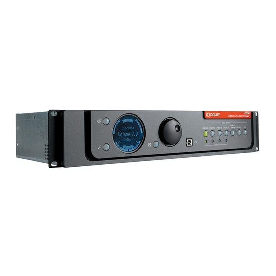
Digital Cinema Processor Input Select Input Select Multi-Ch Multi-Ch Digital 1 Digital 1 Digital 2 Digital 2 Digital 3 Digital 3 Digital 4 Digital 4 Analog Analog NonSync Mic. Valid Figure 1-1 CP750 Front Panel ® Dolby CP750 Digital Cinema Processor Manual... -
Page 15: Front-Panel Menu Navigation Buttons
Front-Panel Status Display Day‐to‐day operation of the CP750 is performed through interaction with the front‐panel status display shown in Figure 1‐2. Processing Display The top line displays the processing being applied to the audio. The supported processes are: • Dolby Pro Logic • Dolby Pro Logic II • Dolby Digital • Dolby Digital Surround EX • Discrete • Dolby 7.1 Volume Display The main fader level is displayed as a two‐digit number. As with previous generations of Dolby cinema processors, a fader setting of 7.0 (0 dB) is the nominal correct operating level. 7.0 matches the level used during production of the motion picture. Input Display The bottom line of the display shows the type of audio being input. Meter Display The circle of lights surrounding the display text serves as channel meters when the CP750 is in use. ® Dolby CP750 Digital Cinema Processor Manual... -
Page 16: Mute Button
Left Processing Volume Input Subwoofer Left Surround Right Surround Figure 1-2 Front-Panel Display 1.2.3 Mute Button Pressing the mute button shown in red in Figure 1‐1 fades the audio output to all channels without disturbing the current main fader setting. Fade‐in and fade‐out speeds are separately adjustable from 0.2 to 5 seconds, using the PC setup software. The mute button flashes red when activated. 1.2.4 Main Fader Knob Use this knob to adjust the sound level. A fader reading of 7.0 is the nominal correct operating level. The main fader knob rotates continuously with no end stops. The knob is also used to adjust parameters during setup operations. When the fader knob is rotated between readings of 0 and 4.0, the output level changes in 20 dB steps between –90 and –10 dB. When the fader knob is rotated between readings 4.0 and 10, the output level changes in 3.33 dB steps between –10 and –10 dB. Figure 1‐3 shows the characteristic graph. ® Dolby CP750 Digital Cinema Processor Manual... -
Page 17: Usb Port
Digital 2 DIGITAL 2 Selects the input signal from the 1xAES connector (BNC) Digital 3 DIGITAL 3 Selects the input signal from the 1xAES connector (S/PDIF optical) Digital 4 DIGITAL 4 1.2.7 Valid Input LEDs Each digital input push button has a green LED located beneath it. These LEDs light Valid up when the CP750 detects a valid signal on the respective input, whether or not the input is selected. and have valid signals in Figure 1‐1. Digital 1 Digital 4 ® Dolby CP750 Digital Cinema Processor Manual... -
Page 18: Analog Inputs
LISTED AUTOMATION ANALOG INPUT Dolby, Pro Logic and the double-D symbol LINK NOT ETHERNET DIGITAL 2 DIGITAL 3 DIGITAL 4 PROFESSIONAL AUDIO are registered trademarks of Dolby Laboratories. EQUIPMENT 4J06 Figure 1-4 CP750 Rear Panel The CP750 rear panel, shown in Figure 1‐4, includes the following components: • AC input. •... -
Page 19: Ac Input
Ethernet Port This is an illuminated RJ‐45 10/100 Base‐T Ethernet port with activity LEDs, which provides an interface to a Dolby Digital Cinema network and also ASCII string commands over TCP to port 61408. You can also use this port for setup software and firmware upgrades. 1.3.4 RS-232 Serial Port You can use this port for serial control using ASCII string commands. The equipment connected to this port should have its serial port set to 9600 baud, no parity, 1 stop bit. Use a pin‐to‐pin serial cable. The same control functions are available through the Ethernet port. 1.3.5 Remote Connector This is not an Ethernet connection, but an Ethernet cable is used to connect to the Cat. No. 868 Remote Fader. 1.3.6 4xAES IN Connector This 25‐pin female D‐connector, linked to the button, receives four AES/EBU Digital 1 streams. The four AES input signals must be time aligned with each other. Typically, this input connects to a Dolby Digital cinema server. It accommodates PCM audio at 96, 48, and 44.1 kHz, and 32 kHz (16, 20, and 24 bits) and Dolby Digital at all data rates and sample rates. The decoding of Dolby Digital is restricted to the first AES3 channel pair. This connector has a floating ground. ® Dolby CP750 Digital Cinema Processor Manual... -
Page 20: Automation Connector
48, 44.1, and 32 kHz (16, 20, and 24 bits) and Dolby Digital at all data rates and sample rates. 1.3.10 NonSync Input Connector Two RCA jacks labeled and that accept 3 V maximum input. 1.3.11 Aux Out Connectors These analog output represents channel pair 7/8 of the 4× AES input. For the top output (labeled ), the source is channel 7 of the 4× AES input. No equalization or level control is applied. For the lower output (labeled ), the source is channel 8 of the 4× AES input. No equalization or level control is applied. These analog output connectors represent either channel pair 7/8 of the 4× AES input or the input present on the input, depending on the selected output configuration and Digital 2 the setting on the tab. HI/VI-N Options General Settings ® Dolby CP750 Digital Cinema Processor Manual... -
Page 21: H/I Out Connector
1.3.14 Mic. Input This input is for use with a balanced output microphone. Phantom power is provided, and can be turned on and off under software control using the setup software. 1.3.15 Main Audio Output Connector This connector is an 8‐channel analog output (L, C, R, Ls, Rs, SW, Bsl, and Bsr), which is present on a male 25‐pin D‐connector (300 mV reference level). Bsl and Bsr channels are required for Dolby Digital Surround EX ™ installations. For other installations these channel can be configured to represent channel pair 7/8 of the 4xAES input. These mutually exclusive options are configured in the setup software. 1.3.16 Multi-Channel Analog Input Connector This connector is an 8‐channel analog input (L, C, R, Ls, Rs, SW, Bsl, Bsr) designed to receive 300 mV (ref) inputs from external sources and inputs on a female 25‐pin D‐connector. These inputs are balanced and floating, but the common mode voltage must not exceed ±6 V peak. Questions or Feedback If you have questions or comments about this document, please contact technical publications. ® Dolby CP750 Digital Cinema Processor Manual... - Page 22 If you have technical questions about this product/technology, please contact technical support.
-
Page 23: Chapter 2 Installation
• BNC digital inputs: These are transformer isolated and their grounds can be 1xAES IN +10 V peak from the chassis ground. • D‐connector digital inputs: These are transformer isolated and their grounds 4xAES can be +10 V peak from the chassis ground. Note: The RS‐232 input ground is connected to the CP750 chassis ground and is not floating. Digital Audio Inputs There are two professional interface standards for digital audio transmission: AES/EBU (also known as AES3) and AES‐3id. These methods stream the same digital data and professional audio header information over copper conductor links, but use different types of conductors and connectors. AES/EBU uses a balanced connection (two conductors plus shield) with a characteristic input impedance of 110, a nominal peak‐to‐peak signal level of 5 V, and, most commonly, XLR connectors. The typical maximum transmission distance is 100 meters (328 feet). AES‐3id uses an unbalanced connection (one signal conductor plus shield) with a characteristic input impedance of 75, peak‐to‐peak signal level of 1 V, and BNC (“push and twist”) connectors. The typical maximum transmission distance is 1,000 meters (3,280 feet). Professional digital audio equipment typically uses the AES/EBU method because balanced operation yields superior noise immunity, as it does with analog audio signals, and because XLR connectors are the standard on analog professional audio equipment. Professional video equipment typically uses the AES‐3id interface, with BNC connectors. As with XLR connectors on professional audio equipment, the adoption of BNC connectors for the audio on professional video equipment stems from their use for the video signal. Also, the unbalanced AES‐3id signal can connect to more than one piece of ® Dolby CP750 Digital Cinema Processor Manual... -
Page 24: Consumer Interface Standards For Digital Audio
For conversion between the AES‐3id and S/PDIF formats, you can use high‐quality RCA‐to‐BNC adapters because the cable and impedance are both the same (75). For conversion between the AES/EBU and AES‐3id or AES/EBU and S/PDIF formats, a simple and economical method uses inline transformers. These devices perform the necessary impedance and balanced/unbalanced conversion. Table 2‐1 shows some examples of suitable adapters. The unbalanced connector in these examples is BNC. You can add BNC‐to‐RCA adapters for connecting to consumer S/PDIF connections. The following units use passive circuitry. Table 2-1 Examples of Available Balanced/Unbalanced Adapters ® ® Adapter Type Neutrik Canare XLR female 110 in to BNC female 75 out NA‐BF BCJ‐XJ‐TRA BNC female 75 in to male XLR 110 out NA‐BM BCJ‐XP‐TRA Higher‐priced units incorporating active circuitry are also available. These offer additional features such as multiple inputs, inputs for optical connections, and multiple outputs. ® Dolby CP750 Digital Cinema Processor Manual... -
Page 25: Mounting The Cp750
To ensure good ground contact, install a star washer on at least one (and preferably all) rack‐mounting screws as shown in Figure 2‐1. This will also aid in the prevention of electrical noise problems. Figure 2‐1 Figure 2-1 Star Washers and Rack-Mounting Screws Proper shielding and termination of cables and cable assemblies are also very important. Follow the methods shown in the wiring diagrams. Connections To connect the CP750 to your auditorium equipment, refer to Figure 2‐2. For proper operation in locations where there is considerable interference, strictly adhere to the cable types, lengths, and pin assignments. Shields must connect only to the chassis and should not be paralleled with the negative side of inputs or outputs. Connector pinouts are listed in Section 8.2. Fuse Information The CP750 uses a universal‐switching power supply that handles the full range of nominal mains voltages between 100 and 240 VAC, and any frequency between 50 and 60 Hz. If a power supply fuseinside the unit blows, do not attempt to replace it. Instead, contact Dolby Laboratories. The fuse on the unit rear panel is intended to be replaceable. If it blows, replace it with a fuse of the same type. ® Dolby CP750 Digital Cinema Processor Manual... -
Page 26: Mains Power Wiring
Installation Mains Power Wiring In some countries, the primary mains cable may not have a connector fitted. Nonterminated leads must be properly wired to an approved mains connector in accordance with the following international code: • Brown wire: live or hot • Blue wire: neutral • Green wire: mains ground Warning: If you are uncertain about the wiring of your AC mains outlet, do not use it. Consult a qualified electrician. Cable Diagram The cable diagram for the CP750 rear panel is shown in Figure 2‐2. ® Dolby CP750 Digital Cinema Processor Manual... -
Page 27: Figure 2-2 Cp750 Inputs And Outputs
Installation Cable Diagram Figure 2‐2 Figure 2-2 CP750 Inputs and Outputs ® Dolby CP750 Digital Cinema Processor Manual... -
Page 29: Chapter 3 Installing, Launching, And Connecting The Setup Software
Begin by installing the software on a PC, which you can connect to the CP750 with a USB cable. System Requirements The CP750 setup software runs on Microsoft ® Windows ® XP and Windows Vista ® . Installing the Software To install the CP750 setup application: Open the folder and run . This file is named with CP750 Setup CP750Setup_x_x_x.exe the current software version number. The installer opens displaying the screen shown in Figure 3‐1. Figure 3‐1 Figure 3-1 Installer Welcome Screen Select the desired language. Follow the screen prompts. ® Dolby CP750 Digital Cinema Processor Manual... -
Page 30: Connecting The Hardware
• You can connect directly to the connector on the unit rear panel. If your Ethernet laptop supports Gigabit Ethernet, use a standard Ethernet cable. Otherwise, use a crossover cable. • You can connect a pin‐to‐pin serial cable to the connector on the unit rear RS-232 panel. Launching the Setup Application To launch the CP750 setup application, click the Start button and scroll to Programs. In the Dolby folder, double‐click Dolby CP750 Setup. The Dolby ® CP750 setup window appears, as shown in Figure 4‐1. Connecting to a Local or Remote Device You can use the setup software menu, shown in Figure 3‐3, to connect to a local or a Action remote device. ® Dolby CP750 Digital Cinema Processor Manual... -
Page 31: Figure 3-3 Action Menu
Connecting to a Local or Remote Device Figure 3‐3 Figure 3-3 Action Menu These options allow you to connect to a CP750 that is either connected to your PC (local device) or connected to an Ethernet network (remote device). If you select Connect to remote device the system prompts you to enter an IP address. You must change TCP/IP properties of your laptop to communicate properly with the CP750 when connecting the setup software to a CP750 using a PC Ethernet connection. We recommend the following TCP/IP settings to enable your PC to communicate with a CP750 using its default setting. IP address: 192.168.1.200 Subnet mask: 255.255.255.128 Default gateway: 192.168.1.129 Note: The CP750 default IP address (for connecting) is 192.168.1.136. ® Dolby CP750 Digital Cinema Processor Manual... -
Page 33: Chapter 4 Configuring The Cp750 Software
Chapter 4 Configuring the CP750 Software Note: After you load a saved configuration file, you must adjust the Network tab settings to reflect the correct auditorium. Loading a Saved Configuration File is a convenient way to make these changes quickly. Using the Application Tabs to Configure a CP750 Each setup application tab controls a different part of the application function. They are discussed separately in the following sections: • Profile Tab: Lets you enter identifying information that is important for service calls and technical support. • Network/Time Tab: Lets you specify unit addresses and connections • General Settings: Lets you define a power‐on mode, a subwoofer filter frequency, and a surround delay for the CP750. • Input Settings: Lets you define attributes and processing for each input. • Alignment: Lets you optimize the sound in the auditorium. This important topic is described in detail in Chapter 4.1.1 Profile Tab When you launch and connect the CP750 setup software, the application opens with the tab active, as shown in Figure 4‐1. Profile ®... -
Page 34: Network/Time Tab
Digital Cinema System • : Identifying information for your projector. Digital Cinema Projector • : The identifying text you enter here is repeated as the titles of the Input Descriptions tab. Input Settings Tip: Assigning clear names to the digital inputs is an easy way to prevent input selection errors. The tab displays the current network settings, but you can modify them only on the Profile tab. Network/Time 4.1.2 Network/Time Tab The tab, shown in Figure 4‐2, lets you configure the CP750 Ethernet settings Network/Time and time and date settings. The host name and IP address are echoed, read‐only, on the tab. Network Profile configuration and status are also available though the ASCII control interface. ® Dolby CP750 Digital Cinema Processor Manual... -
Page 35: Figure 4-2 Network/Time Tab
Using the Application Tabs to Configure a CP750 Ethernet Settings By default DHCP is turned off, and entries follow the Dolby ® Digital Cinema private network address naming convention in which the third octet indicates the auditorium number: • : CP750 Host Name xxxxx • : 192.168. .136 IP Address • : 255.255.255.128 Subnet Mask • : 192.168. .129 Default Gateway If you are using the Dolby TMS you need only enter the auditorium number in the third triad of the and fields. IP Address... -
Page 36: General Settings
4.1.3 General Settings This tab, shown in Figure 4‐3, lets you set four system attributes: • Power‐On Mode • Surround Delay • Main Output Configuration and HI/VI‐N Options • Mute Duration Figure 4‐3 Figure 4-3 General Settings Tab Power-On Mode The Power‐on Mode selects the input that is activated when the CP750 unit is powered on. You can select Last Setting, or any of the inputs. Surround Delay The setup application can calculate and set the General surround delay value based on theatre measurements entered here. Measurements may be entered in feet or meters. Click Feet or Meters to choose a unit of measure. Enter a Distance from screen to rear wall of theatre value between 0 and 200. Enter an Average distance between left and right Surround channels value between 0 and 140. Click Calculate. ® Dolby CP750 Digital Cinema Processor Manual... -
Page 37: Input Settings
Using the Application Tabs to Configure a CP750 The General value is adjustable from 0 to 150 ms in 1 ms steps. The display shows a marker every 10 ms. After you set the general surround delay for digital material, set the Pro Logic/Pro Logic II value which is applied to analog material. The minimum value for this slider is 20 ms because this value should always be 20 ms higher than the General value. Main Output Configuration and HI/VI-N Options You can choose either of two options: • 5.1 Output Configuration (No BSL or BSR Installed): Selecting this option causes the audio on channels 7 and 8 of the 4× AES input to be routed to the Aux Output connector on the rear panel of the CP750 to support HI/VI‐N in the DCP. • Dolby Surround 7.1 /Surround EX Output Option (BSL and BSR Installed): Selecting this option enables 7.1‐channel support in the CP750, if the auditorium has back surround speakers installed. When this option is selected, you can choose to: • Disable 7/8 Aux Out: Selecting this option disables the output on the rear Aux 7/8 panel of the CP750. • Route Digital 2: Selecting this option causes the CP750 to route digital audio present on the ... -
Page 38: Figure 4-4 Digital Input 1 Tab
Global Audio Delay • Mute Main Bsl/Bsr Output Pins • Fader Preset • PCM Channel Assignment • PCM Decode Mode • PCM Processing Mode • Dolby Digital Decode Mode • Dolby Digital Dialogue Normalization Global Audio Delay The Global Audio Delay field specifies an audio delay in addition to the CP750 decoding delay of approximately 13 ms for 4× AES PCM. Use this function to synchronize the audio with the video from digital cinema projectors, which add a video processing delay. Use the up and down arrows to set the Global Audio Delay between 0 250 ms. This delay value is set independently for each digital input. Note: Systems that use an external video scaler may add another decoding delay. Mute Main Bsl/Bsr Output Pins Choose Enable to mute these pins if your auditorium does not use them. ® Dolby CP750 Digital Cinema Processor Manual... - Page 39 Using the Application Tabs to Configure a CP750 Fader Preset To use the Fader Preset feature, choose Enable and indicate a value on the slider. This ensures that inputs play at correct values each time they are selected. PCM Channel Assignment The analog audio output channels (L, R, C, LFE, Ls, Rs) are always fixed and hardwired to a cinema processor. However, when the input‐channel mapping of a PCM bitstream is not a default SMPTE configuration (L/R, C/LFE, Ls/Rs), you must reassign the input channels to match the hardwired audio outputs. For channel reassignment, the surround delay and the LFE filter are always tied at the output, and therefore cause no problem. To reassign the input channels, use the drop‐down Assigned To menu for each of the AES Input channels or click one of the three preset buttons (L/R C/Sw Ls/Rs; L/C R/Ls Rs/Sw; or L/Ls C/Rs R/Sw). To activate your changes, click the Apply changes button. To cancel your changes, click the Discard changes button. PCM Decode Mode You can select one of four surround channel processing options: • None • Pro Logic • Pro Logic II • Surround EX • Dolby Surround 7.1 PCM Processing Mode You have three choices of mode:...
-
Page 40: Digital Inputs 2, 3, And 4
Digital Inputs 2, 3, and 4 The options available on these three tabs are identical. Figure 4‐5 shows the Digital Input 2 tab. The tab titles are repeated from the input descriptions on the Profile tab. Figure 4‐5 Figure 4-5 Digital Input 2 Tab For these inputs you can configure: • Global Audio Delay • Fader Preset • PCM Decode Mode • PCM Processing Mode • Dolby Digital Decode Mode • Dolby Digital Dialogue Normalization The options for Global Audio Delay, Fader Preset, PCM Processing Mode, Dolby Digital Decode Mode, and Dolby Digital Dialogue Normalization are identical to those on the Digital Input 1 tab. ® Dolby CP750 Digital Cinema Processor Manual... -
Page 41: Analog Input
Using the Application Tabs to Configure a CP750 PCM Decode Mode There are three decoding options for two‐channel PCM streams: • None • Pro Logic • Pro Logic II 4.1.7 Analog Input Figure 4‐6 shows the Analog Input tab. Figure 4‐6 Figure 4-6 Analog Input Tab On this tab you can set: • Global Audio Delay • Mute Main Bsl/Bsr Output Pins • Fader Preset • PCM Channel Assignment •... -
Page 42: Mic Input
• Format 70 Mono CS • Format 71 Mono C • Format 73 Pro Logic LCR • Format 74 Pro Logic ® with no subwoofer • Format 75 Pro Logic with a subwoofer You can also set an Input Trim using the slider. Figure 4‐7 Figure 4-7 Nonsync Input Tab 4.1.9 Mic Input On the Mic Input tab, shown in Figure 4‐8, you can choose: • Global Audio Delay • Fader Preset The options operate identically to those on other tabs. The PCM Channel Assignment field allows you to assign the microphone input to either the Center channel or the Surrounds. In the Phantom Power field, you can enable phantom power to the microphone as needed. ® Dolby CP750 Digital Cinema Processor Manual... -
Page 43: Saving Settings In A Configuration File
.dlb Chose Save in the File menu as shown in Figure 4‐9, browse to the location on your PC where you want to save the file, enter a file name, and click Save. Figure 4‐9 Figure 4-9 Selecting Save in the File Menu To modify an existing . file and save it under a different name, open the file, then select in the menu. Save As File Loading a Saved Configuration File A CP750 can be restored from an existing configuration file. .dlb To do so, choose Open in the File menu of the setup application, browse to the desired . file on your PC, and open it. ® Dolby CP750 Digital Cinema Processor Manual... -
Page 44: Using Expert View
Using Expert View When you choose Expert View on the Window menu, all the CP750 parameters and command strings are available as shown in Figure 4‐11.You can modify a parameter highlighted in green by double clicking it and typing a new value. To return to the tab display, reselect Expert View. Figure 4‐11 Figure 4-11 Expert View Window Updating the CP750 Firmware To update the CP750 firmware: Obtain the latest version of the CP750 setup application from Dolby Laboratories and install it on your PC. Obtain the update file from Dolby Laboratories and copy it to your PC. .dlb Connect your PC to the USB port on the CP750 front panel. Click the tab to begin the update process. The tab is shown in Software Update Figure 4‐12.. ® Dolby CP750 Digital Cinema Processor Manual... -
Page 45: Figure 4-12 Dolby Software Update Screen
Updating the CP750 Firmware Figure 4‐12 Figure 4-12 Dolby Software Update Screen Click to find the update file on your PC, then click Browse .dlb Open Click Update. After a few seconds, a progress bar displays the status of the update process. When the process is completed, the CP750 automatically reboots with the updated firmware. ® Dolby CP750 Digital Cinema Processor Manual... -
Page 47: Chapter 5 Playing Dolby Surround 7.1 Audio
Playing Dolby Surround 7.1 Audio Preparation of a Dolby ® CP750 Digital Cinema Processor for Dolby Surround 7.1 audio requires four steps: Upgrade the cinema processor and server software, if necessary. Make any necessary changes to the AES audio cable connecting the server and processor. Manually change the audio output of the DSP100 Dolby Show Player (if your auditorium uses one). If necessary, make changes to surround speaker wiring to accommodate Dolby Surround 7.1 audio. This chapter provides details of the setup processes for auditoriums using Dolby cinema servers. If your auditorium does not contain a Dolby cinema server, contact the server manufacturer to ensure you have 16‐channel playback capability and to obtain the necessary digital audio pinouts of the server. Sixteen ‐channel playback is required because the Back Surround Left (Bsl) and Back Surround Right (Bsr) audio channels are carried on channels 11 and 12 (AES pair 6). Required Software The Dolby Digital Cinema server requires, at a minimum, software release v.4.2.1. The CP750 requires software version 1.2.6.5 or later. Install all required software updates before proceeding. Cable Connections Each combination of server and sound processor has its own cabling requirements. Refer to the section that matches your equipment. The combinations are: • Connecting a DSP100 to a CP750 • Connecting a DSS200 to a CP750... -
Page 48: Connecting A Dsp100 To A Cp750
Connecting a DSP100 to a CP750 The pinout is listed in Table 5‐1. Table 5-1 DSP100 Output Connector Pinout Description Description AES common 14 Channels 1/2 + Channels 1/2 − AES common Channels 3/4 + 16 Channels 3/4 − AES common 17 Channels 5/6 + Channels 5/6 −... -
Page 49: Connecting A Dss200 To A Cp750
Connecting a DSS200 to a CP750 Dolby Surround 7.1 requires changes to the wiring of the DSS200 output cable. The pinout is listed in Table 5‐2. Table 5-2 DSS200 Audio Output Pinout Description Description AES common Channels 1/2 + Channels 1/2 − AES common Channels 3/4 + Channels 3/4 − AES common Channels 5/6 + Channels 5/6 − AES common Channels 7/8 + Channels 7/8 − AES common AES common Channels 9/10 + Channels 9/10 − AES common Channels 11/12 + Channels 11/12 − AES common Channels 13/14 + Channels 13/14 − AES common Channels 15/16 +... -
Page 50: Update Surround Speaker Wiring
Enter is highlighted gives you the option of changing to channels 9–16. Channel Mapping Use the down arrow key to select . Highlight and press the key once. 9–16 Enter Your DSP100 is now configured to pass up to 16 channels of audio. Update Surround Speaker Wiring If your auditorium is wired to support Dolby Digital Surround EX™ audio, you do not need to make any additional changes. If your auditorium is not wired to support Dolby Digital Surround EX, you may need to make changes to the wiring and add amplifiers, as described in the CP650 Dolby Digital Surround EX Connections installation note. The sound pressure level is 82 dB for each. HI and VI-N Channels With the introduction of Dolby Surround 7.1, AES pair 4 inputs to the CP750 are required for routing the Bsl and Bsr channels into the cinema processor. If these CP750 inputs are currently being used for routing hearing impaired (HI) or visually impaired narration (VI‐N, also known as audio description) channels, an external digital‐to‐analog (D/A) converter will be required for the HI/VI‐N channels. You may use aftermarket cables or adapters to fit your installation. HI/VI‐N channels may be placed in AES pair 4 (channels 7/8) or AES pair 8 (channels 15/16) depending on territory or the configuration of the digital cinema package (DCP). For the DSP100 and CP750 combination, when configured for Dolby Surround 7.1 playback, BNC connector 4 on the rear of the DSP100 will be accessible to retrieve AES pair 8. Dolby Laboratories offers a 7.1 cable to connect the DSP100 to the CP750; the cable package also includes a dongle connector to access HI and VI‐N on AES pair 4. For the DSS200 and CP750 combination, when configured for Dolby Surround 7.1 playback, all audio connections are made on the 25‐pin D‐connector port. A custom cable or breakout board can be made to retrieve the AES pair 8 from the output of the DSS200 on pins 25 and 13, as referenced in Table 5‐2. AES pair 4 from the output of the DSS200 is on ... -
Page 51: Managing Decode Mode Switches With V.4.2.0 Software
cue. This reselects Dolby CP750 Input: Digital 1 Surround 7.1 mode. For shows containing 5.1 discrete content only, always place a CP750 Decode Mode: cue after is selected to ensure that 5.1 discrete monitoring is used. Discrete Digital Input 1 5.11 Using Software to Configure the CP750 for Dolby Surround 7.1 Using the CP750 PC setup software version 1.2.4.3 or later, connect to your CP750 and select the general settings tab. In the section, click Main Audio Output Configuration Bsl/Bsr (shown in Figure 4‐3) to select it. This configuration is required for Dolby (Surround EX) Surround 7.1 and Dolby Digital Surround EX decode modes, and applies the required ... -
Page 52: Setting The Decode Mode Of The Cp750
Dolby Surround 7.1 Note: The decode mode set here is applied whenever is selected. Digital Input 1 Ensure that the box is cleared, not checked. These channels Mute Main Bsl/Bsr Output Pins are required. 5.14 Manually Configuring the CP750 for Dolby Surround 7.1 The decode mode can also be set manually using the front‐panel interface. Digital Input 1 Push the menu button on the front panel of the CP750 (shown circled in Figure 5‐3) to place the unit into editing mode. Figure 5‐3 Figure 5-3 CP750 Front-Panel Menu Button Once in editing mode, you will be presented with the decode mode choices. Rotating the ... -
Page 53: Serial And Ethernet
is Digital Input 1 selected. Figure 5‐5 Figure 5-5 Dolby 7.1 Decode Mode 5.15 Serial and Ethernet Table 5‐3 lists the string parameters needed for ASCII control over serial or Ethernet. Table 5-3 ASCII String Commands CP750 ASCII String Parameter Action 5.1 discrete decode mode cp750.sys.pcm_2_channel_decode_mode_1 lr_discrete Dolby Surround 7.1 decode cp750.sys.pcm_2_channel_decode_mode_1 4_discrete_sur mode ... -
Page 55: Chapter 6 Aligning The Auditorium
Checking Theatre Equipment Thoroughly check the loudspeakers and power amplifiers for any sources of poor performance, using the checklists below as a guide. 6.1.1 Speakers • Check loudspeaker cable condition and confirm that the cables are the correct gauge for the impedance of the speakers and the length of the run. • Check that the speakers are connected to the correct power amp channel. • Check for leaks in the low‐frequency driver cabinet which may sound like rattles. • Check for loose bolts or other hardware. • Check the speakers with an ohmmeter. If one channel requires markedly more equalization than the other, or if one speaker overloads at lower levels than the other speakers, an open driver circuit could be the cause. In systems with pairs of drivers, one voice coil of the pair may be open but the system will still function. • Check for missing drivers or other components. • Verify that crossover settings matching the type of drivers in use and the acoustics of the theatre. The high‐frequency driver level control must be set for the best possible frequency response before you attempt any equalization. This is especially true if the system uses active crossovers with biamp equipment. • Check for proper polarity between the low‐ and high‐frequency drivers, and between the channels. • Ensure that the speakers are correctly aimed into the auditorium, and that they are not obstructed by the screen frame, struts, or other objects. ® Dolby CP750 Digital Cinema Processor Manual... -
Page 56: Amplifiers
6.1.3 Air Conditioning If air‐conditioning noise is audible in the theatre, minimize it by: • Lubricating the motor and fan bearings • Adjusting belts and drives • Cleaning the filters or screens on the air‐conditioning returns Microphone Placement Position a microphone multiplexer in the center of the auditorium listening area. Place each microphone in the reverberant field rather than in an area that receives the most direct energy from the speakers. In addition, avoid perfect symmetry. Arrange the microphones so that they do not form a square or rectangle parallel to the sides of the room. Take care not to place any of the multiplexing microphones on the auditorium center line. Standing waves and nodes can cause measurement errors. During final SPL calibration, microphone number 1 should be placed two‐thirds of the distance from the front speakers to the rear, at the exact side‐to‐side center of the room, approximately five feet above the floor level, and rotated 45 degrees upward toward the screen. (Some multiplexer microphones are designed to be pointed directly at the ceiling.) Placement of this microphone is important for output level adjustments. Figure 6‐1 Figure 6-1 Microphone Placement for Equalization If a single microphone is used, which we do not recommend, use the number 1 position detailed above, but place it slightly off center during equalization. ® Dolby CP750 Digital Cinema Processor Manual... -
Page 57: Initial Setup
Mic. Input rear panel. Note: Many microphones require phantom power, which can be enabled in the CP750 setup software. Initial Setup Prepare for the alignment process with the following steps: Set all the gain controls on all power amplifiers to known, repeatable settings. The preferred setting for most amplifier gain controls is the maximum. If a different setting is required in order to optimize the noise performance of the system, the controls should be locked in position or marked clearly. Caution: The following process causes the CP750 to output pink noise to the power amplifiers. The CP750 output levels may be set too high. If you are unsure of the settings on your unit, turn off the power amplifiers before calibrating SPL. Then, select and observe the present output level adjustment settings. Set up your crossovers if present. Apply power to the CP750. Launch the CP750 Setup Software, connect to the unit, and click Alignment. The software displays a warning that entering alignment mode will disturb auditorium audio. Click Continue in the warning tab that appears to begin the auditorium alignment process. The Room Levels tab appears active. Room Levels shows a summary of current settings, allows you to calibrate the internal SPL meter, allows you to choose a channel with which to work, or to adjust any channel’s level with a slider. Each increment of the displayed relative number from a value of 1 to 127, represents an increment of approximately 0.25 dB of range adjustment. Figure 6‐2 shows an example of the tab before the SPL is calibrated. ® Dolby CP750 Digital Cinema Processor Manual... -
Page 58: Calibrating The Internal Spl Meter
Aligning the Auditorium Figure 6‐2 Figure 6-2 Alignment Tab Showing Room Levels Calibrating the Internal SPL Meter You must calibrate the internal SPL before proceeding with alignment. To start the process, click C under Signal Generator Enable to activate the Center channel. Select Pink Noise from the Signal Mode drop‐down list. Pink noise is sent to the Center channel speaker. Note: The CP750 is shipped from the factory with the Mic. Input level control set to the minimum. Check the microphone level to be sure it appears in the target range as shown in Figure 6‐2. If necessary, adjust the on the rear panel of the CP750 until the level is within Mic. Gain the target range. ® Dolby CP750 Digital Cinema Processor Manual... -
Page 59: Initial Output-Level Adjustment
6.2. Enter the measured value into the Measured Value field. Wait while the system automatically calibrates to the room reading. The calibration is retained in CP750 memory and can be used in future alignments. However, it is advisable to recalibrate the system when rearranging microphones because the sound pressure level varies slightly with microphone placement. Initial Output-Level Adjustment Next, adjust each channel slider to make sure the pink noise is audible and to achieve a reasonable sound pressure level in the auditorium. It is not necessary to set exact levels because the levels will change slightly during equalization. Exact output level adjustment is performed after equalization. Note: For this and all other adjustments using sliders, use the slider to get close to the optimal value. Use the up and down arrow keys to make fine adjustments. 6.5.1 Setting Main Channel Levels When the CP750 is first installed, you must repeat these steps for each channel. Values are adjusted on the Channel Tune tab after a channel is chosen. Figure 6‐3 shows an example with the Center channel selected. Click a channel radio button to make it active and lock pink noise to it. Check the level indicated underneath the Channel Level slider, and move it up or down until the measured level reads 85 dB. Repeat steps 1 and 2 for the R and L channels, setting the Channel Level to 85 dB. Repeat steps 1 and 2 for the Rs, Ls, Bsr, and Bsl channels, setting each to read 82 dB. ® Dolby CP750 Digital Cinema Processor Manual... -
Page 60: Subwoofer Levels
Aligning the Auditorium Figure 6‐3 Figure 6-3 Channel Tune Tab Showing the Center Channel 6.5.2 Subwoofer Levels After the last surround channel is adjusted, click LFE to calibrate the subwoofer. Pink noise is now present on the subwoofer channel only (140 Hz bandwidth for EQ and level setting screens). The LFE has distinct options that appear on the Channel Tune tab, as shown in Figure 6‐4. ® Dolby CP750 Digital Cinema Processor Manual... -
Page 61: Room Equalization
Figure 6‐4 Figure 6-4 Channel Tune Tab Showing LFE EQ Initial subwoofer level setting uses a blue reference line displayed on the LFE Channel Tune tab, established from the Center channel pink‐noise level. Using the Channel Level slider, adjust the level, moving the average subwoofer RTA display to match the reference line on the screen as closely as possible. Final subwoofer level adjustments for both digital and Dolby ® Pro Logic ® signal paths are carried out later, after the room is equalized. Room Equalization Room equalization is performed using the RTA built into the CP750. The desired result is a frequency response that closely matches the “x‐curve” overlay (SMPTE 202M‐1998). Results achieved within ±3 dB of the x‐curve are considered within tolerance of the specification. Small diameter, pressure calibrated microphones are preferred for accuracy over large diameter types. Use of a microphone multiplexer will accommodate spatial averaging of different positions within the room, which is recommended for best results. Follow this sequence: Perform coarse adjustments of each channel using the Bulk EQ Bass and Treble sliders. Perform fine adjustments of each band using the 27‐band one‐third‐octave equalizer. Perform LFE channel equalization by setting the frequency, Q (width), and level of cut, using the single‐band parametric equalizer. ® Dolby CP750 Digital Cinema Processor Manual... -
Page 62: Setting Bulk Eq
Using EQ Assist The EQ Assist feature automatically adjusts the frequency response to the x‐curve. Use this feature with care since it adjusts adjacent bands as necessary (even to extremes) to achieve the exact x‐curve. The EQ Assist feature does not adjust to room anomalies as a human operator can, avoiding overcompensation in any frequency bands. Note: If you use this feature, be sure to use it after adjusting the bass and treble bulk EQ. To prevent overcompensation for possible speaker problems, the 20, 25, 30, 40, 50, and 63 Hz, as well as the 12.5 and16 kHz, bands are not automatically adjusted. You must adjust these bands manually. 6.6.3 Making Fine Adjustments to Individual Bands Observe adjacent band effects when adjusting individual frequencies. Be aware of frequency bands that are very different from neighboring bands, and use caution so as not to overcompensate. (Major differences could be the result of a room node at the particular microphone location.) Adjust each frequency band as necessary to achieve a smooth EQ with results nearing the x‐curve overlay. The goal is to achieve (or come close to) the x‐curve without overcompensating. Remember that the SMPTE tolerance is ±3 dB, although closer results are often easily achieved. 6.6.4 Adjusting LFE Channel EQ Begin with zero cut and observe the worst peak within the spectrum. Adjust the Center slider until the frequency matches the peak, and then adjust the Cut to flatten that region. Adjust the Q (width) and Cut, until the smoothest response is achieved. ® Dolby CP750 Digital Cinema Processor Manual... -
Page 63: Final Output-Level Calibration
Click to check other Q values for the flattest possible frequency response. Final Output-Level Calibration Once room equalization is complete, the sound pressure level in the theatre can be set accurately. 6.7.1 Main Channels If a microphone multiplexer is being used in your auditorium, move Mic 1 to room center two‐thirds back from the screen. Click the Room Levels tab to activate it. Using the sliders, set L, C, R to 85 dB, and the surround channels to 82 dB. Note: Because the sound pressure level calibration was performed earlier, a recalibration is not required unless the microphone placement has changed. Repeat the steps in Section 6.4 if necessary. 6.7.2 Subwoofer Channel Level Whereas the final sound pressure levels of the main audio channels are ideally adjusted with a single microphone two‐thirds back from screen at room center, the subwoofer channel level is best adjusted with the microphone multiplexer cycling (if available). First complete the center channel equalization and level adjustment. On the Channel Tune tab, click LFE to make it the active channel and select Pink Noise as the Signal Mode. Use the slider and arrow keys to achieve an average level of +10 dB as indicated on the spectrum analyzer. This is the “digital” level, which is always set 10 dB higher than the Center channel. ® Dolby CP750 Digital Cinema Processor Manual... -
Page 64: Subwoofer Speaker Polarity Check
Choose a Filter Frequency to select the crossover point between your main speakers and the LFE. Use 50 Hz if your main speakers are full spectrum. Use 100 Hz otherwise. Click Phase Invert and watch the behavior of the filter frequency band. There should be a level decrease as soon as you click Phase Invert. If you do not see a decrease, the polarity of the subwoofer wiring is incorrect. Reverse the subwoofer speaker wire connections to correct it. The subwoofer polarity always resets to normal after completing this check. Phase Invert is a temporary setting for this test only. Final Sound Check Follow these steps to do a final equalization check of the auditorium. On the Room Levels tab, click Rotate under Signal Generator Enable. Choose Signal Mode Pink Noise to start pink noise. Pink noise is sent to each channel in turn, holding for five seconds at each channel. Note: Unlike the different levels used during alignment, the rotating pink noise is set to 85 dB for all channels during this test. Pressing <Enter> stops the pink noise from moving to the next channel. Pressing <Enter> again resumes pink‐noise rotation. Go to the auditorium and sit two‐thirds of the distance from the front speakers to the rear, and at the side‐to‐side center of the room. All channels should sound equally loud and have similar frequency response as the noise rotates. An SPL meter can be used to confirm accurate and equal level settings. Nonsync Level Adjustment You can adjust the Nonsync level on the Nonsync Input tab. Click the Nonsync Input tab to open it. Play a CD or other audio source on your nonsync device and adjust the slider in the setup software for the desired level in the theatre. If possible, select a recording that has a natural ambience, such as an orchestral work. ® Dolby CP750 Digital Cinema Processor Manual... -
Page 65: Noise Floor Optimization
Noise Floor Optimization 6.10 Noise Floor Optimization Noise Floor Optimization calculates and utilizes any available leftover capacity in each channel to improve the overall noise floor of the CP750. It operates by measuring the extent to which the unit uses the available headroom in the B‐chain, then boosts the overall gain to use all available headroom. The analog output level trims are then reduced by the amount of that boost, resulting in an optimally reduced noise floor. This adjustment also factors in the headroom available to the fader. Changes to the output trim values are transparent to the user, and no changes will be seen in the fader values in the setup software. Clipping may occur on high level signals if the fader is set above 7.0. ® Dolby CP750 Digital Cinema Processor Manual... -
Page 67: Chapter 7 Remote Control And Monitoring
Status Monitoring and Level Control in the Setup Software The virtual status monitor at the bottom of the setup software screens shown in Figure 7‐1 provides a user‐friendly interface. Its signal‐presence meter monitors the CP750 analog output. There is a virtual input selector for each CP750 input. Clicking any of these buttons activates the associated input. Each of the digital input virtual buttons has an associated virtual LED, indicating a valid signal. The software also echoes the state of the front‐panel display and fader. Any action available at the unit front panel can be executed through the remote software. Figure 7‐1 Figure 7-1 Virtual Status Monitor ASCII Control Full control of the CP750 is available through a set of ASCII commands and queries. No error correction (CRC), sync bytes, or protocol is applied to this interface. 7.2.1 Connections ASCII commands can be communicated over any of three ports: • The connector supports standard 9‐pin serial connections to PC serial ports RS-232 and other RS‐232 devices. It operates at 9600 baud with 8 data bits, 1 stop bit, no parity, and no flow control. It cannot be invoked while the serial data port is in use by the CP750 setup program. ® Dolby CP750 Digital Cinema Processor Manual... -
Page 68: Command Syntax
7.2.3 Command Set The set of serial commands is listed in Table 7‐1. Table 7-1 Normal Commands Parameter Name Valid Values Description and Comments 1.2.8.3 cp750.sysinfo.version 0, 1 cp750.ctrl.calc_surround_delays 0, 1 cp750.ctrl.default_params –100 to 100 cp750.ctrl.fader_delta 0, 1 cp750.ctrl.log_erase 0 to 2147483647 cp750.ctrl.log_uptime 0 to 2147483647 cp750.ctrl.reboot 0 to 170 cp750.sys.analog_global_delay ® Dolby CP750 Digital Cinema Processor Manual... - Page 69 0, 1 cp750.sys.fader_preset_a_enable 0 to 100 cp750.sys.fader_preset_m 0, 1 cp750.sys.fader_preset_m_enable 0 to 100 cp750.sys.fader_preset_n 0, 1 cp750.sys.fader_preset_n_enable n_a | off | on cp750.sys.full_ascii_ctrl 0, 1 cp750.sys.input_7_8_mute 0, 1 cp750.sys.input_7_8_mute_1 0, 1 cp750.sys.input_7_8_mute_a analog | dig_1 | dig_2 | dig_3 cp750.sys.input_mode | dig_4 | last | mic | non_sync [ip.ip.ip.ip nm.nm.nm.nm cp750.sys.ip_setting gw.gw.gw.gw| off|on hostname] 0, 1 cp750.sys.log_content 0 to 170 cp750.sys.mic_global_delay center | surrounds cp750.sys.mic_route 0, 1 cp750.sys.mute ® Dolby CP750 Digital Cinema Processor Manual...
- Page 70 0–147483647 cp750.sys.screen_distance 0–147483647 cp750.sys.serial_number 50 to 100 cp750.sys.subwoofer_filter 0, 1 cp750.sys.surround_boost 0, 1 0, 1 cp750.sys.surround_boost_a 0 to 150 cp750.sys.surround_delay cp750.sys.time 1 to 60 cp750.sys.time_update_int 4_discrete_sur | auto | invalid cp750.sys.two_channel_decode_mode | lr_discrete | n_a | prologic | prologic_2 | surround_ex Prints most recent log events dump_log_4096 Prints entire log dump_log help status Basic query format cp750.<category>.<parameter> ? exit ® Dolby CP750 Digital Cinema Processor Manual...
-
Page 71: Snmp
Other Standard MIBs Supported Sections RFC2006 MIP‐MIB, faRegistration group RFC 4292 IP‐FORWARD‐MIB ipForward, inetCidrRoutNumber, inetCidrRouteDiscards, inetCidrRoute table Table 7-4 V3 MIBS RFC 3411 SNMP‐FRAMEWORK MIB RFC 3412 SNMP‐MPD‐MIB RFC 3413 SNMP‐TARGET‐MIB, SNMP‐NOTIFICATION‐MIB, SNMP‐PROXY‐MIB RFC 3414 USM‐MIB RFC 2786 USM‐DH‐OBJECTS‐MIB RFC 3415 VACM‐MIB RFC 3417 SNMPv2‐TM mib RFC 3584 SNMP‐COMMUNITY‐MIB In addition, the CP750 supports local SNMP variables, listed in the DOLBY‐CP750‐MIB. All Dolby ® MIBs are available on the Dolby Digital Cinema Resources CD, and from sales representatives and technicians. ® Dolby CP750 Digital Cinema Processor Manual... -
Page 73: Chapter 8 Technical Reference
Digital Input 2, Digital Input 3 1× AES, male BNC connector, unbalanced but floating, per AES‐3id‐1995/SMPTE 276M Input impedance: 75 Digital Input 4 Optical Toslink ™ connector for digital input Multichannel Analog Input Eight‐channel, balanced analog, 10 kdifferential input impedance, 300 mV reference level 25‐pin female D‐connector NonSync Input Two‐channel, RCA connector, 21 k input impedance, adjustable input level Microphone Input XLR connector, standard pinout, 10 kdifferential input impedance, 12 V phantom power available, adjustable gain 8.1.2 Audio Outputs Main Audio Output Eight‐channel, balanced analog, 100 differential output impedance, 25‐pin male D‐connector Do not load with less than 600 differential. ® Dolby CP750 Digital Cinema Processor Manual... -
Page 74: Other Input/Output
Note: This fixed level output has no EQ and is not controlled by either the fader or mute controls. H/I Output One‐channel, unbalanced analog, 70 mV fixed reference level, 100 output impedance, RCA connector, center‐weighted sum of Left, Center, Right 8.1.3 Other Input/Output Ethernet Port RJ‐45 for network connection and PC setup software Automation Port 25‐pin female D‐connector, floating ground RS-232 Port 9‐pin female D‐connector Remote Port RJ‐45 connector for optional Cat. No. 868 Remote Fader (not an Ethernet connection) Backup Power Connector For optional Cat. No. 994 External Power Supply AC Mains Input Unswitched IEC power inlet module USB Port For connection to PC to run setup software ® Dolby CP750 Digital Cinema Processor Manual... -
Page 75: Audio Processing
Dolby Pro Logic II Left, Center, Right, Left Surround, Right Surround (subwoofer optional) Dolby Surround EX Left, Center, Right, Left Surround, Back Surround, Right Surround, subwoofer Dolby Surround 7.1 Left, Center, Right, Left Surround, Right Surround, Back Surround Left, Back Surround Right, subwoofer Nonsync Left, Right, Surround (subwoofer optional) 8.1.5 Other Parameters Global Audio Delay Adjustable delay of all channels from 0–250 ms; each input may be adjusted separately Surround Delay Digital Surround delay, 0–150 ms Dolby ® Pro Logic ® Surround delay, 20–150 ms Equalization Eight‐channel one‐third‐octave plus parametric for subwoofer channel Dynamic Range 105 dB clip to CCIR/AMR weighted typical without noise optimizer enabled ® Dolby CP750 Digital Cinema Processor Manual... -
Page 76: Optional Accessories Ordered Separately
8.1.9 Dimensions and Weight Width: 17 in (432 mm) Height: 3.5 in (89 mm) Overall depth, including connectors and fader knob: 10.6 in (269 mm) Depth behind rack ears, including connectors: 9.75 in (248 mm) Weight: 9.4 lb (4.2 kg) 8.1.10 PC Connection Ethernet USB port for setup operations and software upgrades 8.1.11 Input Selector Buttons Four digital input source buttons Eight‐channel analog input Nonsync input Mic input 8.1.12 Indicators Valid LEDs indicate digital input clock presence for each digital input LCD front‐panel indicates PCM or Dolby Digital processing Pro Logic II, Pro Logic, or Discrete decode modes indicated by LCD text 8.1.13 Environmental Conditions Operating: 0°C to 40°C (32°F to 104°F) Nonoperating (storage): 0°C to 85°C (32°F to 185°F) Humidity: 20 to 80 percent relative, noncondensing ® Dolby CP750 Digital Cinema Processor Manual... -
Page 77: Regulatory Notices
Eight‐channel balanced floating analog output: DB‐25 M MAIN AUDIO OUTPUT L, C, R, Ls, Rs, Sw, 7, 8 MIC. INPUT 3‐pin, female XLR connector XLR F MULTI-CHANNEL Eight‐channel balanced floating analog input for DB‐25 F ANALOG INPUT external processor, such as a Dolby DA20 8.2.1 Backup Power Connector Figure 8‐1 Figure 8‐2 Figure 8-1 Backup Power Connector Detail ® Dolby CP750 Digital Cinema Processor Manual... -
Page 78: Rs-232 Serial Port
Connected to pin 7 No connection 8.2.3 Remote Fader Connector Figure 8‐4 Figure 8-2 Cat. No. 868 Remote Fader Connector Detail Table 8-4 Remote Fader Connector Pinout RJ-45 Pin Fader Connection TX– +15 V No connection RX– Ground No connection ® Dolby CP750 Digital Cinema Processor Manual... -
Page 79: 4Xaes In Connector
No connection No connection AES common No connection No connection 8.2.5 Automation Connector This is a female 25‐pin D‐connector. To assert a CTRLx pin, connect it to pin 12. All output voltages and current are with respect to pin 12. Table 8-6 Automation Connector Pinout D-Connector Connection Description CTRL0 – Automation Read Digital 1 button CTRL1 – Automation Read Digital 2 button CTRL2 – Automation Read Digital 3 button CTRL3 – Automation Read Digital 4 button CTRL4 – Automation Read Multichannel Analog button CTRL5 – Automation Read Nonsync button CTRL6 – Automation Read Microphone button ® Dolby CP750 Digital Cinema Processor Manual... -
Page 80: Mic. Input Connector
ID7 – Tally Output Unused No connection Mute indicator (Low = muted) Output No connection No connection 8.2.6 Mic. Input Connector This is a 3‐pin female XLR connector. Figure 8‐5 Figure 8-3 Mic. Input Connector Detail lMain Audio Ouput and Multi‐Channel Audio Input Connectors Table 8-7 Mic. Input Connector Pinout XLR Pin Signal Shield + Signal – Signal ® Dolby CP750 Digital Cinema Processor Manual... -
Page 81: Main Audio Output Connector
Chassis C– Chassis R– Chassis Chassis 8.2.8 Multichannel Input Connector The pinout is described in Table 8‐9. The connector is MULTI-CHANNEL AUDIO INPUT female, pin 1 is at the upper right. Table 8-9 Multichannel Audio Input Connector Pinout D-Connector Signal Name Chassis Bsl– Chassis Bsr– Chassis Chassis ® Dolby CP750 Digital Cinema Processor Manual... - Page 82 Technical Reference Table 8-9 Multichannel Audio Input Connector Pinout (continued) D-Connector Signal Name Ls– Rs– SW– Chassis L– Chassis Bsl+ C– Chassis Bsr+ R– Chassis Chassis ® Dolby CP750 Digital Cinema Processor Manual...
-
Page 83: Rs-232 Ascii String Commands
0–150 CP750.sys.surround_delay Returns list of commands help Returns all parameter status status extract event log mfg_print_log Legacy ASCII Strings Parameter or Action dig_1 input mode (DMA8 legacy string) 4xaes_input dig_2 input mode (DMA8 legacy string) aes_input dig_4 input mode (DMA8 legacy string) optical_input film input mode (DMA8 legacy string) film Remote Commands and Control The CP750 is designed for remote communication using serial or Ethernet connections. 8.3.1 Serial ASCII character strings sent to the rear‐panel serial port can be used to set CP750 parameters and obtain current CP750 status information. The currently available remote commands are listed in Table 8‐10. ® Dolby CP750 Digital Cinema Processor Manual... -
Page 84: Ethernet
Serial Communication Connections can be made from the CP750 rear‐panel serial port to a PC serial port or other RS‐232 device. The serial port speed on your PC should be set to 9600 baud, 8 data bits, no parity, 1 stop bit. After the CP750 is powered on, the commands can simply be typed from a program such as HyperTerminal. 8.3.2 Ethernet ASCII character strings can be sent through telnet to set CP750 parameters and obtain current CP750 status information. The currently available remote commands are listed in Table 8‐10. Ethernet Communication Default CP750 Ethernet Parameters IP Address: 192.168.1.136 Subnet Mask (Netmask): 255.255.255.128 Gateway: 192.168.1.129 ASCII control over TCP command strings must be sent to port 61408. DHCP is off. -
Page 85: Chapter 9 Replacement Parts
Chapter 9 Replacement Parts The replacement parts described in Table 9‐1 may be ordered from Dolby Laboratories. Table 9-1 Available Replacement Parts Part Number Type Description 8310110.01 CBL 4XAES 7.1 DSP100‐CP750 12 12‐foot 7.1 audio cable from DSP100 to CP750 8310160.01 CBL 4XAES 7.1 DSS200‐CP750 12 12‐foot 7.1 audio cable from DSS200 to CP750 8310170.02 CBL 4XAES 7.1 DSS200‐CP750 25 25‐foot 7.1 audio cable from DSS200 to CP750 4901490 Replacement power supply ® Dolby CP750 Digital Cinema Processor Manual...
Need help?
Do you have a question about the CP750 and is the answer not in the manual?
Questions and answers