Advertisement
Available languages
Available languages
Advertisement
Chapters

Related Manuals for DeWalt Compound Miter Saw


Summary of Contents for DeWalt Compound Miter Saw
- Page 2 WALT Industrial Tool Co., 701 East Joppa Road, Baltimore, MD 21286 Printed in U.S.A. (FEB02-CD-1) Form No. 386782-01 DW705 Copyright 2001, 2002...
- Page 3 DW705 (120 Volt)/DW705 (220 Volt) 12" Compound Miter Saw Scie à lnglets 300 mm (12 po) Sierra de àngulo compuesto 300 mm (12") IF YOU SHOULD EXPERIENCE A PROBLEM WITH YOUR DEWALT PURCHASE, CALL 1-800-4 DEWALT. IN MOST CASES, A DEWALT REPRESENTATIVE CAN RESOLVE YOUR PROBLEM OVER THE PHONE.
-
Page 4: Table Of Contents
Table of Contents DOUBLE INSULATION/POLARIZED PLUG INSTRUCTIONS ...1 SAFETY INSTRUCTIONS FOR ALL TOOLS ...…………………………………………1 ADDITIONAL SAFETY RULES ...……………………………………………………….2 ELECTRICAL CONNECTION ...…………………………………………………………3 UNPACKING YOUR SAW ...……………………………………………………………3 FAMILIARIZATION ...………………………………………………………………………3 SPECIFICATIONS...………………………………………………………………………3 OPTIONAL ACCESSORIES ...……………………………………………………………3 ACCESSORIES ...4 BENCH MOUNTING ...……………………………………………………………………4 INSTALLING THE BLADE ...……………………………………………………………4 REAR LOWER GUARD ADJUSTMENT ...………………………………………………5... -
Page 5: Double Insulation/Polarized Plug Instructions
Important Safety Instructions WARNING: When using electric tools, basic safety precautions should always be followed to reduce risk of fire, electric shock, and personal injury, including the following: READ ALL INSTRUCTIONS Double Insulation Double insulated tools are constructed throughout with two separate layers of electrical insulation or one double thickness of insulation between you and the tool’s electrical system. -
Page 6: Additional Safety Rules
• DO NOT - Reach underneath the saw unless it is turned off and unplugged. The saw blade is exposed on the underside of the saw. • DO NOT - Move either hand from saw or workpiece or raise arm until blade has stopped. -
Page 7: Electrical Connection
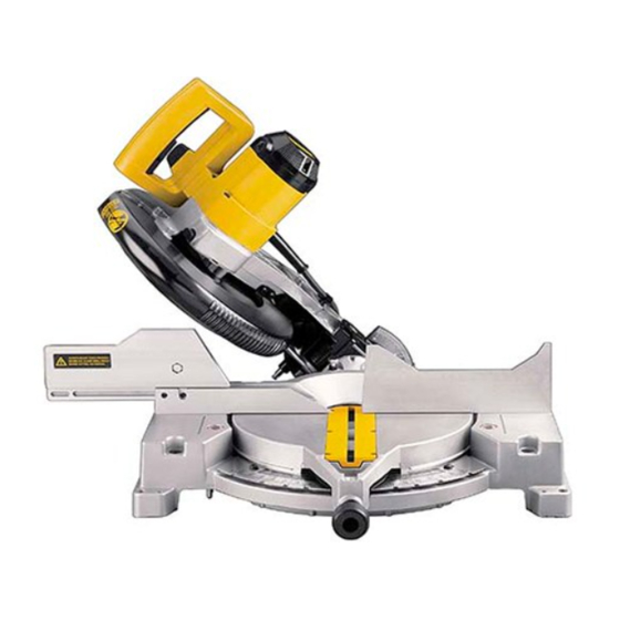
5. One Side Table Extension (Some Models) Familiarization Your miter saw is fully assembled in the carton. Open the box and lift the saw out by the convenient carrying handle, as shown in Figure 1. Place the saw on a smooth, flat surface such as a workbench or strong table. -
Page 8: Accessories
NOTE: If you elect to mount your saw to a piece of plywood, make sure that the mounting screws don’t protrude from the bottom of the wood. The plywood must sit flush on the work support. -
Page 9: Rear Lower Guard Adjustment
In order to conveniently carry the miter saw from place to place, a carrying handle has been included on the top of the saw arm, as shown in Figure 3. To transport the saw, lower the arm and depress the lock down pin shown in Figure 4. -
Page 10: Bevel Stop
FENCE ADJUSTMENT Turn Off and Unplug the Miter Saw In order that the saw can bevel to a full 48 degrees left, the left side of the fence can be adjusted to the left to provide clearance. To adjust the fence, loosen the two plastic knobs shown in Figure 13 and slide the fence to the left. -
Page 11: Automatic Electric Brake
On rare occasions, the brake may not engage at all and the blade will coast to a stop. If a delay or “skipping” occurs, turn the saw on and off 4 or 5 times. If the condition persists, have the tool serviced by an authorized D Walt service center. -
Page 12: Body And Hand Position
Keep both feet firmly on the floor and maintain proper balance. As you move the miter arm left and right, follow it and stand slightly to the side of the saw blade. Sight through the guard louvers when following a pencil line. -
Page 13: Dual Range Miter Scale
(Angle A, Figure 19), use the upper right arc. Find 26° on the arc scale. Follow the horizontal intersecting line to either side to get miter angle setting on saw (42°). Likewise, follow the vertical intersecting line to the top or bottom to get the bevel angle setting on the saw (18°). - Page 14 When mitering to the right side of a base molding wider than 3.9" (3-7/8") standing vertically against the fence as in Figure 22, the saw can only cut through the board up to 1 inch from the end of the board. Trying to cut more than an inch will cause the saw’s gear case to interfere...
-
Page 15: Cutting Base Moldings
CUTTING BASE MOLDING LAYING FLAT AND USING THE BEVEL FEATURE • All cuts made with the saw set at 45° bevel and 0 miter • All cuts made with back of molding laying flat on the as shown in figures 23 and 24... -
Page 16: Cutting Crown Molding
ALTERNATIVE METHOD FOR CUTTING CROWN MOLDING Place the molding on the table at an angle between the fence and the saw table, as shown in Figure 26A. Use of the crown molding fence accessory (DW7054) is highly recommended because of its degree of accuracy and convenience. -
Page 17: Special Cuts
SET THIS BEVEL ANGLE ON SAW This way, when corners other than 90 degrees are encountered, the saw can be quickly and easily adjusted for them. Use the crown molding fence accessory to maintain the angle at which the molding will be on the wall. -
Page 18: Maintenance
Cutting Plastic Pipe or Other Round Material Plastic pipe can be easily cut with your saw. It should be cut just like wood and CLAMPED OR HELD FIRMLY TO THE FENCE TO KEEP IT FROM ROLLING. This is extremely important when making angle cuts. -
Page 19: Trouble Shooting Guide
1. Extension cord too light or too long 2. Low house current TROUBLE! MACHINE VIBRATES EXCESSIVELY WHAT’S WRONG? 1. Saw not mounted securely to stand or work bench 2. Stand or bench on uneven floor 3. Damaged saw blade TROUBLE! DOES NOT MAKE ACCURATE MITER CUTS WHAT’S WRONG? - Page 20 POUR TOUT RENSEIGNEMENT SUPPLÉMENTAIRE SUR CET OUTIL OU TOUT AUTRE OUTIL D WALT, COMPOSER SANS FRAIS LE NUMÉRO: 1 800 4-D WALT (1 800 433-9258) WALT… CONÇU POUR LE CHANTIER Les outils industriels è rendement élevé D WALT répondent aux pires exigences de l’industrie et de la construction en Amérique du Nord.
- Page 21 Table des matières MESURES DE SÉCURITÉ ...18 INSTRUCTIONS RELATIVES À LA DOUBLE ISOLATION ...18 ET AUX FICHES POLARISÉES ...18 CORDONS DE RALLONGE ...18 MESURES DE SÉCURITÉ ADDITIONNELLES ...19 CONNEXION ÉLECTRIQUE...20 DÉBALLAGE ...20 FAMILIARISATION ...20 FICHE TECHNIQUE ...20 ACCESSOIRES FACULTATIFS ...20 ACCESSOIRES ...21 MONTAGE SUR ÉTABLI ...21 INSTALLATION DE LA LAME...22...
-
Page 22: Mesures De Sécurité
IMPORTANTES MESURES DE SÉCURITÉ (POUR TOUS LES OUTILS) AVERTISSEMENT : Afin de réduire les risques d’incendie, de secousses électriques ou de blessures lorsqu’on utilise des outils électriques, il faut toujours respecter les mesures de sécurité suivantes. LIRE TOUTES LES DIRECTIVES. Double isolation Les outils à... -
Page 23: Mesures De Sécurité Additionnelles
• VÉRIFIER LES PIÈCES ENDOMMAGÉES. Avant de continuer à utiliser l’outil, il faut vérifier si le protecteur ou toute autre pièce endommagée remplit bien la fonction pour laquelle il a été prévu. Vérifier l’alignement et les attaches des pièces mobiles, le degré d’usure des pièces et leur montage, ainsi que tout autre facteur susceptible de nuire au bon fonctionnement de l’outil. -
Page 24: Connexion Électrique
PROTECTION. NE PAS EXPOSER À LA PLUIE NI UTILISER DANS DES ENDROITS HUMIDES. SUR LE GUIDE MOBILE: TOUJOURS BIEN RÉGLER LE GUIDE AVANT D’UTILISER LA SCIE. Fixer solidement les ouvrages de petites dimensions avant de procéder à la coupe. Consulter le manuel. SUR LE PROTÈGE-LAME: SE TENIR LOIN DE LA LAME. -
Page 25: Accessoires Facultatifs
être dangereuse. Pour trouver un accessoire, communiquer avec DeWALT ORIFICE Industrial Tool Co., 701 East Joppa Road, Baltimore, MD 21286 É.-U. ou composer le 1 (800) 4-DEWALT N DES (1 (800) 433-9258). Montage sur établi Les quatre pattes de l’outil sont pourvues d’un trou afin d’en faciliter le montage sur établi, comme le montre la... -
Page 26: Installation De La Lame
montage est uniforme afin d’éviter le pliage et l’imprécision. Lorsque la scie oscille sur la surface, placer un morceau de matériau mince sous l’une des pattes de l’outil jusqu’à ce que la scie repose carrément sur la surface de montage. Installation de la lame (Fig. -
Page 27: Transport De La Scie
FIG. 5 VIS DU SUPPORT DU PROTECTEUR FIG. 6 LA DISTANCE ENTRE LA LAME ET PROTECTEUR LE PROTECTEUR INFÉRIEUR DOIT ÊTRE ÉGALE ARRIÉRE DE CHAQUE CÔTÉ RONDELLE DE RONDELLE DE BLOCAGE BLOCAGE INTERNE EXTERNE ADAPTATEUR POUR LAMES VIS DE LA LAME LAME DE SCIE FIG. -
Page 28: Réglage Du Guide
Si cela se produit, ou si la scie saute, démarrer et arrêter celle-ci quatre ou cinq fois. Si le problème persiste, retourner la scie à un centre de service DeWALT autorisé en vue de régler le problème. On doit toujours s’assurer que la lame se soit complètement arrêtée avant de la retirer de la plaque... -
Page 29: Balais
FIG. 13 VIS DE LA BUTÉE GAUCHE POUR BISEAUX BOUTON DE SERRAGE DU GUIDE GAUCHE FIG. 15 TROU POUR CADENAS INTERRUPT EUR À DÉTENTE FIG. 14 RANURE DU GUIDE Balais DÉBRANCHER L’OUTIL. Inspecter régulièrement les balais de carbone en débranchant l’outil, en enlevant le couvercle d’inspection des balais (fig. -
Page 30: Coupes En Biseau
biseaux.) À l’obtention de l’angle de biseau voulu, revisser fermement le bouton de serrage pour biseaux. On peut régler les biseaux à des angles variant entre 3° à droite et 48° à gauche et on peut régler l’indicateur d’onglets entre 0° et 48° à gauche ou à droite. QUALITÉ... -
Page 31: Soutien De Grandes Pieces
FIG. 17 FIG. 18 FIG. 19 ANGLE “A” ÉCHELLE POUR ONGLETS FIG. 20 FIG. 21 PLAQUE RAINURÉE INDICATEUR D´ONGLETS LA MENTION DU CENTRE DE L´ÉCHELLE DU VERNIER S´ALIGNE SUR LE NOMBRE ENTIER VOULU DE L´ÉCHELLE POUR ONGLETS (24˚ À DROITE). LA MENTION 1/4˚... -
Page 32: Onglets Mixtes
FIG. 22 variété de formes. (Dans ce tableau, on suppose que tous les côtés sont de longueur égale.) Pour une forme qui n’est pas illustrée dans le tableau, utiliser la formule suivante. Diviser 180° par le nombre de côtés pour obtenir l’angle de l’onglet ou du biseau. - Page 33 2. Conserver le côté gauche de la coupe. Côté droit 1. Onglet à droite de 45° 2. Conserver le côté droit de la coupe. COIN EXTÉRIEUR Côté gauche 1. Onglet à droite de 45° 2. Conserver le côté gauche de la coupe. Côté...
-
Page 34: Corniches
TABLEAU 1 ONGLETS MIXTES R´EGLAGE DE L´ ANGLE DU BISEAU FIG. 26 GUIDE GUIDE TABLE CORNICHE À PLAT CONTRE LA PLAQUE ET LE GUIDE FIG. 26A DESSOUS DE LA GUIDE POUR MOULURE CORNICHE, MODÉLE DW7054 DESSUS DE LA MOULURE TABLE CORNICHE ENTRE LE GUIDE ET LA PLAQUE arrière (la section qui repose à... -
Page 35: Coupes Particulieres
coupe. Lorsqu’on règle les angles de biseau ou d’onglet pour toutes les coupes en onglets mixtes, il faut se rappeler des points suivants. Les angles des corniches sont très précis et difficiles à régler. Il faut tester les réglages sur des bouts de bois inutiles afin de vérifier les réglages car très peu de pièces ont des coins exactement droits. -
Page 36: Entretien
Guide de dépannage SE CONForMER AUX MESURES DE SÉCURITÉ ET AUX DIRECTIVES. PROBLÈME : LA SCIE NE DÉMARRE PAS. VÉRIFIER SI : 1. La scie est branchée. 2.Le fusible a sauté ou le disjoncteur est enclenché. 3.Le cordon est endommagé. 4.Les balais sont usés. - Page 37 SI TIENE USTED PREGUNTAS O COMENTARIOS SOBRE ESTA HERRAMIENTA, O CUALQUIER OTRA HERRAMIENTA DEWALT, SIRVASE LLAMARNOS SIN CARGO AL NÚMERO: 1-800-4-DEWALT (1-800-433-9258) DEWALT...PARA TRABAJOS PESADOS Las herramientas industriales D WALT de alto rendimiento se han fabricado para las más duras condiciones industriales y de construcción.
- Page 38 Contenido INSTRUCCIONES DE SEGURIDAD...35 DOBLE AISLAMIENTO/CLAVIJA POLARIZADA ...35 INSTRUCCIONES DE SEGURIDAD ADICIONALES ...36 CABLES DE EXTENSION ...36 CONEXION ELECTRICA...37 DESEMPAQUE SU INGLETEADORA ...37 FAMILIARICESE CON SU SIERRA ...37 ESPECIFICACIONES ...37 ACCESORIOS OPCIONALES...37 ACCESORIOS ...39 MONTAJE EN BANCO ...39 INSTALACION DEL DISCO...39 AJUSTE DE LA GUARDA INFERIOR TRASERA ...39 CORTE DE LA PLACA DE RESPALDO ...39 TRANSPORTE DE LA SIERRA...40...
-
Page 39: Instrucciones De Seguridad
Instrucciones importantes de seguridad ADVERTENCIA: Es indispensable sujetarse a las precauciones básicas de seguridad, con la finalidad de reducir el peligro de incendio, choque eléctrico y lesiones personales, en todas las ocasiones en que se utilicen herramientas eléctricas. Entre estas precauciones se incluyen las siguientes. -
Page 40: Instrucciones De Seguridad Adicionales
Calibre mínimo requerido (AWG) para cables de extensión Volts Longitud total del cable de extensión (metros) 120 V 0 - 7.5 7.6 - 15.215. 240 V 0 - 15.2 15.3 - 30.4 30.5 - 60.8 Amperaje en la placa de identificación Más No más Calibre promedio del alambre 10 - 12 12 - 16... -
Page 41: Conexion Electrica
polvo se introduzca en su boca, ojos, o dejarlo sobre la piel promueve la absorción de químicos dañinos. SOBRE LA TAPA DEL MOTOR: ADVERTENCIA: PARA PROPIA SEGURIDAD, MANUAL I N S T R U C C I O N E S ANTES UTILIZAR SIERRA. -
Page 42: Accesorios
GATILLO INTERRUPTOR TAPA DE FIG. 3 INSPECCION ASA DE TRANSPORTE CARBONES BOTON DE SEGURO DE LA FLECHA CARCAZA DEL MOTOR GUARDA INFERIOR TRASERA GUIA LATERAL IZQUIERDA PERILLA DE SEGURO DE INGLETE SEGURO ESCALA INGLETE EXPULSOR ESCALA DE INGLETE DE POLVO BISEL ENTRADA PARA PERILLA DE... -
Page 43: Instalacion Del Disco
PRECAUCION: Para evitar que la sierra se atasque y la falta de precisión, asegúrese que la tabla de montaje no esté desnivelada. Si la sierra se mueve sobre la superficie de trabajo, ponga un trozo de material debajo de una de las patas hasta que la sierra asiente bien sobre la superficie de trabajo. -
Page 44: Transporte De La Sierra
FIG. 5 TORNILLO SOPORTE DE LA GUARDA FIG. 6 GUARDA LA DISTANCIA AL INFERIOR DISCO DEBE SER TRASERA IGUAL ROLDANA DE ROLDANA DE SUJECION SUJECION EXTERIOR EXTERIOR ADAPTADOR DEL DISCO TORNILLO DEL DISCO DISCO DE SIERRA FIG. 7 GUARDA INFERIOR TRASERA FIG. -
Page 45: Ajuste Del Indicador De Inglete
AJUSTE DEL INDICADOR DE LA ESCALA Afloje la perilla de la abrazadera del inglete y apriete el pasador del inglete para mover el brazo de la escala a la posición cero, como se muestra en la figura 9. Con la perilla de la abrazadera del inglete floja, permita que el pasador del inglete se ajuste en su sitio mientras que usted hace girar el brazo de inglete más allá... -
Page 46: Carbones
FIG. 13 TORNILLO DEL TOPE LATERAL IZQUIERDO PERILLA DE FIJACION DE LA GUIA LATERAL IZQUIERDA ORIFICIO PARA CANDADO FIG. 15 FIG. 14 CANAL GUIA INTERUPTOR DE GATILLO prenda y apague la sierra 4 ó 5 veces. Si la situación persiste, lleve la herramienta a un centro de servicio autorizado D WALT para su verificación. -
Page 47: Corte De Bisel
y firmemente contra la guía. Encienda la sierra oprimiendo el interruptor de gatillo como ilustra en la figura 15. Cuando la sierra alcance la velocidad máxima (aproximadamente en un segundo) baje el brazo lentamente para cortar a través de la madera. Deje que el disco se detenga por completo antes de levantar el brazo. -
Page 48: Sujecion De La Pieza De Trabajo
FIG. 17 FIG. 18 FIG. 19 ANGULO “A” ESCALA INGLETE FIG. 20 FIG. 21 PLACA DE RESPALDO BRAZO DE INGLETE LA MARCA CENTRAL DE LA ESCALA VERNIER SE ALINEA CON EL ENTERO DEL ANGULO DESEADO (INGLETE A LA DERECHA DE 24˚) LA MARCA DE 1/4˚... -
Page 49: Corte De Inglete Compuesto
FIG. 22 tipo de unión ponga el ajuste de bisel en cero y el brazo de inglete a 45 grados. De nuevo, ponga la madera con la parte ancha contra la mesa y el extremo recto contra la guía. Los dos dibujos de la figura 17 se aplican únicamente a objetos de cuatro lados. -
Page 50: Corte De Molduras De Remate
2. Conserve la parte derecha del corte ESQUINA EXTERIOR: Lado izquierdo: 1. Inglete derecho a 45° 2. Conserve la parte izquierda del corte LADO DERECHO: 1. Inglete izquierdo a 45° 2. Conserve la parte derecha del corte Se puede cortar material de hasta 98,4 mm (3 7/8””) de espesor como se describe arriba. - Page 51 TABLA 1 CORTE DE INGLETE COMPUESTO OCTAGONAL AJUSTE DE ANGULO DE BISEL AJUSTE ESTE ANGULO DE BISELEN LA SIERRA FIG. 26 GUIA MESA LA MOLDURA PLANA EN LA MESA Y CONTRA LA GUIA CAJA CUADRADA CAJA HEXAGONAL CAJA FIG. 26A LADO INFERIOR GUIA DE LA MOLDURA...
-
Page 52: Cortes Especiales
recomienda el uso de la guía para molduras de remate (DW7054) por su grado de precisión y comodidad. Este accesorio está a su disposición con costo extra con su distribuidor local. La ventaja de cortar las molduras de remate con este método es que no requiere corte a bisel. -
Page 53: Guia Para La Solucion De Problemas Frecuentes
Guía para la solución de problemas frecuentes ASEGURESE DE SEGUIR LAS REGLAS DE SEGURIDAD Y LAS INSTRUCCIONES PROBLEMA: LA SIERRA NO ARRANCA ¿QUE ESTA MAL? 1. La sierra no está conectada. 2. Hay un fusible quemado o el interruptor automático. 3.