
Related Manuals for Nokia IP2255 - Security Appliance


Summary of Contents for Nokia IP2255 - Security Appliance
- Page 1 Nokia IP2255 Security Platform Installation Guide Part No. N450000275 Rev 002 Published March 2007...
- Page 2 Rights clause at FAR 52.227-19. IMPORTANT NOTE TO USERS This software and hardware is provided by Nokia Inc. as is and any express or implied warranties, including, but not limited to, implied warranties of merchantability and fitness for a particular purpose are disclaimed. In no event shall Nokia, or its affiliates, subsidiaries or suppliers be liable for any direct, indirect, incidental, special, exemplary, or consequential damages (including, but not limited to, procurement of substitute goods or services;...
- Page 3 Singapore 119968 Nokia Customer Support Web Site: https://support.nokia.com/ Email: tac.support@nokia.com Americas Europe Voice: 1-888-361-5030 or Voice: +44 (0) 125-286-8900 1-613-271-6721 Fax: 1-613-271-8782 Fax: +44 (0) 125-286-5666 Asia-Pacific Voice: +65-67232999 Fax: +65-67232897 050602 Nokia IP2255 Security Platform Installation Guide...
- Page 4 Nokia IP2255 Security Platform Installation Guide...
-
Page 5: Table Of Contents
Ethernet Management Ports ......23 Nokia Network Interface Cards ......24 Console Port . - Page 6 Viewing Nokia IPSO Documentation by Using Nokia Network Voyager ......54 Using the Command-Line Interface .
- Page 7 Index ..........121 Nokia IP2255 Security Platform Installation Guide...
- Page 8 Nokia IP2255 Security Platform Installation Guide...
- Page 9 Table 3 System Status LEDs ......29 Table 4 Power Supply Status LEDs ..... . 32 Nokia IP2255 Security Platform Installation Guide...
- Page 10 Nokia IP2255 Security Platform Installation Guide...
- Page 11 Figure 10 Power Switch Location (Rear View) ....48 Figure 11 Nokia Network Voyager Reference Access Points . . . 55 Figure 12 Eight-Port Ethernet NIC Front Panel Details ..61 Figure 13 Output Connector for the Ethernet Cable .
- Page 12 Figure 22 Location of Compact-Flash Memory Card ..87 Figure 23 DIMM Socket Locations ..... . . 92 Nokia IP2255 Security Platform Installation Guide...
-
Page 13: About This Guide
About this Guide This manual is written for network administrators. It provides information for the installation and use of the Nokia IP2255 Security Platform. Installation and maintenance should be performed by experienced technicians or Nokia-approved service providers only. This preface provides the following information:... -
Page 14: Conventions This Guide Uses
Chapter 6, “Installing and Replacing Network Interface Cards” describes how to install, monitor, and replace supported network interface cards. Chapter 5, “Installing, Replacing, and Configuring the Nokia Encryption Accelerator Card” describes how to install and replace the Nokia encryption accelerator card and how to configure software to use the Nokia encryption accelerator card. -
Page 15: Text Conventions
Keys that you press simultaneously are linked by a plus sign (+): Press Ctrl + Alt + Del. Menu commands Menu commands are separated by a greater than sign (>): Choose File > Open. Nokia IP2255 Security Platform Installation Guide... -
Page 16: Related Documentation
• Indicates a variable in a command: ls device directory Related Documentation You can find this guide in PDF on the Nokia support Web site (https:// support.nokia.com/) and on the Nokia IPSO operating system CD-ROM issued with your Nokia IP2255 security platform. - Page 17 Related Documentation support.nokia.com). You can access inline help, the Nokia Network Voyager Reference Guide, and the CLI Reference Guide from Nokia Network Voyager. Check Point documentation is available from the Check Point Web site at: http://www.checkpoint.com/ Nokia IP2255 Security Platform Installation Guide...
- Page 18 Nokia IP2255 Security Platform Installation Guide...
-
Page 19: Overview
Overview This chapter provides an overview of the Nokia IP2255 appliance and the requirements for its use. The following topics are covered: About the Nokia IP2255 Security Platform Managing the Nokia IP2255 Appliance Nokia IP2255 Appliance Overview Product Disposal Site Requirements, Warnings, and Cautions... -
Page 20: Managing The Nokia Ip2255 Appliance
Managing the Nokia IP2255 Appliance You can manage the Nokia IP2255 appliance by using one of the following interfaces: Nokia Network Voyager—an SSL-secured, Web-based element management interface to Nokia IP Security Platforms. Network Voyager is preinstalled on the IP2255 appliance and enabled through the IPSO operating system. -
Page 21: Nokia Ip2255 Appliance Overview
Nokia proprietary IPSO operating system, plus hardware and third-party applications such as Check Point VPN-1. Horizon Manager can perform installations and upgrades on up to 2,500 Nokia IP Security Platforms, offering administrators the most rapid and dependable method to perform Check Point application upgrades. -
Page 22: Figure 1 Component Locations Front View
PC-card slots management ports The flash memory in the internal compact-flash slot provides the primary application and operating system storage. The power supplies are located at the back of the IP2255 appliance, as shown Figure Nokia IP2255 Security Platform Installation Guide... -
Page 23: Ethernet Management Ports
The Nokia IP2255 appliance management ports are not suitable for forwarding production data traffic. Do not use them for this purpose. Nokia recommends that you configure one port as the primary management interface and a second port as the backup management interface. -
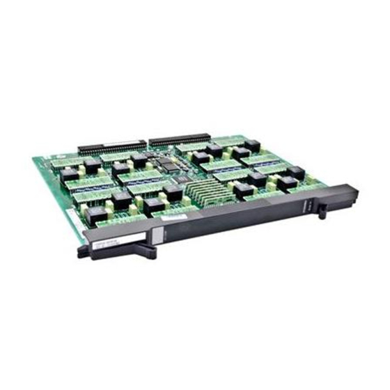
Page 24: Nokia Network Interface Cards
Electromagnetic Interference and Immunity performance. Nokia Network Interface Cards The Nokia IP2255 appliances have four network interface card (NIC) slots. Each slot can accommodate one NIC. The NICs interface with the ADP subsystem. Figure 4 shows the slot numbers for the NIC slots. -
Page 25: Table 2 Nics Available For The Network Interface Card Slots
Slot 4 Slot 5 contains the cPCI Ethernet management ports and does not connect to the ADP subsystem. Nokia IP2255 appliances support the ADP format network interface cards listed in Table Table 2 NICs Available for the Network Interface Card Slots ADP format NIC For details, see... -
Page 26: Console Port
Overview Note Nokia products support network interface cards purchased from Nokia or Nokia-approved resellers only. The Nokia Global Support Services group can provide support only for Nokia products that use Nokia-approved accessories. For sales or reseller information, contact a Nokia service provider listed in the “Nokia Contact Information”... -
Page 27: Serial Port
Output Serial Port Use the built-in serial (AUX) port, shown in Figure 1 on page 22 to establish a modem connection to manage the appliance. Figure 6 provides pin- assignment information for modem connections. Nokia IP2255 Security Platform Installation Guide... -
Page 28: Figure 6 Pin Assignments For Modem Connection
5 (GND) 7 (GND) 5 (GND) 6 (DSR) Input 6 (DSR) 4 (DTR) 7 (RTS) Output 4 (RTS) 1 (DCD) 8 (CTS) Input 5 (CTS) 1 (DCD) 9 (RI) Output 22 (RI) 4 (DTR) Nokia IP2255 Security Platform Installation Guide... -
Page 29: System Status Leds
00025 Table 3 shows the system status LEDs and describes their meaning. Table 3 System Status LEDs Status indicator Meaning Symbol Solid blue Power on Solid yellow Appliance is experiencing an internal voltage problem. Nokia IP2255 Security Platform Installation Guide... -
Page 30: Fan Unit
Chapter 4, “Connecting to the Network Interface Cards.” Fan Unit The Nokia IP2255 appliance fan unit is a single unit made up of four individual fans to provide the air flow required to maintain a proper operating temperature. The fan unit provides N + 1 cooling, so it can provide proper airflow even if an individual fan fails. -
Page 31: Storage Devices
Nokia IP2255 Appliance Overview Storage Devices Nokia IP2255 appliances do not include any hard-disk drives. Application and operating system storage is provided with flash memory in the compact flash and PC-card slots. You can use a flash-memory PC card in the IP2255... -
Page 32: Product Disposal
These devices contain materials and components that must be disposed of properly. Therefore, to help prevent damage to the environment, Nokia encourages you to dispose of these devices in an environmentally-friendly manner. -
Page 33: Site Requirements, Warnings, And Cautions
The following resources are available to you to help with equipment-disposal decisions: Many Nokia products are labeled with information about the materials used in their manufacture that can help those who will process equipment after you have disposed of it. -
Page 34: Software Requirements
Do not block any ventilation slots on the appliance. Internal components might overheat and be damaged. Software Requirements The Nokia IP2255 appliance requires the use of the following operating system and firewall software versions: Operating system requirements—Nokia IPSO v4.1 or later Firewall and VPN software requirements—Check Point VPN-1... - Page 35 Software Requirements For information about updates to the software requirements or additional applications that have become available since this guide was published, contact your Nokia service provider, as listed in “Nokia Contact Information” on page 3. Nokia IP2255 Security Platform Installation Guide...
- Page 36 Overview Nokia IP2255 Security Platform Installation Guide...
-
Page 37: Installing Nokia Ip2255 Appliances
Installing Nokia IP2255 Appliances This chapter describes how to install Nokia IP2255 appliances in a standard equipment rack. Caution To help guard against electrostatic discharge damage, make sure you are properly grounded by using a grounding wrist strap and following the instructions provided with the wrist strap before you handle the components or open the appliance. -
Page 38: Before You Begin
Before You Begin Since the Nokia IP2255 appliances are very heavy, Nokia recommends that you remove the power supplies, fan unit, and chassis tray assembly from the chassis before you install the security platform in the equipment rack. - Page 39 10Base-SR X2 10/100 BaseT SLOT 2 SLOT 4 SLOT 5 10/100/1000BaseT CONSOLE PCMCIA RESET 00010 Fan unit Retaining screws b. Loosen the retaining screws by turning them counterclockwise by hand or by using a screwdriver. Nokia IP2255 Security Platform Installation Guide...
- Page 40 Locate the power supplies on the back of the appliance and the two retaining screws that secure each power supply. Retaining screws (4) FAULT FAULT TEMP TEMP 00034 b. Loosen the retaining screws by turning them counterclockwise. Nokia IP2255 Security Platform Installation Guide...
- Page 41 Rack Mounting the Security Platform c. Use the handle to gently pull each power supply out of the chassis. 00083 4. Optionally, remove the chassis tray assembly from the security platform. Nokia IP2255 Security Platform Installation Guide...
- Page 42 Loosen the four chassis tray assembly retaining screws from the front panel of the appliance. IP2255 SLOT 1 SLOT 3 10Base-SR X2 10/100 BaseT 10Base-SR X2 10/100 BaseT SLOT 2 SLOT 4 SLOT 5 10/100/1000BaseT CONSOLE PCMCIA RESET 00010 Chassis tray assembly retaining screws Nokia IP2255 Security Platform Installation Guide...
- Page 43 Chassis tray assembly release tab 00094 You must lift the right side of the chassis tray assembly slightly as you pull it out of the chassis so that the release tab clears the slot on the chassis. Nokia IP2255 Security Platform Installation Guide...
- Page 44 7. Slide the chassis tray assembly back into the appliance until it clicks into place and resecure the four chassis tray assembly retaining screws. 8. Reinstall the fan unit into the front of the appliance. 9. Reinstall the power supplies. Nokia IP2255 Security Platform Installation Guide...
-
Page 45: Performing The Initial Configuration
Performing the Initial Configuration The first time you turn on power to a Nokia IP2255 appliance, the initial configuration process begins. This process enables you to configure the network settings and provides access to the admin account. You can perform the initial configuration in two ways: Configure a DHCP server to provide the initial configuration information the first time the appliance is started. -
Page 46: Using A Console Connection
Nokia Encryption Accelerator Card.” Using a Console Connection If you do not use DHCP to perform the initial configuration of your Nokia appliance, you must use a serial console connection (cable included). After you perform the initial configuration, you no longer need the console connection. -
Page 47: Connecting Power And Turning The Power On
Connecting Power and Turning the Power On A power switch and a receptacle for the power cord are located on each power supply on the back of the appliance as shown in Figure Nokia IP2255 Security Platform Installation Guide... -
Page 48: Figure 10 Power Switch Location (Rear View)
Caution To avoid potential service interruptions from momentary facility power interruptions and potential power spikes that might damage your equipment, Nokia strongly recommends that you use an uninterruptible power supply (UPS) with surge protection with your appliance. To connect the power supply 1. - Page 49 5. Check the power LED (the Nokia logo) on the front panel of the appliance to ensure that the power supply is operating correctly. For more information about the system status LEDs, see “System Status...
-
Page 50: Performing The Initial Configuration
Type any character to enter command mode. The prompt remains on the screen for about five seconds. Note For information about how to use the boot manager, see the Nokia IPSO Boot Manager Reference Guide . After some miscellaneous output appears, the following prompt appears:... - Page 51 Performing the Initial Configuration prompts, verify that the terminal or terminal emulator program settings are correct. If the settings are correct, contact your Nokia service provider as listed in “Nokia Contact Information” on page 3. 2. Respond to the Hostname? prompt within 30 seconds to prevent the DHCP client from starting.
-
Page 52: Connecting Network Interfaces
Network Voyager to configure them. Connecting Network Interfaces Connect the interface that you configured during the initial configuration to the network to use as the Nokia Network Voyager system-management interface. You can also connect the remaining LAN interface cables at this point, although you are not required to do so. -
Page 53: Using Nokia Network Voyager
“10/100 Ethernet NIC Connectors and Cables” page 61. Using Nokia Network Voyager Use Nokia Network Voyager to configure and monitor your appliance. For additional information about how to use Network Voyager, see “Viewing Nokia IPSO Documentation by Using Nokia Network Voyager”... -
Page 54: Viewing Nokia Ipso Documentation By Using Nokia Network Voyager
Viewing Nokia IPSO Documentation by Using Nokia Network Voyager The following documentation is available in Nokia Network Voyager and is accessible from the Network Voyager interface, as shown in Figure Nokia Network Voyager Reference Guide—This guide is the comprehensive reference source for Nokia Network Voyager. -
Page 55: Using The Command-Line Interface
Using the Command-Line Interface You can also use the IPSO command-line interface (CLI) to manage and configure Nokia appliances from the command line. Everything that you can accomplish with Network Voyager you can also do with the CLI. Nokia IP2255 Security Platform Installation Guide... - Page 56 The argument must be the filename name of a regular file. For more information about how to access and use the CLI, see the Nokia CLI Reference Guide for the version of IPSO you are using. Nokia IP2255 Security Platform Installation Guide...
-
Page 57: Using Nokia Horizon Manager
Using Nokia Horizon Manager Using Nokia Horizon Manager Nokia Horizon Manager is an extension of the Network Voyager management functionality. While Network Voyager provides the device administrator access to network configuration tasks (such as interface configuration and routing configuration) and security configuration tasks (such as user configuration and access configuration), Horizon Manager concentrates on secure software image, inventory, and platform management of Nokia IP security platforms. - Page 58 Performing the Initial Configuration Nokia IP2255 Security Platform Installation Guide...
-
Page 59: Connecting To The Network Interface Cards
Connecting to the Network Interface Cards This chapter describes the network interface cards (NICs) available for the Nokia IP2255 appliance and how to connect those NICs to your network. The following NICs are described: Eight-Port 10/100 Ethernet NIC Two-Port and Four-Port Copper Gigabit Ethernet NIC... -
Page 60: Eight-Port 10/100 Ethernet Nic
Eight-Port 10/100 Ethernet NIC Every Nokia IP2255 appliance has four dual-mode 10-Mbps and 100-Mbps Ethernet ports for management and synchronization traffic. Additionally, the Nokia IP2255 appliances support Nokia-approved, eight-port UTP5 dual-mode 10-Mbps and 100-Mbps Ethernet NICs. -
Page 61: 10/100 Ethernet Nic Connectors And Cables
Use a straight-through cable to connect the NIC to a 10-Mbps or 100-Mbps hub or switch. Use a crossover cable to connect directly to a host. Use IEEE 802.3 10BASE-T, 100Base-TX Cat 5 shielded twisted-pair, full-duplex, or half-duplex cable. Nokia IP2255 Security Platform Installation Guide... -
Page 62: Figure 13 Output Connector For The Ethernet Cable
Connecting to the Network Interface Cards Note For IP2255 appliances, Nokia recommends the use of shielded twisted- pair cables and connectors for best Electromagnetic Interference and Immunity performance. Figure 13 shows the pin assignments for the straight-through cable with an RJ-45 connector. -
Page 63: Figure 14 Ethernet Crossover-Cable Pin Connections
You can also use cables intended for Gigabit Ethernet NIC connections for your Ethernet NIC connections, as shown in Figure Figure 15 Gigabit Ethernet Crossover Cable Pin Connections 00020 You can order appropriate adapter cables separately from a cable vendor of your choice. Nokia IP2255 Security Platform Installation Guide... -
Page 64: Two-Port And Four-Port Copper Gigabit Ethernet Nic
Connecting to the Network Interface Cards Two-Port and Four-Port Copper Gigabit Ethernet The Nokia IP2255 appliance supports Nokia-approved, two-port and four-port copper Gigabit Ethernet NICs. For software requirements applicable to this product, see “Software Requirements” on page 34. Copper Gigabit Ethernet NIC Features The copper Gigabit Ethernet NIC supports tracing through tcpdump. -
Page 65: Copper Gigabit Ethernet Nic Connectors And Cables
RJ-45 connectors. Use a straight-through or crossover cable to connect the NIC to a 1000-Mbps hub or switch or to connect directly to a host. Use IEEE 802.3 1000BASE-TX Cat 5, shielded twisted-pair, full-duplex, or half-duplex cable. Nokia IP2255 Security Platform Installation Guide... -
Page 66: Figure 18 Gigabit Ethernet Crossover-Cable Pin Connections
Connecting to the Network Interface Cards Note For IP2255 appliances, Nokia recommends the use of shielded twisted- pair cables and connectors for best Electromagnetic Interference and Immunity performance. For straight-through cable pin assignments, see Figure 13 on page 62 and for... -
Page 67: Two-Port And Four-Port Fiber-Optic Gigabit Ethernet Nic
Two-Port and Four-Port Fiber-Optic Gigabit Ethernet NIC Two-Port and Four-Port Fiber-Optic Gigabit Ethernet NIC The Nokia IP2255 appliance supports Nokia-approved, two-port and four-port multimode fiber-optic Gigabit Ethernet NICs. For software requirements applicable to this product, see “Software Requirements” on page 34. -
Page 68: Fiber-Optic Gigabit Ethernet Nic Connectors And Cables
Ethernet device. You can also use a half-duplex LC-to-LC cable to loop back the transmit port of an interface to the receive port. Two LC-to-SC cables are included with each two-port Gigabit Ethernet NIC. Nokia IP2255 Security Platform Installation Guide... -
Page 69: Single-Port Fiber-Optic 10 Gigabit Ethernet Nic
Support for VLAN, as specified by the IEEE 802.1q standard Figure 21 shows the front panel details for the single-port fiber-optic 10 Gigabit Ethernet NIC you can use in Nokia IP2255 appliances. Note The NIC shown in the figure is the short range version; the LEDs are the same for both short-range and long-range versions. -
Page 70: Fiber-Optic 10 Gigabit Ethernet Nic Connectors And Cables
LC and SC define the fiber-optic connector types; LC connectors are smaller than SC connectors. An LC-to-SC cable is included with single-port fiber-optic 10 Gigabit Ethernet NICs. You can order additional 10GBASE-SR (for short-range Nokia IP2255 Security Platform Installation Guide... - Page 71 10GBASE-LR (for long-range interfaces) compatible cables from a cable vendor of your choice. Cables that connect to the 10 Gigabit Ethernet NIC must be IEEE 802.3 compliant to prevent potential data loss. Nokia IP2255 Security Platform Installation Guide...
- Page 72 Connecting to the Network Interface Cards Nokia IP2255 Security Platform Installation Guide...
-
Page 73: Installing, Replacing, And Configuring The Nokia Encryption Accelerator Card
The Nokia encryption accelerator card has no external ports or LEDs and requires no cables. When you specify that a Nokia encryption accelerator card is to be included with a Nokia appliance, the card is installed before the appliance is delivered to you. -
Page 74: Before You Begin
Removing, Installing, and Replacing the Nokia Encryption Accelerator Card The Nokia IP2255 appliances have four slots on the front of the appliance that hold one NIC each. You can install the Nokia encryption accelerator card in any available slot. - Page 75 Removing, Installing, and Replacing the Nokia Encryption Accelerator Card To remove, install, or replace the Nokia encryption accelerator card 1. Use Network Voyager or the CLI halt command to perform an orderly shutdown of the appliance. Note You do not need to turn off power to the security platform.
- Page 76 Installing, Replacing, and Configuring the Nokia Encryption Accelerator Card 5. Press or push the lever toward the outer edge of the appliance. Ejector and locking lever Push red button to disengage Unscrew or engage screw lock to release Release -S R...
- Page 77 0 /1 a se 00305 8. Insert the new or replacement Nokia encryption accelerator card into the empty slot on the front of the appliance until it clicks into place. Note If you remove a NIC and do not install a new one, make sure you install a cover plate onto the front of the empty slot formerly occupied by the NIC you removed.
-
Page 78: Configuring And Activating Encryption Acceleration
Nokia encryption accelerator card. For the Nokia IP2255 appliances, SecureXL is on by default. After you install the Nokia encryption accelerator card and reboot the appliance, SecureXL automatically uses the Nokia encryption accelerator card for encryption acceleration. -
Page 79: Installing And Replacing Network Interface Cards
Installing and Replacing Network Interface Cards The Nokia IP2255 appliance supports network interface cards (NICs) in the Nokia accelerated data path (ADP) format. The Nokia IP2255 appliances come with the NICs you ordered already installed. You can hot swap the NICs in any of the four slots on the front of the chassis. -
Page 80: Removing, Installing, And Replacing Nics
Removing, Installing, and Replacing NICs The Nokia IP2255 appliances have four slots on the front of the appliance that hold one NIC each. Because the Nokia IP2255 appliances support hot swapping of NICs, you do not have to turn off power from the system to remove, install, or replace a NIC. -
Page 81: Before You Begin
If no NIC is currently installed, remove the two retaining screws on the blank plate that covers the slot and proceed to step 3. Press the red button on the ejector and locking lever on the NIC. The lock is released. Nokia IP2255 Security Platform Installation Guide... - Page 82 /1 0 0 /1 a se 00062 5. Continue to press or push the lever outward until the NIC is released and extends slightly beyond the front panel of the appliance. Nokia IP2255 Security Platform Installation Guide...
- Page 83 If you remove a NIC and do not install a new one, you must install a cover plate onto the front of the empty slot formerly occupied by the NIC you removed. The cover plate is required for the Nokia IP2255 appliances to meet emissions requirements during operation.
-
Page 84: Configuring And Activating Interfaces
The Nokia IP2255 appliance automatically detects any new NICs when they are completely installed. If you are replacing a NIC with a new NIC of the same type, the Nokia IPSO operating system automatically recognizes the NIC and applies the original configuration to the new NIC. -
Page 85: Installing And Replacing Other Components
For information about how to add or replace network interface cards (NICs), Chapter 6, “Installing and Replacing Network Interface Cards.” information about how to add or replace the Nokia encryption accelerator card, see “Installing, Replacing, and Configuring the Nokia Encryption Accelerator Card”... -
Page 86: Replacing The Compact-Flash Memory Card
The compact-flash memory card is located in a slot on the motherboard near the front of the chassis. You cannot see the compact-flash memory card unless you remove the fan tray. Figure 22 shows the location of the compact-flash memory card. Nokia IP2255 Security Platform Installation Guide... - Page 87 00180 To replace the compact-flash memory card, you need: Physical access to the appliance Access to the appliance by using Nokia Network Voyager or the CLI A Phillips-head screwdriver Replacement compact-flash memory card and accompanying documentation You must perform an orderly shutdown of the appliance and turn the power off whenever you open the chassis tray assembly to service internal components.
- Page 88 Note Make sure you turn off both power supplies. 3. Locate the fan unit and the two retaining screws that secure it to the chassis on the front of the appliance. Nokia IP2255 Security Platform Installation Guide...
- Page 89 6. Loosen the four chassis tray assembly retaining screws on the front panel of the appliance. IP2255 SLOT 1 SLOT 3 10/100 BaseT 10Base-SR X2 10Base-SR X2 10/100 BaseT SLOT 4 SLOT 2 SLOT 5 10/100/1000BaseT CONSOLE PCMCIA RESET 00010 Chassis tray assembly retaining screws Nokia IP2255 Security Platform Installation Guide...
- Page 90 10. Slide the chassis tray assembly back into the appliance until it clicks into place. 11. Resecure the four chassis tray assembly retaining screws. 12. Replace the fan unit and resecure the two fan unit retaining screws. Nokia IP2255 Security Platform Installation Guide...
-
Page 91: Replacing The Memory
2 GB of memory in four 512-MB DIMMs, which is the maximum supported memory configuration. Note Nokia products only support memory kits purchased from Nokia or Nokia- approved resellers. For further information, contact the appropriate Nokia customer support site listed in “Nokia Contact Information”... - Page 92 To replace the appliance memory, you need: Physical access to the appliance Access to the security platform by using Nokia Network Voyager or the A Phillips-head screwdriver Nokia IP2255 Security Platform Installation Guide...
- Page 93 Replacing the Memory Nokia memory kit and accompanying documentation You must install DIMMs in pairs starting from the slot closest to the back of the chassis. To replace DIMMs 1. Use Network Voyager or the CLI halt command to perform an orderly shutdown of the appliance.
- Page 94 Chassis tray assembly release tab 00094 You must lift the right side of the chassis tray assembly slightly as you pull it out of the chassis so that the release tab clears the slot on the chassis. Nokia IP2255 Security Platform Installation Guide...
- Page 95 Be sure the contacts and slots are properly aligned before you insert the DIMM. 00299 The retaining clips move into the lock position as you press the DIMM into place. Nokia IP2255 Security Platform Installation Guide...
-
Page 96: Replacing The Fan Unit
Make sure you turn on both power supplies. Replacing the Fan Unit The Nokia IP2255 appliance fan tray assembly is a single-unit made up of four individual fans to provide the air flow required to maintain a proper operating temperature. The fan unit provides N + 1 cooling, so it can provide proper airflow even if an individual fan fails. - Page 97 3. Slowly pull the fan unit out of the chassis toward the front. - S R - S R Retaining screws 00081 4. If the appliance is running, immediately install a replacement fan unit by sliding it into the security platform. Nokia IP2255 Security Platform Installation Guide...
-
Page 98: Replacing A Power Supply
5. Resecure the two retaining screws on the new fan unit. Replacing a Power Supply The power supplies are located at the rear of the Nokia IP2255 appliance. To hot swap a power supply, make sure you turn off and replace only one power supply at a time. - Page 99 7. Resecure the two retaining screws. 8. Connect the power cord to the power supply. Nokia recommends that you connect the power cord to the power supply only when it is safely installed in the chassis. 9. Turn on power to the power supply.
-
Page 100: Replacing The Management Nic
Note Make sure you turn off both power supplies. 3. Disconnect the Ethernet cables from the ports on the management NIC. Nokia IP2255 Security Platform Installation Guide... - Page 101 Continue to press or push the lever outward until the NIC is released and extends slightly beyond the front panel of the appliance. e. Gently pull the NIC out from the slot and place it on a suitable, grounded work surface. Nokia IP2255 Security Platform Installation Guide...
- Page 102 3. Install the two screws into the front panel of the NIC. 4. Reinsert the NICs or blank plates that you removed from slot 3 and slot 4. 5. Resecure the retaining screws on the front of each NIC. Nokia IP2255 Security Platform Installation Guide...
- Page 103 If you still cannot access Network Voyager, or if the status LEDs do not indicate a connection, see the “Nokia Contact Information” on page 3 for information about how to contact your Nokia service provider. Nokia IP2255 Security Platform Installation Guide...
- Page 104 Installing and Replacing Other Components Nokia IP2255 Security Platform Installation Guide...
-
Page 105: Troubleshooting
Troubleshooting This chapter provides troubleshooting tips, problems, and solutions related to IP2255 appliance installations. For information about how to reinstall the operating system (Nokia IPSO) on your appliance, see the Nokia IPSO Boot Manager Reference Guide. General Troubleshooting Information The information in this section relates to problems you might encounter during the IP2255 appliance installation. - Page 106 10 Gigabit Ethernet interfaces. Solution The MTU size must be 1500 (for Ethernet interfaces) or 1518 (for four-port Gigabit Ethernet interfaces) or 9600 (for.two-port Gigabit Ethernet interfaces or 10 Gigabit Ethernet interfaces). Nokia does not support larger MTU sizes. Appliance Not Receiving Power Problem Power cord is not properly plugged in.
- Page 107 Solution Verify terminal settings: 8 data bits, 1 stop bit, no parity, 9600 bps. Problem Terminal set for flow control. Solution The Nokia IP2255 appliances do not use flow control. The terminal should be set for no flow control. Problem Defective appliance or file system.
- Page 108 For information about how to access Network Voyager and the related reference materials, see “Using Nokia Network Voyager” on page 53. 2. Under Configuration Database Management (Config > System Configuration > Manage Configuration Sets), choose the option to create a new factory default configuration. Nokia IP2255 Security Platform Installation Guide...
- Page 109 For information about how to complete the full installation procedure, see the current release notes. The release notes are located on the Nokia customer support Web site as listed in the “Nokia Contact Information”...
- Page 110 NIC. Do Not See Interfaces that Should be Present Problem Local appliance ports do not appear. Solution Your NIC might be defective. Contact the appropriate Nokia customer support site as listed in “Nokia Contact Information”...
- Page 111 Appliance Does Not Recognize New Memory Configuration Problem The DIMMs are not properly seated in DIMM sockets. Solution Repeat memory installation procedures. Make sure DIMMs are fully seated in sockets. Be sure DIMMs click into place. Nokia IP2255 Security Platform Installation Guide...
- Page 112 Troubleshooting Nokia IP2255 Security Platform Installation Guide...
-
Page 113: A Technical Specifications
96 consecutive hours) Space Requirements The IP2255 appliances are designed for front-screw mounting in a 19-inch rack. Each appliance requires the following space in a rack: 5.25 inches (13.5 centimeters) of vertical space Nokia IP2255 Security Platform Installation Guide... - Page 114 7 inches (18 centimeters) behind the appliance to allow the back exit fan to move air through the appliances and to remove the power supply Caution Do not block the ventilation holes on the appliance. The appliance might overheat and become damaged. Nokia IP2255 Security Platform Installation Guide...
-
Page 115: B Compliance Information
This appendix contains the following compliance information: Declaration of Conformity Compliance Statements FCC Notice (US) Declaration of Conformity According to ISO/IEC Guide 22 and EN 45014: Manufacturer’s Name: Nokia Inc. Manufacturer’s Address: 313 Fairchild Drive Mountain View, CA 94043-2215 Nokia IP2255 Security Platform Installation Guide... - Page 116 A11:1998 with Japanese National Deviations EMC: EN55024 1998, EN55022A 1998, EN61000-3-2, EN61000-3-3 Supplementary information: Pursuant to directive 1999/5/EC this product complies with the requirements of the Low Voltage Directive 73/23/EEC and the EMC Directive 89/336/EEC with Amendment 93/68/EEC. Nokia IP2255 Security Platform Installation Guide...
-
Page 117: Compliance Statements
Security & Mobile Connectivity, Enterprise Solutions Mountain View, CA Compliance Statements This hardware complies with the standards listed in this section. Emissions Standards FCC Part 15 Subpart B Class A US/Canada EN55022 (CISPR 22 Class A) European Community (CE) Nokia IP2255 Security Platform Installation Guide... -
Page 118: Fcc Notice (Us)
Part 15 of the FCC Rules. These limits are designed to provide reasonable protection against harmful interference in a residential installation. This device generates, uses, and can radiate radio frequency Nokia IP2255 Security Platform Installation Guide... - Page 119 Consult the dealer or an experienced radio/TV technician for help. Caution Any changes or modifications not expressly approved by the grantee of this device could void the user’s authority to operate the equipment. 060425 Nokia IP2255 Security Platform Installation Guide...
- Page 120 Compliance Information Nokia IP2255 Security Platform Installation Guide...
-
Page 121: Index
47 compact flash 22, 31 database settings, resetting card location declaration of conformity replacing DHCP client startup 51 compliance statements DHCP server, initial configuration 45 component locations 21 Nokia IP2255 Security Platform Installation Guide Index - 121... - Page 122 52, 53 Horizon Manager, Nokia 21 hostname, assigning 50 hot swap network interface cards , 80 network interface cards power supplies 31 eight-port Ethernet list of available 59 monitoring Index - 122 Nokia IP2255 Security Platform Installation Guide...
- Page 123 33 physical names, management ports 24 slot numbering , 52 pin assignments space requirements 113 console connection 27 specifications, technical 113 modem connection 28 storage devices PKCS#11 token synchronization traffic 23 Nokia IP2255 Security Platform Installation Guide Index - 123...
- Page 124 46 text conventions 15 troubleshooting, general information two-port copper Gigabit Ethernet network interface card two-port Ethernet network interface card 70 two-port fiber-optic Gigabit Ethernet network interface card warning notices 14 Index - 124 Nokia IP2255 Security Platform Installation Guide...