Advertisement
Table of Contents
- 1 Safety Guidelines - Definitions
- 2 General Safety Rules
- 3 Power Connections
- 4 Motor Specifications
- 5 Grounding Instructions
- 6 Extension Cords
- 7 Functional Description
- 8 Unpacking and Cleaning
- 9 Operating Controls and Adjustments
- 10 Spindle Speeds
- 11 Drilling Holes to Depth
- 12 Installing and Removing Drill Bits
- 13 Correct Drilling Speeds
- 14 Maintenance
- 15 Drilling Metal
- 16 Parts, Service or Warranty Assistance
- Download this manual
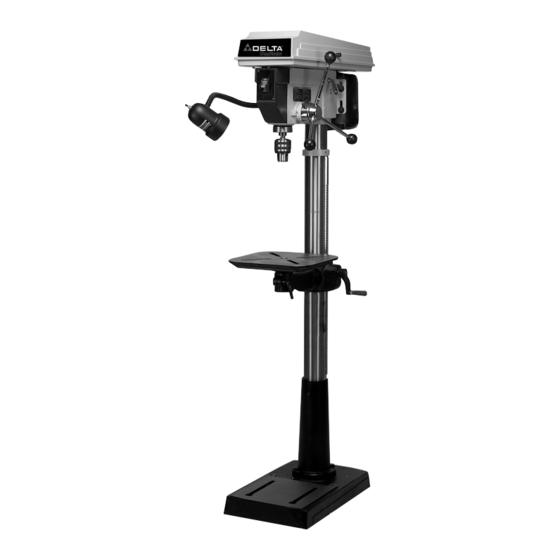
16½" Floor Model Drill Press
(Model DP400)
PART NO. 907453 - 04-13-04
Copyright © 2004 Delta Machinery
To learn more about DELTA MACHINERY
ESPAÑOL: PÁGINA 21
visit our website at: www.deltamachinery.com.
For Parts, Service, Warranty or other Assistance,
1-800-223-7278 (
1-800-463-3582).
please call
In Canada call
Advertisement
Table of Contents

Related Manuals for Delta ShopMaster DP400


Summary of Contents for Delta ShopMaster DP400
- Page 1 16½" Floor Model Drill Press (Model DP400) PART NO. 907453 - 04-13-04 Copyright © 2004 Delta Machinery To learn more about DELTA MACHINERY ESPAÑOL: PÁGINA 21 visit our website at: www.deltamachinery.com. For Parts, Service, Warranty or other Assistance, 1-800-223-7278 ( 1-800-463-3582).
-
Page 2: Safety Guidelines - Definitions
If you have any questions relative to a particular application, DO NOT use the machine until you have first contacted Delta to determine if it can or should be performed on the product. - Page 3 13. USE RECOMMENDED ACCESSORIES. The use of accessories and attachments not recommended by Delta may cause damage to the machine or injury to the user. 14. USE THE PROPER EXTENSION CORD. Make sure your extension cord is in good condition. When using an extension cord, be sure to use one heavy enough to carry the current your product will draw.
- Page 4 DRILL BIT, CUTTING TOOL, OR SANDING DRUM TO STOP TURNING prior to cleaning the work area, removing debris, removing or securing work-piece, or changing the angle of the table. A moving drill bit, cutting tool, or sanding drum can cause serious injury.
-
Page 5: Power Connections
A separate electrical circuit should be used for your machines. This circuit should not be less than #12 wire and should be protected with a 20 Amp time lag fuse. If an extension cord is used, use only 3-wire extension cords which have 3- prong grounding type plugs and matching receptacle which will accept the machine’s plug. -
Page 6: Extension Cords
FOREWORD Delta ShopMaster DP400 is a 16½" drill press with a 120/240 V, 3/4 H.P. induction motor, a flexible work lamp and a tilting table with c-clamp edges and diagonal slots. The Delta ShopMaster Model DP400 has a 5/8” capacity chuck and a 3 3/8”... -
Page 7: Unpacking And Cleaning
14. Table Lock Lever 15. Chuck Key 16. M8x1.25x125mm carriage head screw, flat washer, lockwasher, and hex nut (2 ea.) (for fastening drill press to a supporting surface) 17. M10x1.5x40mm Hex Head Screws (4) 18. M6x1x12mm Hex Cap Head Screw (2) 19. - Page 8 MACHINE IS COMPLETELY ASSEMBLED AND YOU READ AND UNDERSTAND THE ENTIRE INSTRUCTION MANUAL. 1. If your drill press is to be used in a permanent location, the drill press base must be secured to the supporting surface with fasteners through the two mounting holes, (A) Fig.
- Page 9 6. Assemble the column (A) Fig. 6, to the base (B) using the four M10x40mm hex head screws (C), three of which are shown. 7. Assemble table raising and lowering handle (D) Fig. 7, to worm gear shaft (E) and tighten screw (F) against flat on shaft with 3mm wrench supplied.
- Page 10 10. Thread table locking lever (J) Fig. 10, into hole in front of table bracket as shown. 11. Place the drill press head (K) Fig. 11, onto the column as far as it will go. Align head (K) Fig. 12, with table (L) Fig.
- Page 11 14. IMPORTANT: Make certain the spindle taper (O) Fig. 14, and tapered hole in chuck (P) are clean and free of any grease, lacquer or rust preventive coatings. NOTE: Household oven cleaner can effectively remove any sub- stance from the chuck; however, carefully follow the manufacturer's safety rules concerning its use.
- Page 12 18. Align the two holes in the lamp bracket (A) Fig. 17, with the two holes (B) on the side of the drill press head. 19. Place the cord bushing (C) Fig. 17, around the top of the lamp cord (D).
-
Page 13: Operating Controls And Adjustments
STARTING AND STOPPING DRILL PRESS The switch (A) Fig. 20, is located on the front of the drill press head. To turn the drill press “ON” move the switch up to the “ON” position. To turn the drill press “OFF”... - Page 14 3. The table can be tilted right or left by pulling out and removing table alignment pin (C) Fig. 24. NOTE: If pin (C) is difficult to remove, turn nut (E) clockwise to pull pin out of casting. 4. Fig. 25, illustrates the table alignment pin (C) removed.
-
Page 15: Spindle Speeds
SPINDLE SPEEDS Twelve spindle speeds are available on the drill press. Fig. 27, illustrates which steps of the pulleys the belts must be placed to obtain the twelve speeds available. CHANGING SPEEDS AND ADJUSTING BELT TENSION NOTE: A BELT POSITIONING SPEED CHART (E) FIG. -
Page 16: Drilling Holes To Depth
Raise the drill press table until the material to be drilled just touches the drill bit. 4. Drill a test hole to check the depth and adjust if necessary. All holes will then be drilled to the exact depth as indicated on scale (D) Fig. 29. NOTE: Scale (D) is calibrated in both inches and millimeters. -
Page 17: Installing And Removing Drill Bits
CORRECT DRILLING SPEEDS Factors which determine the best speed to use are: kind of material being worked, size of hole, type of drill or other cutter, and quality of cut desired. Use the recommended speed for the drill press bit and workpiece material. -
Page 18: Maintenance
Do not use hand bits which have a screw tip; at drill press speeds they turn into the wood so rapidly as to lift the work off the table and whirl it. - Page 19 NOTES...
-
Page 20: Parts, Service Or Warranty Assistance
Two Year Limited New Product Warranty Delta will repair or replace, at its expense and at its option, any new Delta machine, machine part, or machine accessory which in normal use has proven to be defective in workmanship or material, provided that the customer returns the product prepaid to a Delta factory service center or authorized service station with proof of purchase of the product within two years and provides Delta with reasonable opportunity to verify the alleged defect by inspection. - Page 21 Phone: (604) 420-0102 Fax: (604) 420-3522 The following are trademarks of PORTER-CABLE • DELTA (Las siguientes son marcas registradas de PORTER-CABLE • DELTA S.A.) (Les marques suivantes sont des marques de fabriquant de la PORTER-CABLE • DELTA): Auto-Set Contractor’s Saw II™, Delta ®...
Need help?
Do you have a question about the ShopMaster DP400 and is the answer not in the manual?
Questions and answers