Bosch PBD 40 Manual
- Original instructions manual (249 pages) ,
- Instructions manual (15 pages) ,
- Original instructions manual (241 pages)
Advertisement
Safety Notes
General Power Tool Safety Warnings

When using electric tools basic safety precautions should always be followed to reduce the risk of fire, electric shock and personal injury including the following.
Read all these instructions before attempting to operate this product and save these instructions.
The term "power tool" in the warnings refers to your mains-operated (corded) power tool or battery-operated (cordless) power tool.
Work area safety
- Keep work area clean and well lit. Cluttered or dark areas invite accidents.
- Do not operate power tools in explosive atmospheres, such as in the presence of flammable liquids, gases or dust. Power tools create sparks which may ignite the dust or fumes.
- Keep children and bystanders away while operating a power tool. Distractions can cause you to lose control.
Electrical safety
![shock hazard]() Power tool plugs must match the outlet. Never modify the plug in any way. Do not use any adapter plugs with earthed (grounded) power tools. Unmodified plugs and matching outlets will reduce risk of electric shock.
Power tool plugs must match the outlet. Never modify the plug in any way. Do not use any adapter plugs with earthed (grounded) power tools. Unmodified plugs and matching outlets will reduce risk of electric shock.![shock hazard]() Avoid body contact with earthed or grounded surfaces, such as pipes, radiators, ranges and refrigerators. There is an increased risk of electric shock if your body is earthed or grounded.
Avoid body contact with earthed or grounded surfaces, such as pipes, radiators, ranges and refrigerators. There is an increased risk of electric shock if your body is earthed or grounded.![shock hazard]() Do not expose power tools to rain or wet conditions. Water entering a power tool will increase the risk of electric shock.
Do not expose power tools to rain or wet conditions. Water entering a power tool will increase the risk of electric shock.![shock hazard]() Do not abuse the cord. Never use the cord for carrying, pulling or unplugging the power tool. Keep cord away from heat, oil, sharp edges and moving parts. Damaged or entangled cords increase the risk of electric shock.
Do not abuse the cord. Never use the cord for carrying, pulling or unplugging the power tool. Keep cord away from heat, oil, sharp edges and moving parts. Damaged or entangled cords increase the risk of electric shock.![shock hazard]() When operating a power tool outdoors, use an extension cord suitable for outdoor use. Use of a cord suitable for outdoor use reduces the risk of electric shock.
When operating a power tool outdoors, use an extension cord suitable for outdoor use. Use of a cord suitable for outdoor use reduces the risk of electric shock.![shock hazard]() If operating a power tool in a damp location is unavoidable, use a residual current device (RCD) protected supply. Use of an RCD reduces the risk of electric shock.
If operating a power tool in a damp location is unavoidable, use a residual current device (RCD) protected supply. Use of an RCD reduces the risk of electric shock.
Personal safety
- Stay alert, watch what you are doing and use common sense when operating a power tool. Do not use a power tool while you are tired or under the influence of drugs, alcohol or medication. A moment of inattention while operating power tools may result in serious personal injury.
- Use personal protective equipment. Always wear eye protection. Protective equipment such as dust mask, non-skid safety shoes, hard hat, or hearing protection used for appropriate conditions will reduce personal injuries.
- Prevent unintentional starting. Ensure the switch is in the off-position before connecting to power source and/or battery pack, picking up or carrying the tool. Carrying power tools with your finger on the switch or energising power tools that have the switch on invites accidents.
- Remove any adjusting key or wrench before turning the power tool on. A wrench or a key left attached to a rotating part of the power tool may result in personal injury.
- Do not overreach. Keep proper footing and balance at all times. This enables better control of the power tool in unexpected situations.
- Dress properly. Do not wear loose clothing or jewellery. Keep your hair, clothing and gloves away from moving parts. Loose clothes, jewellery or long hair can be caught in moving parts.
- If devices are provided for the connection of dust extraction and collection facilities, ensure these are connected and properly used. Use of dust collection can reduce dust-related hazards.
Power tool use and care
- Do not force the power tool. Use the correct power tool for your application. The correct power tool will do the job better and safer at the rate for which it was designed.
- Do not use the power tool if the switch does not turn it on and off. Any power tool that cannot be controlled with the switch is dangerous and must be repaired.
- Disconnect the plug from the power source and/or the battery pack from the power tool before making any adjustments, changing accessories, or storing power tools. Such preventive safety measures reduce the risk of starting the power tool accidentally.
- Store idle power tools out of the reach of children and do not allow persons unfamiliar with the power tool or these instructions to operate the power tool. Power tools are dangerous in the hands of untrained users.
- Maintain power tools. Check for misalignment or binding of moving parts, breakage of parts and any other condition that may affect the power tool's operation. If damaged, have the power tool repaired before use. Many accidents are caused by poorly maintained power tools.
- Keep cutting tools sharp and clean. Properly maintained cutting tools with sharp cutting edges are less likely to bind and are easier to control.
- Use the power tool, accessories and tool bits etc. in accordance with these instructions, taking into account the working conditions and the work to be performed. Use of the power tool for operations different from those intended could result in a hazardous situation.
Service
- Have your power tool serviced by a qualified repair person using only identical replacement parts. This will ensure that the safety of the power tool is maintained.
Safety Warnings for the Product
- The power tool is provided with a laser warning label (marked with number 10 in the representation of the power tool).
![]()
- If the text of the warning label is not in your national language, stick the provided warning label in your national language over it before operating for the first time.
- Never make warning signs on the machine unrecognisable.
- Fasten the machine on a firm, level and horizontal surface. If the machine can slip off or wobbles, the application tool cannot be uniformly and securely guided.
![burn hazard]() Keep the working surface clean to the workpiece being worked. Sharp-edged drilling chips/swarf and objects can lead to injuries. Material mixtures are particularly dangerous. Light-alloy dust can burn or explode.
Keep the working surface clean to the workpiece being worked. Sharp-edged drilling chips/swarf and objects can lead to injuries. Material mixtures are particularly dangerous. Light-alloy dust can burn or explode.- Set the correct speed before beginning to work. The speed must be appropriate for the drilling diameter and the material being drilled. When the speed is set incorrectly, the application tool can become caught or jam in the workpiece.
- Guide the application tool toward the workpiece only when switched on. Otherwise, there is danger of the application tool becoming caught or jamming in the workpiece, and the workpiece being dragged along. This can lead to injury.
- Keep your hands out of the drilling area while the machine is running. Danger of injury in case of contact with the application tool.
- Never remove drilling chips/swarf from the drilling area while the machine is running. Always guide the motor unit to the idle position first, and then switch the machine off.
- Do not remove forming drilling swarf/shavings with your bear hands. Danger of injury in particular through hot and sharp-edged metal swarf/shavings.
- Break off long drilling swarf/shavings by interrupting the drilling procedure through brief reversing of the handwheel. Danger of injury from long drilling swarf/shavings.
- Keep handles dry, clean, and free from oil and grease. Greasy, oily handles are slippery causing loss of control.
- Use clamping devices, the quick-clamping device or a machine vice (accessory) to clamp the workpiece. Do not drill workpieces that are too small to clamp. When holding the workpiece by hand, you cannot secure it sufficiently against being turned, and injure yourself.
- Switch the machine off immediately when the application tool blocks. The application tool blocks when:
- the machine is subject to overload or
- when it jams or locks-up in the workpiece.
- Do not touch the application tool directly after the working process until after it has cooled down. Application tools become very hot while working.
- Check the cable regularly and have a damaged cable repaired only through an authorised customer service agent for Bosch power tools. Replace damaged extension cables. This will ensure that the safety of the power tool is maintained.
- Store the machine in a safe manner when not being used. The storage location must be dry and lockable. This prevents the machine from storage damage, and from being operated by untrained persons.
- Do not direct the laser beam at persons or animals and do not stare into the laser beam yourself, not even from a distance. This power tool produces laser class 2 laser radiation according to EN 60825-1. This can lead to persons being blinded.
- Do not replace the installed laser with another laser type. A laser that does not fit to this power tool could pose dangers for other persons.
- Never leave the machine before it has come to a complete stop. Cutting tools that are still running can cause injuries.
![shock hazard]() Never use the machine with a damaged cable. Do not touch the damaged cable and pull the mains plug when the cable is damaged while working. Damaged cables increase the risk of an electric shock.
Never use the machine with a damaged cable. Do not touch the damaged cable and pull the mains plug when the cable is damaged while working. Damaged cables increase the risk of an electric shock.

 Products sold in GB only: Your product is fitted with an BS 1363/A approved electric plug with internal fuse (ASTA approved to BS 1362).
If the plug is not suitable for your socket outlets, it should be cut off and an appropriate plug fitted in its place by an authorised customer service agent. The replacement plug should have the same fuse rating as the original plug. The severed plug must be disposed of to avoid a possible shock hazard and should never be inserted into a mains socket elsewhere.
Products sold in AUS and NZ only: Use a residual current device (RCD) with a rated residual current of 30 mA or less.
Symbols
The following symbols can be important for the operation of your power tool. Please memorise the symbols and their meanings. The correct interpretation of the symbols helps you operate the power tool better and more secure.
| Symbols and their meaning | |
 |
|
 |
|
 | On/Off switch Switching Off |
 | Starting the operation of the display |
 | Drilling |

Speed Diagram
The diagram provides the speed (rpm) to be set dependent on the drill bit diameter (Ø in mm) for the materials (Steel) and (Aluminum).
Product Description and Specifications

Read all safety warnings and all instructions. Failure to follow the warnings and instructions may result in electric shock, fire and/or serious injury.
Intended Use
In conjunction with the suitable application tools, the machine is intended for drilling in wood, metal, and plastic.
The light of this power tool is intended to illuminate the power tool's direct area of working operation and is not suitable for household room illumination.
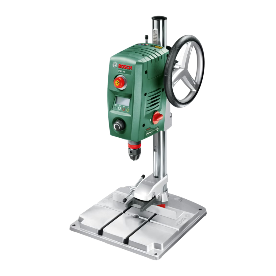
Product Features


- Base plate
- Quick-clamping lever
- Quick-clamping device
- Drilling column
- Rack
- Speed diagram
- Clamping lever of the height adjustment
- Clamping lever of depth stop
- Depth stop
- Laser warning label
- Handwheel
- Motor unit
- On/Off switch with Quick-Stop function
- Display
- Speed regulator
- Keyless chuck
- Tool bit*
- Mounting holes
- Parallel guide
- Wing bolts of the parallel guide
- Gear selector
- Illumination and laser unit
- Allen key (4 mm)
- Fastening screw of the drilling column
- Guide cog of the drilling column
- Guide groove of the base plate
- Securing ring
- Holding ring
- Clamping sleeve
- Illumination button
- Laser-cross button
- Button for speed indication/drilling-depth indication
- Zero-point button
- Set screws for clamping force of the brake
*Accessories shown or described are not part of the standard delivery scope of the product. A complete overview of accessories can be found in our accessories program.
Technical Data
| Drill Press | PBD 40 | ||||
| Article number | 3 603 M07 0.. | ||||
| Rated power input | W | 710 | |||
| No-load speed | 1st gear | min-1 | 200 –850 | ||
| 2nd gear | min-1 | 600 –2500 | |||
| Laser type | nm | 650 | |||
| mW | < 1 | ||||
| Laser class | 2 | ||||
| Max. drilling dia. | Steel | mm | 13 | ||
| Wood | mm | 40 | |||
| Chuck clamping range | mm | 1.5 –13 | |||
| Drill stroke, max. | mm | 90 | |||
| Total height | mm | 650 | |||
| Size of base plate (Width x depth x height) | mm | 330 x 350 x 30 | |||
| Weight according to EPTA-Procedure 01/2003 | kg | 11.2 | |||
| Protection class |  | ||||
| The values given are valid for a nominal voltage [U] of 230 V. For different voltages and models for specific countries, these values can vary. | |||||
Noise/Vibration Information
Measured sound values determined according to EN 61029.
Typically the A-weighted noise levels of the product are:
Sound pressure level 77 dB(A); Sound power level 90 dB(A).
Uncertainty K =3 dB.
Wear hearing protection!
Vibration total values ah (triax vector sum) and uncertainty K determined according to EN 61029: ah<2.5 m/s2, K=1.5 m/s2.
The vibration emission level given in this information sheet has been measured in accordance with a standardised test given in EN 61029 and may be used to compare one tool with another. It may be used for a preliminary assessment of exposure.
The declared vibration emission level represents the main applications of the tool. However if the tool is used for different applications, with different accessories or poorly maintained, the vibration emission may differ. This may significantly increase the exposure level over the total working period. An estimation of the level of exposure to vibration should also take into account the times when the tool is switched off or when it is running but not actually doing the job. This may significantly reduce the exposure level over the total working period.
Identify additional safety measures to protect the operator from the effects of vibration such as: maintain the tool and the accessories, keep the hands warm, organisation of work patterns.
Assembly
- Avoid unintentional starting of the machine. During assembly and for all work on the machine, the power plug must not be connected to the mains supply.
Delivery Scope
Before starting the operation of the machine for the first time, check if all parts listed below have been supplied:
- Motor unit 12 with drilling column 4
- Base plate 1
- Quick-clamping device 3
- Parallel guide 19
- Allen key 23
Note: Check the power tool for possible damage.
Before further use of the machine, check that all protective devices are fully functional. Any lightly damaged parts must be carefully checked to ensure flawless operation of the tool. All parts must be properly mounted and all conditions fulfilled that ensure faultless operation.
Damaged protective devices and parts must be immediately replaced by an authorised service centre.
Mounting Individual Components
(see figure A)
Before putting into operation for the first time, the machine must be assembled as follows:

- Slide the quick-clamping device 3 over the drilling column 4.
- Insert the drilling column 4 into the base plate 1 in such a manner that the guide cog 25 engages in the guide groove 26.
- Firmly tighten fastening screw 24 with Allen key 23.
Mounting to a Working Surface
(see figure B)
- To ensure safe handling, the machine must be mounted on a level and stable surface (e. g., workbench) prior to using.
- Fasten the power tool with suitable screw fasteners to the working surface. The mounting holes 18 serve for this purpose.

- Fasten the power tool with suitable screw fasteners to the working surface. The mounting holes 18 serve for this purpose.

Dust/Chip Extraction
Dusts from materials such as lead-containing coatings, some wood types, minerals and metal can be harmful to one's health. Touching or breathing-in the dusts can cause allergic reactions and/or lead to respiratory infections of the user or bystanders.
Certain dusts, such as oak or beech dust, are considered as carcinogenic, especially in connection with wood-treatment additives (chromate, wood preservative). Materials containing asbestos may only be worked by specialists.
- As far as possible, use a dust extraction system suitable for the material.
- Provide for good ventilation of the working place.
- It is recommended to wear a P2 filter-class respirator.
Observe the relevant regulations in your country for the materials to be worked.
- Prevent dust accumulation at the workplace. Dusts can easily ignite.
Changing the Tool
(see figure C)
The motor unit 12 is provided ex works with a dual-sleeve keyless chuck 16.

Inserting
- Turn the securing ring 27 toward "UNLOCK".
- Turn the clamping sleeve 29 clockwise until the tool bit 17 can be inserted.
- Fully insert the tool bit 17, hold it in the tool holder and turn the clamping sleeve 29 anticlockwise firmly by hand to tighten it.
Firmly hold the holding ring 28 when doing this. - Turn the securing ring 27 toward "LOCK"
Note: When inserting drill bits with small diameters, set the tool holder beforehand approximately to the drill bit diameter. Otherwise, it is possible that the drill bit is not inserted centred.
Removing
- Turn the securing ring 27 toward "UNLOCK".
- Turn the clamping sleeve 29 clockwise until the tool bit 17 can be removed.
Operation
- Before any work on the machine itself, pull the mains plug.
- After each adjustment on the machine, retighten the screws and clamping levers.
Preparing for Operation
Illuminating the Work Area

(see figure D)
Provide for sufficient lighting of the direct working area.
- To activate the display 14, turn the On/Off switch 13 to position
![]() .
. - Switch on the illumination unit 22 with button 30. The indication "Light" is shown on display 14.
 .
.Correctly positioning the workpiece

(see figure E)
A laser cross indicates the exact drilling location.
- To activate the display 14, turn the On/Off switch 13 to position
![]() .
. - Switch on the laser unit 22 with button 31.
The indication "Laser" is shown on display 14. - Align your mark on the workpiece with the laser cross.
Clamping the Workpiece

(see figures F1 – F2)
To ensure optimum working safety, the workpiece must always be firmly clamped.
Do not saw workpieces that are too small to clamp.
- Position the workpiece with help of the laser cross (see "Correctly positioning the workpiece").
- Loosen the quick-clamping lever 2 on the quick-clamping device 3.
- Allow the quick-clamping device to face against the workpiece. Turn the quick-clamping lever 2 in clockwise direction until the workpiece is firmly clamped.
- After drilling, loosen quick-clamping lever 2 in anticlockwise direction.
- Turn the quick-clamping device 3 aside and remove the workpiece.
The parallel guide 19 is used for securing larger workpieces against turning.
- Loosen the wing bolts 20 of parallel guide 19 and insert the parallel guide into the grooves of base plate 1.
- Retighten the wing bolts again.
- Clamp the workpiece with the quick-clamping device3.
Note: Use a machine vice (e.g. Bosch MS 80) to clamp smaller workpieces.
Adjusting the Height of the Motor Unit

(see figure G)
- Do not adjust the height of the motor unit during operation. Actuate clamping lever 7 only when the handwheel is in the starting position. This safety measure prevents possible injury.
The height of the motor unit 12 can be adjusted dependent on the length of the application tool and the size of the workpiece.
Note: After adjusting the height of the motor unit, the positioning of the workpiece must be checked again with the laser cross. Realign the workpiece, if required.
When clamping lever 7 is open, a brake prevents the motor unit 12 from accidental lowering. Occasionally check the clamping force of the brake and readjust it as required (see "Adjusting the Brake of the Motor Unit").
- Make sure that the handwheel 11 is in the starting position.
- Grasp the handwheel 11 with one hand and with the other hand, loosen clamping lever 7 in anticlockwise direction.
- Adjust the height of motor unit 12 with the handwheel according to the inserted application tool and height of the workpiece.
- Tighten clamping lever 7 again in clockwise direction.
Note: Clamping lever 7 is indexed (adjustable), allowing it to be set to an ergonomically favourable and space-saving position.
With the clamping lever tightened, pull its lever away from the motor unit, turn it to the desired position and allow it to engage again.
Starting Operation
- Observe correct mains voltage! The voltage of the power source must agree with the voltage specified on the nameplate of the machine. Power tools marked with 230 V can also be operated with 220 V.
Switching On
To save energy, only switch the power tool on when using it.
- To activate the display 14, turn the On/Off switch 13 to position
![]() .
. - To start the machine, turn the On/Off switch 13 to position
![]() .
.
The speed can now be set (see "Adjusting the Speed").
 .
.Switching Off
- To end the drilling, turn the On/Off switch 13 to position.
or - To completely shut-off the machine, turn the On/Off switch 13 to position "0".
Note: The power tool is now currentless. All current settings are deleted.
Quick-Stop Function
The Quick-Stop function enables swift switching off, e.g., when the application tool is jammed or locked-up in the workpiece.
- Briefly and quickly press the On/Off switch 13.
The machine and the display are switched off immediately.
Note: The power tool is now currentless. All current settings are deleted. - To restart the operation of the machine afterwards, the On/Off switch 13 must be reset to position "0".
Afterwards, the machine can be switched on again (On/Off switch 13 in position![]() ).
).
Restarting Protection
The restarting protection prevents uncontrolled starting of the machine after a power failure (e.g., when the mains plug is pulled during operation).
- To restart the operation of the machine afterwards, the On/Off switch 13 must be reset to position
![]() .
.
Afterwards, the machine can be switched on again (On/Off switch 13 in position![]() ).
).
Temperature Dependent Overload Protection
When using the machine as intended for, it cannot be subject to overload. In case of excessive loading or when exceeding the allowable operating temperature, the electronics switch the machine off until it is in the optimal operating-temperature range again.
- To restart the operation of the machine afterwards, the On/Off switch 13 must be reset to position
![]() . Afterwards, the machine can be switched on again (On/Off switch 13 in position
. Afterwards, the machine can be switched on again (On/Off switch 13 in position ![]() ).
).
Adjusting the Speed
- Set the correct speed before beginning to work. The speed must be appropriate for the drilling diameter and the material being drilled. When the speed is set incorrectly, the application tool can become caught or jam in the workpiece.
When adjusting the appropriate speed, please refer to the speed diagram 6.
The diagram provides the speed (rpm) to be set dependent on the drill bit diameter (Ø in mm) for the materials Steel and Aluminium.
Mechanical gear selection
Actuate the gear selector 21 only when the machine is at a standstill.
Two speed ranges can be preselected with the gear selector 21.
1st gear:
Low speed range; for working with large drilling diameters.
2nd gear:
High speed range; For working with small drilling diameters.
- Set the gear selector 21 to the desired position.
Note: If the gear selector 21 cannot be turned to the stop, turn the drill chuck a little.
Electronic Speed Control

(see figure H)
With the speed regulator 15, the speed of the machine can be variably adjusted.
- To start the machine, turn the On/Off switch 13 to position
![]() .
. - Press button 32 until "Speed" is indicated on the display.
- Turn the speed regulator 15 until the desired speed is indicated on display 14.
Working Advice
General Information
Before drilling, make sure that the quick-clamping device 3, the parallel guide 19 or the machine vice (accessory) are firmly clamped/tightened.
When the drill bit comes out of the workpiece, it can become caught or jam in the workpiece, and drag the workpiece along. Therefore, reduce the feed at the end of the drilling phase.
If the application tool should become blocked, switch the machine off. Allow the application tool and the workpiece to cool down. Remove the drilling chips/swarf. Determine the cause of the application tool's jam and correct it.
Special Notes on Drilling in Metal
Centre-punch metal workpieces.
Pilot-drill when drilling diameters in excess of 10 mm.
To improve your work, use cutting oil (e.g. Bosch universal cutting oil) to cool the drilling.
Position of the Operator
- Position yourself in front of the machine. This ensures a good view of the drilling location.
- Keep your hands and fingers away from the rotating application tool.
- Do not stand in front of the motor unit with crossed arms.
Drilling
- Place the workpiece on base plate 1.
- Adjust the height of the motor unit (see "Adjusting the Height of the Motor Unit").
- Align the workpiece with help of the laser cross (see "Correctly positioning the workpiece").
- Firmly clamp the workpiece (see "Clamping the Workpiece").
- Adjust the appropriate speed (see "Adjusting the Speed").
- Switch on the machine.
- For drilling, turn handwheel 11 with uniform feed until the desired drilling depth is reached (see "Indicating the Drilling Depth").
- Once the desired drilling depth is reached, guide handwheel 11 back until the motor unit is back in the starting position.
- Switch the power tool off.
Indicating the Drilling Depth

(see figure I)
The current drilling depth can be indicated on the display 14.
- After the speed has been set, press button 32 until "Depth" is indicated on the display.
- Adjust the height of the motor unit (see "Adjusting the Height of the Motor Unit").
- Carefully allow the drill-bit tip to slightly touch the workpiece.
- Press button 33 to set the zero point.
The indication "Reset" is shown on display 14. - Drill with uniform feed until the desired drilling depth is indicated on the display.
Adjusting the Drilling Depth

(see figure J)
With the depth stop 9, the drilling depth t can be determined.
- Loosen clamping lever 8 in anticlockwise direction.
- Carry out a test drilling. When the desired drilling depth is indicated on display 14 (see "Indicating the Drilling Depth"), retighten clamping lever 8 again. For the following drillings, the drilling depth is limited to the setting t.
Transport
- When transporting the machine, hold it by the base plate 1.
- The power tool should always be carried by two persons in order to avoid back injuries.
Maintenance and Service
Maintenance and Cleaning
- Before any work on the machine itself, pull the mains plug.
- For safe and proper working, always keep the machine and ventilation slots clean.
If required, clean the drilling column 4 with a dry cloth and apply a light coat of Bosch universal cutting oil (accessory).
If the replacement of the supply cord is necessary, this has to be done by Bosch or an authorized Bosch service agent in order to avoid a safety hazard.

Adjusting the Brake of the Motor Unit (see figure K)
The clamping force of the brake for the motor unit 12 can be readjusted.
Checking:
- The clamping force of the brake must securely hold the motor unit in any position.
Adjusting:
- Turn both set screws 34 in anticlockwise direction with the supplied Allen key 23 to reduce the clamping force, or increase the clamping force by turning in clockwise direction.
Tighten both set screws uniformly. - Check if the desired clamping force has been reached.
After-sales Service and Application Service
In all correspondence and spare parts order, please always include the 10-digit article number given on the type plate of the machine.
Our after-sales service responds to your questions concerning maintenance and repair of your product as well as spare parts. Exploded views and information on spare parts can also be found under:
www.bosch-pt.com
Bosch's application service team will gladly answer questions concerning our products and their accessories
Great Britain
Robert Bosch Ltd. (B.S.C.)
P.O. Box 98
Broadwater Park
North Orbital Road
Denham
Uxbridge
UB 9 5HJ
Tel. Service: (0844) 7360109
Fax: (0844) 7360146
E-Mail: boschservicecentre@bosch.com
Ireland
Origo Ltd.
Unit 23 Magna Drive
Magna Business Park
City West
Dublin 24
Tel. Service: (01) 4666700
Fax: (01) 4666888
Australia, New Zealand and Pacific Islands
Robert Bosch Australia Pty. Ltd.
Power Tools
Locked Bag 66
Clayton South VIC 3169
Customer Contact Center
Inside Australia:
Phone: (01300) 307044
Fax: (01300) 307045
Inside New Zealand:
Phone: (0800) 543353
Fax: (0800) 428570
Outside AU and NZ:
Phone: +61 3 95415555
www.bosch.com.au
Republic of South Africa
Customer service
Hotline: (011) 6519600
Gauteng – BSC Service Centre
35 Roper Street, New Centre
Johannesburg
Tel.: (011) 4939375
Fax: (011) 4930126
E-Mail: bsctools@icon.co.za
KZN – BSC Service Centre
Unit E, Almar Centre
143 Crompton Street
Pinetown
Tel.: (031) 7012120
Fax: (031) 7012446
E-Mail: bsc.dur@za.bosch.com
Western Cape – BSC Service Centre
Democracy Way, Prosperity Park
Milnerton
Tel.: (021) 5512577
Fax: (021) 5513223
E-Mail: bsc@zsd.co.za
Robert Bosch GmbH
Power Tools Division
70745 Leinfelden-Echterdingen
Germany
www.bosch-pt.com
Documents / Resources
References
Download manual
Here you can download full pdf version of manual, it may contain additional safety instructions, warranty information, FCC rules, etc.
Advertisement


Need help?
Do you have a question about the PBD 40 and is the answer not in the manual?
Questions and answers