Advertisement
About this guide
This user guide contains the information you need when installing and configuring the motherboard.
Where to find more information
Refer to the following sources for additional information and for product and software updates.
- ASUS website
The ASUS website (www.asus.com) provides updated information on ASUS hardware and software products. - Optional documentation
Your product package may include optional documentation, such as warranty flyers, that may have been added by your dealer. These documents are not part of the standard package. - MyASUS
MyASUS offers a variety of support features such as helping to troubleshoot issues, optimizing product performance, integrating ASUS software, and recovery drive creation. Please visit https://www.asus.com/support for installation guide and FAQ.
![information]() MyASUS is only available on selected models, please check your motherboard's specifications summary to see if your motherboard supports MyASUS.
MyASUS is only available on selected models, please check your motherboard's specifications summary to see if your motherboard supports MyASUS.
![]()
- Driver and Utilities FAQ
Please visit https://www.asus.com/support for more information on downloading and installing drivers and utilities for your motherboard.
![]()


Conventions used in this guide
To ensure that you perform certain tasks properly, take note of the following symbols used throughout this user guide.

Information to prevent damage to the components and injuries to yourself when trying to complete a task.

Instructions that you MUST follow to complete a task.
 NOTE: Tips and additional information to help you complete a task.
Package contents
Check your motherboard package for the following items.
| Motherboard | 1 x B760M-AYW WIFI motherboard |
| Cables | 2 x SATA 6Gb/s cables |
| Miscellaneous | 1 x ASUS Wi-Fi moving antennas 1 x I/O Shield 1 x M.2 Rubber package 1 x Screw package for M.2 SSD |
| Documentation | 1 x Quick start guide |
- If any of the above items is damaged or missing, contact your retailer.
- Items not listed in the Package contents list above are purchased separately and do not come bundled with your motherboard package.
B760M-AYW WIFI specifications summary
| CPU | Intel® Socket LGA1700 for Intel® Core™14th & 13th Gen Processors, Intel® Core™ 12th Gen, Pentium® Gold and Celeron® Processors* Supports Intel® Turbo Boost Technology 2.0 and Intel® Turbo Boost Max Technology 3.0** * Refer to www.asus.com for CPU support list. ** Intel® Turbo Boost Max Technology 3.0 support depends on the CPU types. |
| Chipset | Intel® B760 Chipset |
| Memory | 2 x DIMM slots, Max. 96GB, DDR5 Non-ECC, Un-buffered Memory* Dual Channel Memory Architecture Supports Intel® Extreme Memory Profile (XMP) memory module * Supported memory types, data rate (speed), and number of DRAM modules vary depending on the CPU and memory configuration, for more information please refer to CPU/Memory Support list under the Support tab of product information site or visit https://www.asus.com/support/. * Non-ECC, un-buffered DDR5 memory supports On-Die ECC function. |
| Graphics | 1 x HDMI™ port** * Graphics specifications may vary between CPU types. Please refer to www.intel.com for any updates. ** Supports 4K@60Hz as specified in HDMI 2.1. |
| Expansion Slots | Intel® Core™ Processors (14th & 13th & 12th Gen)
Intel® B760 Chipset
* To ensure compatibility of the device installed, please refer to https://www.asus.com/support/ for the list of supported peripherals. |
| Storage | Total supports 2 x M.2 slots and 4 x SATA 6Gb/s ports*
Intel® B760 Chipset
* I ntel® Rapid Storage Technology supports SATA RAID 0/1/5/10. |
| Ethernet | 1 x Realtek 2.5Gb Ethernet ASUS LANGuard |
| Wireless & Bluetooth® | Wi-Fi 6 (802.11 a/b/g/n/ac/ax) Supports 2.4/5GHz frequency band Bluetooth® v5.3* * The Bluetooth version may vary, please refer to the Wi-Fi module manufacturer's website for the latest specifications. |
| USB | Rear USB (Total 6 ports) 4 x USB 3.2 Gen 1 ports (4 x Type-A) 2 x USB 2.0 ports (2 x Type-A) Front USB (Total 4 ports) 1 x USB 3.2 Gen 1 header supports 2 additional USB 3.2 Gen 1 ports 1 x USB 2.0 header supports 2 additional USB 2.0 ports |
| Audio | Realtek 7.1 Surround Sound High Definition Audio CODEC*
Audio Features
* A chassis with an HD audio module in the front panel is required to support 7.1 Surround Sound audio output. |
| Back Panel I/O Ports | 4 x USB 3.2 Gen 1 ports (4 x Type-A) 2 x USB 2.0 ports (2 x Type-A) 1 x HDMI™ port 1 x Wi-Fi Module 1 x Realtek 2.5Gb Ethernet port 3 x Audio jacks |
| Internal I/O connectors | Fan and Cooling Related 1 x 4-pin CPU Fan header 2 x 4-pin Chassis Fan headers Power Related 1 x 24-pin Main Power connector 1 x 8-pin +12V Power connector Storage Related 2 x M.2 slots (Key M) 4 x SATA 6Gb/s ports USB 1 x USB 3.2 Gen 1 header supports 2 additional USB 3.2 Gen 1 ports 1 x USB 2.0 header supports 2 additional USB 2.0 ports Miscellaneous 3 x Addressable Gen 2 headers 1 x Clear CMOS header 1 x COM Port header 1 x Front Panel Audio header (AAFP) 1 x S/PDIF Out header 1 x Speaker header 1 x SPI TPM header (14-1pin) 1 x 10⁻¹ pin System Panel header |
| Special Features | ASUS 5X PROTECTION III
ASUS Q-Design
ASUS Thermal Solution
ASUS EZ DIY
Aura Sync
|
| Software Features | ASUS Exclusive Software
AI Suite 3
MyASUS
|
| BIOS | 128 Mb Flash ROM, UEFI AMI BIOS |
| BIOS CAP Filename | B760M-AYW WIFI: B760MAW.CAP |
| Manageability | WOL by PME, PXE |
| Operating System | Windows® 11 Windows® 10 64-bit |
| Form Factor | mATX Form Factor 9.6 inch x 8.3 inch (24.4 cm x 21.1 cm) |
Specifications are subject to change without notice. Please refer to the ASUS website for the latest specifications.
Product Introduction
Before you proceed
Take note of the following precautions before you install motherboard components or change any motherboard settings.

- Unplug the power cord from the wall socket before touching any component.
- Before handling components, use a grounded wrist strap or touch a safely grounded object or a metal object, such as the power supply case, to avoid damaging them due to static electricity.
- Hold components by the edges to avoid touching the ICs on them.
- Whenever you uninstall any component, place it on a grounded antistatic pad or in the bag that came with the component.
- Before you install or remove any component, ensure that the power supply is switched off or the power cord is detached from the power supply. Failure to do so may cause severe damage to the motherboard, peripherals, or components.
- The pin definitions in this chapter are for reference only. The pin names depend on the location of the header/jumper/connector.
- The illustrations for this chapter are for reference only. The WiFi module is only available on selected models.
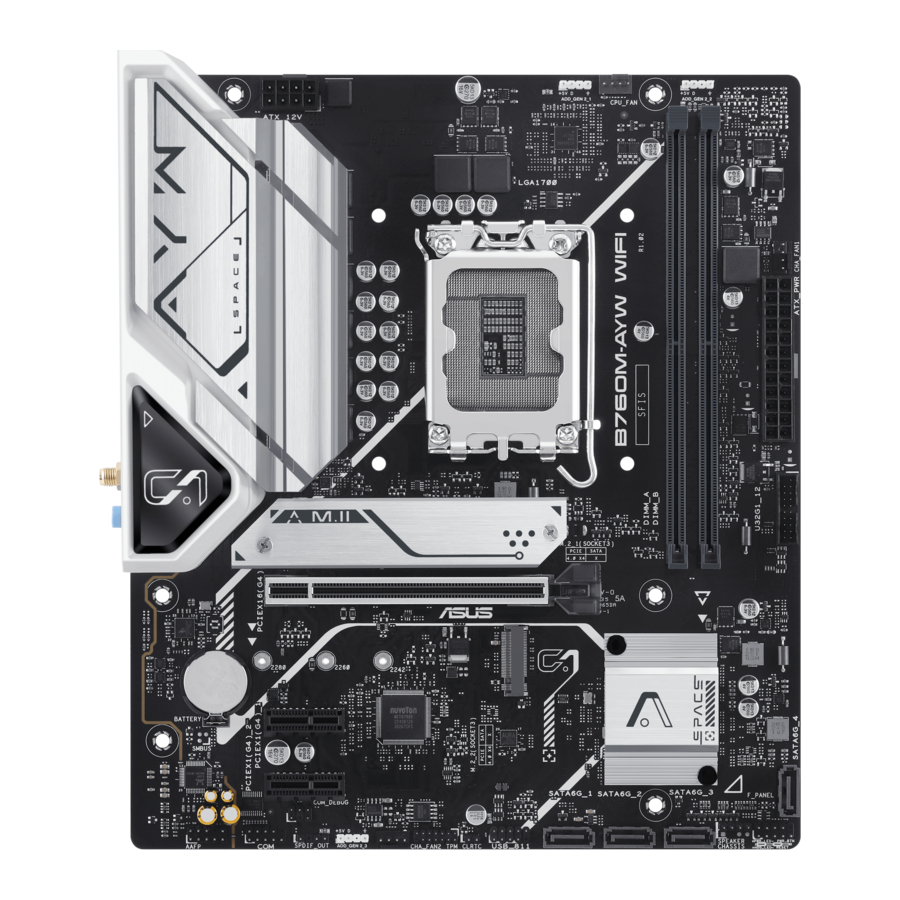
Motherboard layout

Layout contents
- CPU socket
The motherboard comes with a LGA1700 socket designed for Intel® Core™ 14th & 13th Gen Processors, Intel® Core™ 12th Gen, Pentium® Gold and Celeron® Processors.
![information]() For more details, refer to CPU installation.
For more details, refer to CPU installation. - DIMM slots
The motherboard comes with Dual Inline Memory Modules (DIMM) slots designed for DDR5 (Double Data Rate 5) memory modules.
![information]() For more details, refer to DIMM installation.
For more details, refer to DIMM installation. - Expansion slots
This motherboard supports one PCIe x16 graphics card and two PCIe x1 network cards, SCSI cards and other cards that comply with the PCI Express specification.
![]()

- Fan headers
The Fan headers allow you to connect fans to cool the system. - Power connectors
These Power connectors allow you to connect your motherboard to a power supply. The power supply plugs are designed to fit in only one orientation. Find the proper orientation and push down firmly until the power supply plugs are fully inserted.
![warning]() Ensure to connect the 8-pin power plug.
Ensure to connect the 8-pin power plug.
![]()
We recommend that you use a PSU with a higher power output when configuring a system with more power-consuming devices. The system may become unstable or may not boot up if the power is inadequate. - M.2 slots (Key M)
The M.2 slots allow you to install M.2 devices such as M.2 SSD modules.
![]()
- Intel ® Core™ Processors (14 th & 13 th & 12 th Gen)
M.2_1 slot (Key M), type 2242/2260/2280 (supports PCIe 4.0 x4 mode) - Intel ® B760 Chipset
M.2_2 slot (Key M), type 2242/2260/2280 (supports PCIe 4.0 x4 mode)
- Intel ® Core™ Processors (14 th & 13 th & 12 th Gen)
- SATA 6Gb/s ports
The SATA 6Gb/s ports allow you to connect SATA devices such as optical disc drives and hard disk drives via SATA cables. - USB 3.2 Gen 1 header
The USB 3.2 Gen 1 header allows you to connect a USB 3.2
Gen 1 module for additional USB 3.2 Gen 1 ports. The USB 3.2 Gen 1 header provides data transfer speeds of up to 5 Gb/s.
![]()
- USB 2.0 header
The USB 2.0 header allows you to connect a USB module for additional USB 2.0 ports. The USB 2.0 header provides data transfer speeds of up to 480 Mb/s.
DO NOT connect a 1394 cable to the USB connectors. Doing so will damage the motherboard!
![warning]() DO NOT connect a 1394 cable to the USB connectors. Doing so will damage the motherboard!
DO NOT connect a 1394 cable to the USB connectors. Doing so will damage the motherboard!
![]()
- Addressable Gen 2 headers
The Addressable Gen2 headers allow you to connect individually addressable RGB WS2812B LED strips or WS2812B based LED strips.
![warning]() Before you install or remove any component, ensure that the power supply is switched off or the power cord is detached from the power supply. Failure to do so may cause severe damage to the motherboard, peripherals, or components.
Before you install or remove any component, ensure that the power supply is switched off or the power cord is detached from the power supply. Failure to do so may cause severe damage to the motherboard, peripherals, or components.
![]()
![information]()
- The Addressable Gen2 header supports WS2812B addressable RGB LED strips (5V/ Data/Ground), with a maximum power rating of 3A (5V), and the addressable headers on this board can handle a combined maximum of 500 LEDs.
- Actual lighting and color will vary with LED strip.
- If your LED strip does not light up, check if the addressable RGB LED strip is connected in the correct orientation, and the 5V connector is aligned with the 5V header on the motherboard.
- The addressable RGB LED strip will only light up when the system is powered on.
- Clear CMOS header
The Clear CMOS header allows you to clear the Real Time Clock (RTC) RAM in the CMOS, which contains the date, time, system passwords, and system setup parameters. To erase the RTC RAM:
![]()
- Turn OFF the computer and unplug the power cord.
- Short-circuit pin 1-2 with a metal object or jumper cap for about 5-10 seconds.
- Plug the power cord and turn ON the computer.
- Hold down the <Del> key during the boot process and enter BIOS setup to reenter data.
![warning]() DO NOT short-circuit the pins except when clearing the RTC RAM. Short-circuiting or placing a jumper cap will cause system boot failure!
DO NOT short-circuit the pins except when clearing the RTC RAM. Short-circuiting or placing a jumper cap will cause system boot failure!
![information]() If the steps above do not help, remove the onboard button cell battery and short the two pins again to clear the CMOS RTC RAM data. After clearing the CMOS, reinstall the button cell battery.
If the steps above do not help, remove the onboard button cell battery and short the two pins again to clear the CMOS RTC RAM data. After clearing the CMOS, reinstall the button cell battery.


- COM Port header
The COM (Serial) Port header allows you to connect a COM port module. Connect the COM port module cable to this header, then install the module to a slot opening on the system chassis.
![]()

- Front Panel Audio header
The Front Panel Audio header is for a chassis-mounted front panel audio I/O module that supports HD Audio. Connect one end of the front panel audio I/O module cable to this header.
![]()
- S/PDIF Out header
The S/PDIF Out header allows you to connect the Sony/Philips Digital Interface (S/PDIF) Out module.
![]()
- Speaker header
The Speaker header allows you to connect the chassis-mounted system warning speaker. The speaker allows you to hear system beeps and warnings.
![]()
- SPI TPM header
This header supports a Trusted Platform Module (TPM) system with a Serial Peripheral Interface (SPI), allowing you to securely store keys, digital certificates, passwords, and data. A TPM system also helps enhance network security, protects digital identities, and ensures platform integrity.
![]()
- System Panel header
The System Panel header supports several chassis-mounted functions.
![]()


- System Power LED header (+PWR_LED-)
The 2-pin header allows you to connect the System Power LED. The System Power LED lights up when the system is connected to a power source, or when you turn on the system power, and blinks when the system is in sleep mode. - Storage Device Activity LED header (+HDD_LED-)
The 2-pin header allows you to connect the Storage Device Activity LED. The Storage Device Activity LED lights up or blinks when data is read from or written to the storage device or storage device add-on card. - Power Button/Soft-off Button header (PWR_BTN)
The 2-pin header allows you to connect the system power button. Press the power button to power up the system, or put the system into sleep or soft-off mode (depending on the operating system settings). - Reset button header (RESET)
The 2-pin header allows you to connect the chassis-mounted reset button. Press the reset button to reboot the system.
Rear panel connectors

- Realtek 2.5Gb Ethernet port*
- Audio jacks**
- USB 2.0 ports 5, 6
- HDMI™ port
- USB 3.2 Gen 1 Type-A ports 3, 4, 9, 10
- Wi-Fi module
* and **: Refer to the tables below for LAN port LEDs, and audio port definitions.
We strongly recommend that you connect your devices to ports with matching data transfer rate. For example connecting your USB 3.2 Gen 1 devices to USB 3.2 Gen 1 ports for faster and better performance for your devices.
* Realtek 2.5Gb Ethernet port LED indications

| Speed LED | |
| Status | Description |
| OFF | No link |
| GREEN | 2.5 Gbps connection |
| ORANGE | 1 Gbps / 100 Mbps / 10 Mbps connection |
| Activity Link LED | |
| Status | Description |
| OFF | No link |
| GREEN | Linked |
| BLINKING | Data activity |
** Audio 2, 4, 5.1 or 7.1-channel configuration
| Port | 2-channel | 4-channel | 5.1-channel | 7.1-channel |
| Rear panel | ||||
| LINE IN | - | Rear Speaker Out | Rear Speaker Out | Rear Speaker Out |
| LINE OUT | Front Speaker Out | Front Speaker Out | Front Speaker Out | Front Speaker Out |
| MIC IN | - | Center/ Subwoofer | Center/ Subwoofer | |
| Front panel | ||||
| HEADPHONE (Lime) | - | - | - | Side Speaker Out |
| MIC IN (Pink) | - | - | - | - |
CPU installation
- Ensure that you install the correct CPU designed for LGA1700 socket only. DO NOT install a CPU designed for LGA1155, LGA1156, LGA1151, and LGA1200 sockets on the LGA1700 socket.
- The CPU fits in only one correct orientation. DO NOT force the CPU into the socket to prevent bending the connectors on the socket and damaging the CPU.
- Ensure that all power cables are unplugged before installing the CPU.
- Upon purchase of the motherboard, ensure that the PnP cap is on the socket and the socket contacts are not bent. Contact your retailer immediately if the PnP cap is missing, or if you see any damage to the PnP cap/socket contacts/motherboard components. ASUS will shoulder the cost of repair only if the damage is shipment/ transit-related.
Install a heatsink or AIO cooler after installing the CPU. Please refer to the Motherboard Installation Guide on the ASUS support site, or to the user manual of the heatsink/AIO cooler for steps on installing the heatsink/AIO cooler.

Take caution when lifting the load lever, ensure to hold onto the load lever when releasing the load lever. Letting go of the load lever immediately after releasing it may cause the load lever to spring back and cause damage to your motherboard

DIMM installation
The figure illustrates the location of the DDR5 DIMM sockets

A DDR5 memory module is notched differently from a DDR, DDR2, DDR3, or DDR4 module. DO NOT install a DDR, DDR2, DDR3, or DDR4 memory module to the DDR5 slot.
Recommended memory configurations

You may install Non-ECC DDR5 DIMMs into the DIMM sockets.
- You may install varying memory sizes in the DIMM channels. The system maps the total size of the lower-sized channel for the dual-channel configuration. Any excess memory from the higher-sized channel is then mapped for single-channel operation.
- The default memory operation frequency is dependent on its Serial Presence Detect (SPD), which is the standard way of accessing information from a memory module. Under the default state, some memory modules for overclocking may operate at a lower frequency than the vendor-marked value.
- For system stability, use a more efficient memory cooling system to support a full memory load or overclocking condition.
- Always install the DIMMS with the same CAS Latency. For an optimum compatibility, we recommend that you install memory modules of the same version or data code (D/C) from the same vendor. Check with the vendor to get the correct memory modules.
- Visit the ASUS website for the latest QVL.
Installing a DIMM

DIMM removal

Wi-Fi moving antenna installation
Installing the ASUS Wi-Fi moving antenna
Connect the bundled ASUS Wi-Fi moving antenna connector to the Wi-Fi ports at the back of the chassis.

- Ensure that the ASUS Wi-Fi moving antenna is securely installed to the Wi-Fi ports.
- Ensure that the antenna is at least 20 cm away from all persons.
The illustration above is for reference only. The I/O port layout may vary with models, but the Wi-Fi moving antenna installation procedure is the same for all models.
BIOS and RAID Support
For more details on BIOS and RAID configurations, please refer to Manual & Document under the Support tab of the product information site, or visit https://www.asus.com/support.
Knowing UEFI BIOS
BIOS (Basic Input and Output System) stores system hardware settings such as storage device configuration, overclocking settings, advanced power management, and boot device configuration that are needed for system startup in the motherboard CMOS. In normal circumstances, the default BIOS settings apply to most conditions to ensure optimal performance. DO NOT change the default BIOS settings except in the following circumstances:
- An error message appears on the screen during the system bootup and requests you to run the BIOS Setup.
- You have installed a new system component that requires further BIOS settings or update.
Inappropriate BIOS settings may result to instability or boot failure. We strongly recommend that you change the BIOS settings only with the help of a trained service personnel.
BIOS settings and options may vary due to different BIOS release versions. Please refer to the latest BIOS version for settings and options.
Entering BIOS at startup
To enter BIOS Setup at startup, press <Delete> or <F2> during the Power-On Self Test (POST). If you do not press <Delete> or <F2>, POST continues with its routines.
- If the system becomes unstable after changing any BIOS setting, load the default settings to ensure system compatibility and stability. Select theLoad Optimized Defaults item under the Exit menu or press the <F5> hotkey.
- If the system fails to boot after changing any BIOS setting, try to clear the CMOS and reset the motherboard to the default value.
- The BIOS setup program does not support Bluetooth devices.
BIOS menu screen
The BIOS Setup program can be used under two modes: EZ Mode and Advanced Mode.
You can change modes from Setup Mode in Boot menu or by pressing the <F7> hotkey.
ASUS EZ Flash 3
The ASUS EZ Flash 3 feature allows you to update the BIOS without using an OS-based utility.
Ensure to load the BIOS default settings to ensure system compatibility and stability.
Select the Load Optimized Defaults item under the Exit menu or press the<F5> hotkey.
To update the BIOS:
- This function can support devices such as a USB flash disk with FAT 32/16 format and single partition only.
- DO NOT shut down or reset the system while updating the BIOS to prevent system boot failure!
- Insert the USB flash disk that contains the latest BIOS file to the USB port.
- Enter the Advanced Mode of the BIOS setup program. Go to theTool menu to select ASUS EZ Flash 3 Utility and press <Enter>.
- Press the Left arrow key to switch to theDrive field.
- Press the Up/Down arrow keys to find the USB flash disk that contains the latest BIOS, and then press <Enter>.
- Press the Right arrow key to switch to theFolder field.
- Press the Up/Down arrow keys to find the BIOS file, and then press <Enter> to perform the BIOS update process. Reboot the system when the update process is done.
ASUS CrashFree BIOS 3
The ASUS CrashFree BIOS 3 utility is an auto recovery tool that allows you to restore the BIOS file when it fails or gets corrupted during the updating process. You can restore a corrupted BIOS file using a USB flash drive that contains the BIOS file.
Recovering the BIOS
- Download the latest BIOS version for this motherboard from https://www.asus.com/support/.
- Rename the file using one of the following methods:
- Launch the BIOSRenamer.exe application to automatically rename the file.
- Manually rename the file to the BIOS CAP filename specified in theSpecifications summary section.
- Manually rename the file toasus.cap.
- Copy the renamed file to your USB storage device.
- Turn on the system.
- Insert the USB flash drive containing the BIOS file to a USB port.
- The utility automatically checks the devices for the BIOS file. When found, the utility reads the BIOS file and enters ASUS EZ Flash 3 automatically.
- The system requires you to enter BIOS Setup to recover the BIOS setting. To ensure system compatibility and stability, we recommend that you press the <F5> hotkey to load default BIOS values.
DO NOT shut down or reset the system while updating the BIOS! Doing so may cause system boot failure!
RAID configurations
The motherboard supports RAID configurations.
RAID definitions
RAID 0 (Data striping) optimizes two identical hard disk drives to read and write data in parallel, interleaved stacks. Two hard disks perform the same work as a single drive but at a sustained data transfer rate, double that of a single disk alone, thus improving data access and storage. Use of two new identical hard disk drives is required for this setup.
RAID 1 (Data mirroring) copies and maintains an identical image of data from one drive to a second drive. If one drive fails, the disk array management software directs all applications to the surviving drive as it contains a complete copy of the data in the other drive. This RAID configuration provides data protection and increases fault tolerance to the entire system. Use two new drives or use an existing drive and a new drive for this setup. The new drive must be of the same size or larger than the existing drive.
RAID 5 stripes both data and parity information across three or more hard disk drives. Among the advantages of RAID 5 configuration include better HDD performance, fault tolerance, and higher storage capacity. The RAID 5 configuration is best suited for transaction processing, relational database applications, enterprise resource planning, and other business systems. Use a minimum of three identical hard disk drives for this setup.
RAID 10 is data striping and data mirroring combined without parity (redundancy data) having to be calculated and written. With the RAID 10 configuration you get all the benefits of both RAID 0 and RAID 1 configurations. Use four new hard disk drives or use an existing drive and three new drives for this setup.
Service and Support
Visit our multi-language website at https://www.asus.com/support.

Product Register
Log in and register your device for better product support.

Safety information
Electrical safety
- To prevent electrical shock hazard, disconnect the power cable from the electrical outlet before relocating the system.
- When adding or removing devices to or from the system, ensure that the power cables for the devices are unplugged before the signal cables are connected. If possible, disconnect all power cables from the existing system before you add a device.
- Before connecting or removing signal cables from the motherboard, ensure that all power cables are unplugged.
- Seek professional assistance before using an adapter or extension cord. These devices could interrupt the grounding circuit.
- Ensure that your power supply is set to the correct voltage in your area. If you are not sure about the voltage of the electrical outlet you are using, contact your local power company.
- If the power supply is broken, do not try to fix it by yourself. Contact a qualified service technician or your retailer.
Operation safety
- Before installing the motherboard and adding devices on it, carefully read all the manuals that came with the package.
- Before using the product, ensure all cables are correctly connected and the power cables are not damaged. If you detect any damage, contact your dealer immediately.
- To avoid short circuits, keep paper clips, screws, and staples away from connectors, slots, sockets and circuitry.
- Avoid dust, humidity, and temperature extremes. Do not place the product in any area where it may become wet.
- Place the product on a stable surface.
- If you encounter technical problems with the product, contact a qualified service technician or your retailer.
- Your motherboard should only be used in environments with ambient temperatures between 10°C and 35°C.
Button/Coin Batteries Safety Information


KEEP OUT OF REACH OF CHILDREN
Swallowing can lead to chemical burns, perforation of soft tissue, and death. Severe burns can occur within 2 hours of ingestion. Seek medical attention immediately.

Documents / Resources
References
Download manual
Here you can download full pdf version of manual, it may contain additional safety instructions, warranty information, FCC rules, etc.
Advertisement


Need help?
Do you have a question about the B760M-AYW WIFI and is the answer not in the manual?
Questions and answers