
Acer Swift Go 14 (SFG14-72, SFG14-72T) Manual
- User manual (80 pages) ,
- Lifecycle extension manual (44 pages) ,
- Manual (43 pages)
Advertisement

Self-Repair
This chapter highlights the limited self-repair capabilities of the product.
Prior performing self-repair, familiarize yourself with the Safety Guidelines and Recommended Equipment sections first as described in the chapter "Disassembly Procedures".
Depending on model, the following key components are eligible for self-repair (if applicable);
- Battery pack
- HDD / SSD module
- DIMM module(s)
- WLAN module
- LTE module
If a particular key component is listed and thus would be eligible for self-repair, but is not described in the "Disassembly Procedures" section, then this component is either not present on the respective model, or it is present but embedded on the motherboard and therefore not eligible for self-repair.

Do not attempt to replace other components than those listed above.

For replacement parts, always use only Acer certified components in order to safeguard quality, optimum system performance, stability and reliability of the product.

Any damage to the product that occur during self-repair, or which has occurred as a result of a careless or unsuccessful self-repair attempt, is not covered by the standard product warranty.
Disassembly Procedures
Please refer to the chapter "Disassembly Procedures" for step by step disassembly instructions.
System BIOS & Driver Updates
Visit http://www.acer.com/support to discover the available system BIOS and Drivers for this product. After selecting the desired country/language, either enter the model name or product serial number, or select the product from the list of suggested models in order to get access to productspecific software and documentation.
To update the system BIOS:
- Download the desired system BIOS version from the website
- Unzip the downloaded file to your computer
- Double-click the extracted file in order to initiate the update process
- The update process itself is fully automated and its progress is visualized by means of a progress indicator
- A visual notification is shown when the update is complete

Upgrading the system BIOS incorrectly, or intermittence of the system BIOS update process could harm the product.

System BIOS upgrades or downgrades, if not performed by an Acer Service Center or authorized Service Partner, are at own risk.
To update Drivers:
Run Windows Update in order to get the latest drivers from Acer:
- Select the Start
![]() button
button - Go to Settings
![]() > Update & Security
> Update & Security ![]() > Windows Update
> Windows Update ![]()
- Available Drivers will automatically be listed on the screen. Press Download to start the download of the respective driver
- Installation of the driver will start automatically once the download is completed
Software Recovery
This product has embedded software recovery tools which can be used to either perform a partial or full software recovery, but also to create a Factory Default recovery media.
For more information about the software recovery options, how to perform a software recovery or creating a Factory Default recovery media, please refer to the chapter "Recovery" which is available in the User Manual of the product.

In the event of not being able to create a Factory Default recovery media, it is possible to obtain a copy of the recovery media through Acer Customer Service (http://www.acer.com/support)
This is not a free of charge service.
Safety Guidelines
This chapter contains step by step procedures on how to remove and de-install components from the computer. Use the following safety guidelines to ensure your personal safety. Each procedure included in this chapter assumes that you are preparing your computer for recycling and disposal. By performing any of these procedures you acknowledge that any remaining warranty applicable to your computer will be voided. Before you start any of the procedures in this chapter, make sure to read the following safety guidelines and the respective instructions within the chapter.
- Turn off your computer and disconnect all power sources before opening the computer cover or panels.
- To avoid electrostatic discharge, ground yourself by using a wrist grounding strap or by periodically touching an unpainted metal surface at the same time as touching a connector on the back of the computer.
- Take off any metal objects on your arms or fingers such as bracelets, rings or watches and make sure your hands are completely dry. Even if your unit is unplugged, there may still be some remaining electric charge.
- If a component does not come out easily, do not forcefully remove it. Instead, check that you are removing it correctly and that no wires or other parts are in the way.
- When you disconnect a cable, pull on its connector or on its pull-tab, not on the cable itself. Some cables have connectors with locking tabs; if you are disconnecting this type of cable, press in on the locking tabs before you disconnect the cable.
Recommended Equipment
The following tools are required to perform maintenance on the notebook:
- Wrist grounding strap and conductive mat
- Flat screwdriver
- Philips screwdriver
- Pointed plastic pry or similar object
- Tweezers
WEEE Annex VII Component
These components are classified as requiring selective treatment:
- Battery pack
- SSD modules
- WLAN module
- USB board
- Touchpad module
- RTC battery
- Mainboard
- LCD panel
Getting Started
Perform the following prior to performing any maintenance procedures:
- Place the system on a flat work surface.
- Make sure the system is completely powered down.
- If the device is in powered up mode, shut down the system normally.
- If the device is in sleep mode, wait for the Home Screen to clear. Then, shut down normally.
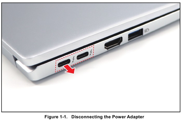
- Disconnect the AC Adapter and remove all cables from the system and its peripherals.
![Acer - Swift Go 14 - Getting Started Getting Started]()
Lower Case Removal
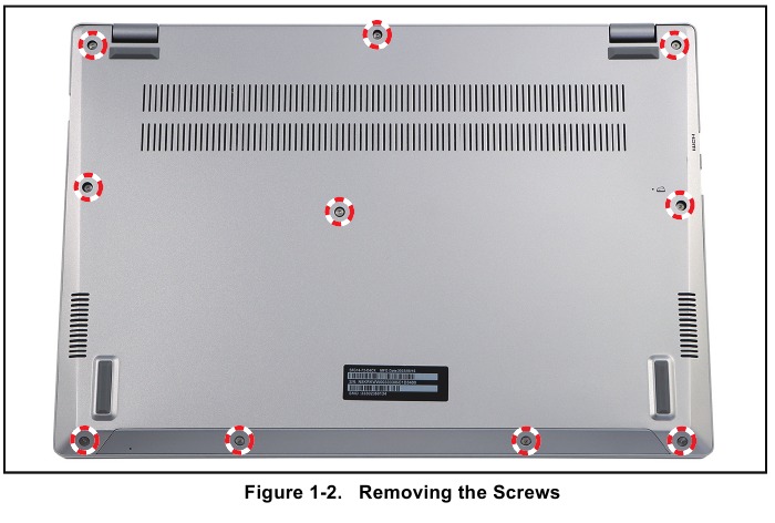
- Remove the ten (10) screws securing the lower case to the upper case.
![Acer - Swift Go 14 - Lower Case Removal - Step 1 Lower Case Removal - Step 1]()
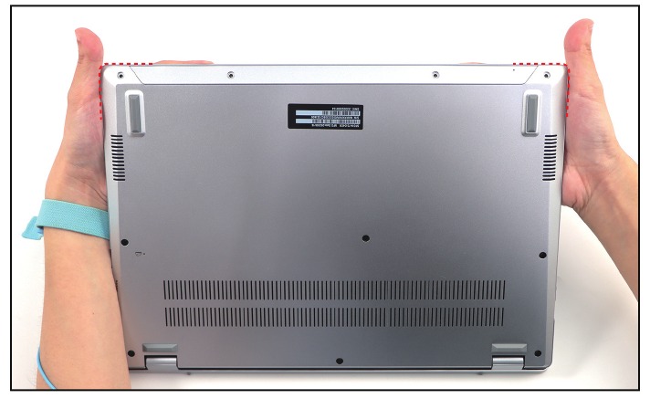
- By holding the lower case assembly upright, pry the lower case from the bottom side to release both edges latches.
![Acer - Swift Go 14 - Lower Case Removal - Step 2 Lower Case Removal - Step 2]()
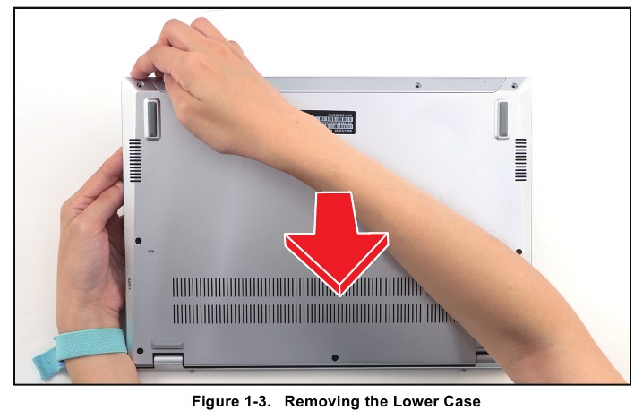
- Continue releasing the remaining latches. Then remove the lower case.
![Acer - Swift Go 14 - Lower Case Removal - Step 3 Lower Case Removal - Step 3]()
Table 1-1. Lower Case Screws
| Screw Name | Screw Type | Torque | Quantity |
| M 2.0 x 6.0 |  | 2.0~2.5kgf.cm | 10 |
Battery Removal
Prerequisite:
Lower Case Removal
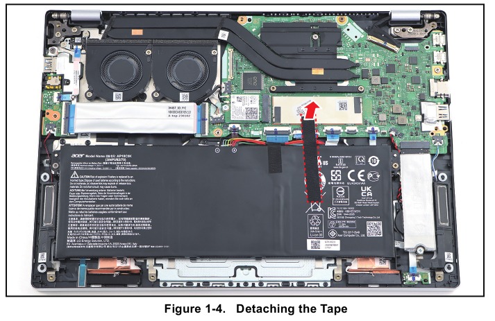
- Detach the tape securing the battery cable.
![Acer - Swift Go 14 - Battery Removal - Step 1 Battery Removal - Step 1]()
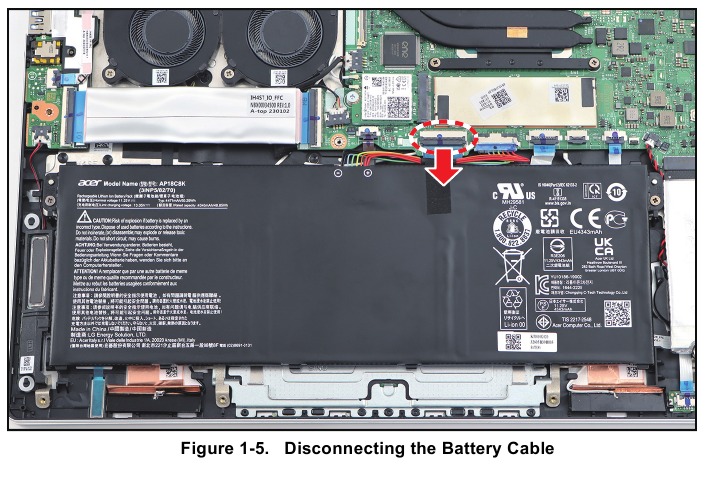
- Disconnect the battery cable from the mainboard connector.
![Acer - Swift Go 14 - Battery Removal - Step 2 Battery Removal - Step 2]()
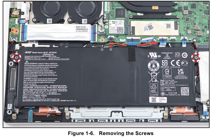
- Remove the two (2) screws securing the battery to the upper case.
![Acer - Swift Go 14 - Battery Removal - Step 3 Battery Removal - Step 3]()
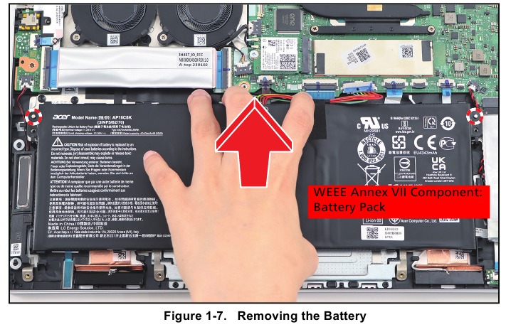
- Lift the battery to release it from the guide pins. Then remove the battery from the upper case.
![Acer - Swift Go 14 - Battery Removal - Step 4 Battery Removal - Step 4]()
Table 1-2. Battery Screws
| Screw Name | Screw Type | Torque | Quantity |
| M 2.0 x 4.0 |  | 1.8~2.2kgf.cm | 2 |
LCD Module Removal
Prerequisite: Battery Removal
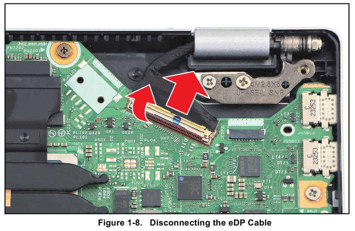
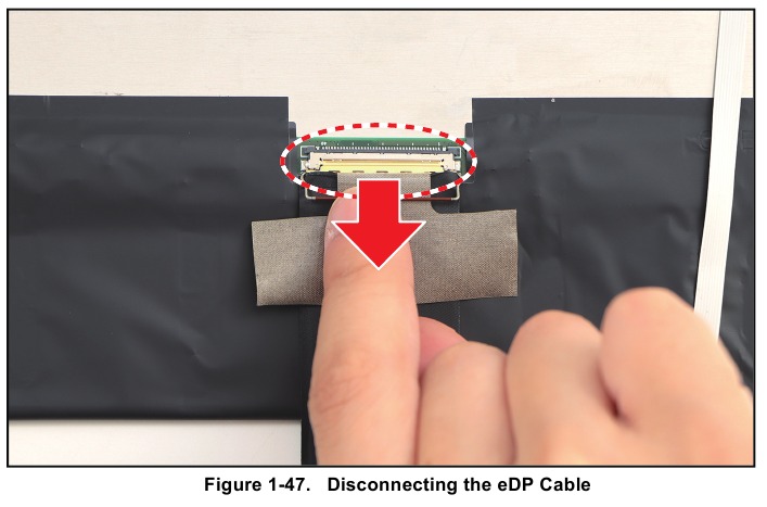
- Lift to open the latch securing the eDP cable. Then disconnect the eDP cable from the mainboard connector.
![Acer - Swift Go 14 - LCD Module Removal - Step 1 LCD Module Removal - Step 1]()
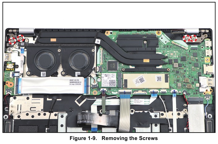
- Remove the four (4) screws securing the hinges and LCD module to the upper case.
![Acer - Swift Go 14 - LCD Module Removal - Step 2 LCD Module Removal - Step 2]()
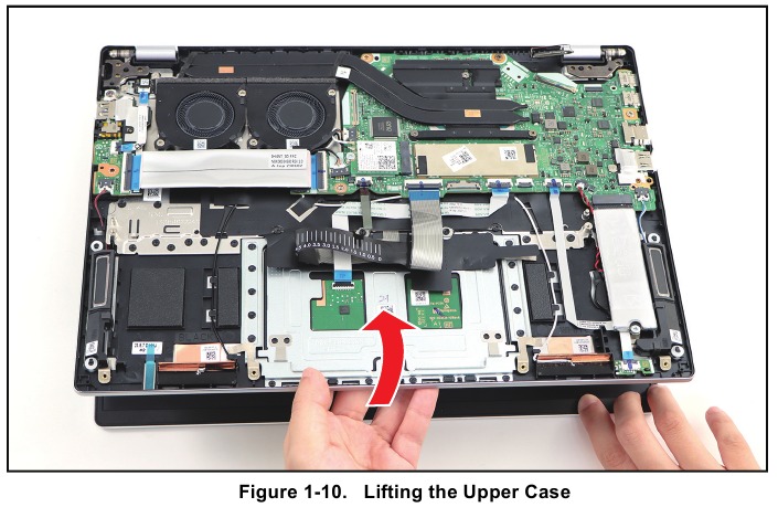
- Lift the upper case until it is fully open.
![Acer - Swift Go 14 - LCD Module Removal - Step 3 LCD Module Removal - Step 3]()
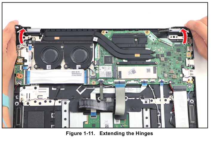
- Close the upper case. Then lift both hinges until they are fully extended.
![Acer - Swift Go 14 - LCD Module Removal - Step 4 LCD Module Removal - Step 4]()
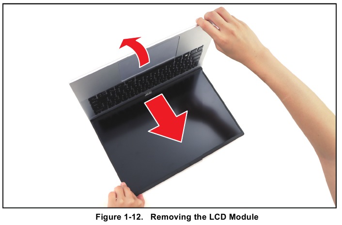
- Open the upper case again. Then remove the LCD module away from the upper case.
![Acer - Swift Go 14 - LCD Module Removal - Step 5 LCD Module Removal - Step 5]()
Table 1-3. Hinges Screws
| Screw Name | Screw Type | Torque | Quantity |
| M 2.5 x 5.0 |  | 2.65~3.45kgf.cm | 4 |
SSD 1 Module Removal
Prerequisite: Battery Removal
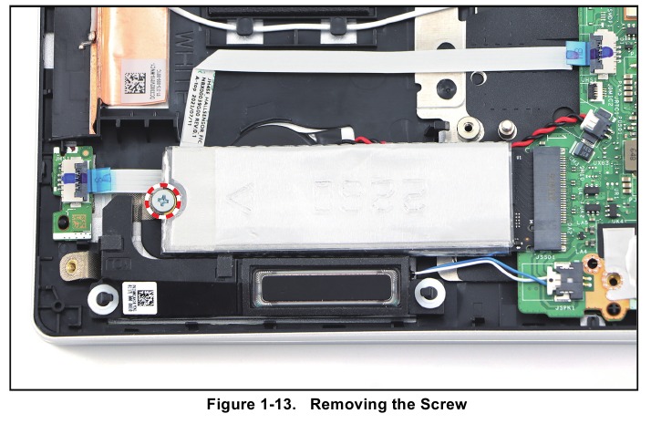
- Remove the screw securing the SSD 1 module to the upper case.
![Acer - Swift Go 14 - SSD 1 Module Removal - Step 1 SSD 1 Module Removal - Step 1]()
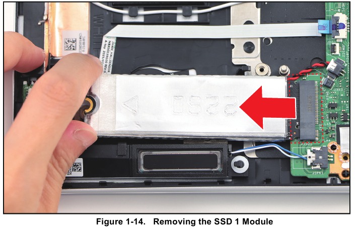
- Pull to disconnect the SSD 1 module from the mainboard connector. Then remove the SSD 1 module.
![Acer - Swift Go 14 - SSD 1 Module Removal - Step 2 SSD 1 Module Removal - Step 2]()
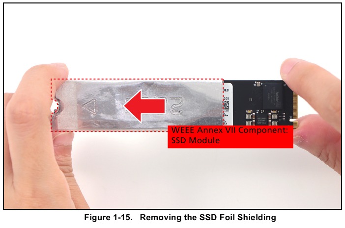
- Remove the SSD foil shielding from the SSD 1 module.
![Acer - Swift Go 14 - SSD 1 Module Removal - Step 3 SSD 1 Module Removal - Step 3]()
Table 1-4. SSD 1 Module Screw
| Screw Name | Screw Type | Torque | Quantity |
| M 2.0 x 3.0 |  | 1.8~2.2kgf.cm | 1 |
SSD 2 Module Removal
Prerequisite: Battery Removal
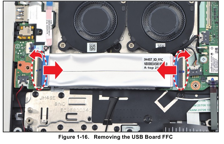
- Release the latches and disconnect the USB board FFC from the USB board and mainboard connectors. Then remove the USB board FFC.
![Acer - Swift Go 14 - SSD 2 Module Removal - Step 1 SSD 2 Module Removal - Step 1]()
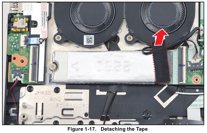
- Detach the tape securing the fan cable.
![Acer - Swift Go 14 - SSD 2 Module Removal - Step 2 SSD 2 Module Removal - Step 2]()
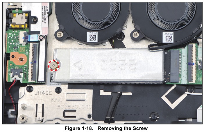
- Remove the screw securing the SSD 2 module to the upper case.
![Acer - Swift Go 14 - SSD 2 Module Removal - Step 3 SSD 2 Module Removal - Step 3]()
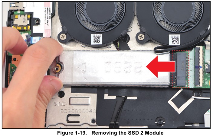
- Pull to disconnect the SSD 2 module from the mainboard connector. Then remove the SSD 2 module.
![Acer - Swift Go 14 - SSD 2 Module Removal - Step 4 SSD 2 Module Removal - Step 4]()
- Remove the SSD foil shielding from the SSD 2 module.
![Acer - Swift Go 14 - SSD 2 Module Removal - Step 5 SSD 2 Module Removal - Step 5]()
Table 1-5. SSD 2 Module Screw
| Screw Name | Screw Type | Torque | Quantity |
| M 2.0 x 2.5 |  | 1.8~2.2kgf.cm | 1 |
WLAN Module Removal
Prerequisite: Battery Removal
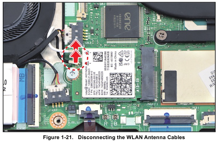
- Disconnect the WLAN antenna cables.
![Acer - Swift Go 14 - WLAN Module Removal - Step 1 WLAN Module Removal - Step 1]()
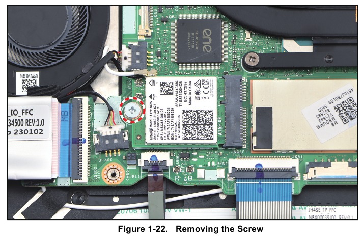
- Remove the screw securing the WLAN module to the mainboard.
![Acer - Swift Go 14 - WLAN Module Removal - Step 2 WLAN Module Removal - Step 2]()
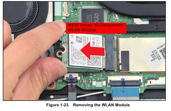
- Pull to disconnect the WLAN module from the mainboard connector. Then remove the WLAN module.
![Acer - Swift Go 14 - WLAN Module Removal - Step 3 WLAN Module Removal - Step 3]()
Table 1-6. WLAN Module Screw
| Screw Name | Screw Type | Torque | Quantity |
| M 2.0 x 2.5 |  | 1.8~2.2kgf.cm | 1 |
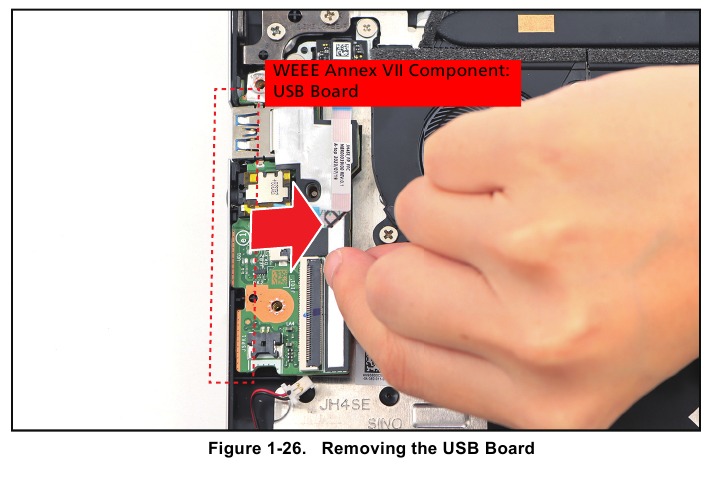
USB Board Removal
Prerequisite: Battery Removal
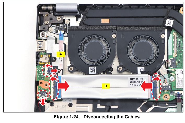
- Disconnect the right speaker cable from the USB board connector.
- Release the latch and disconnect the fingerprint FFC (A) from the USB board connector.
- Release the latches and disconnect the USB board FFC (B) from the USB board and mainboard connectors. Then remove the USB board FFC.
![Acer - Swift Go 14 - USB Board Removal - Step 1 USB Board Removal - Step 1]()
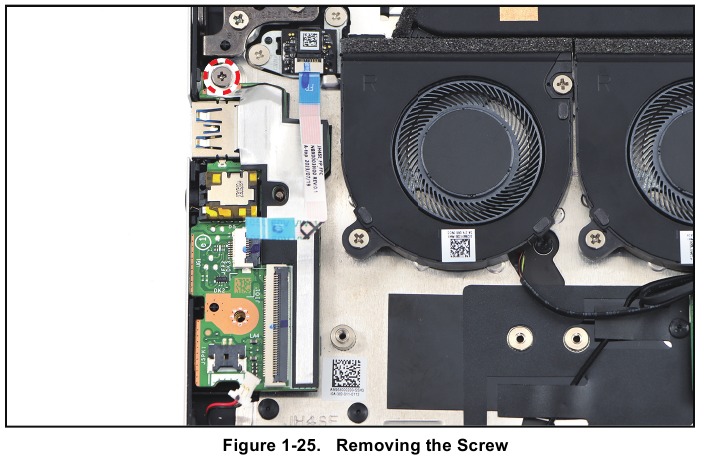
- Remove the screw securing the USB board to the upper case.
![Acer - Swift Go 14 - USB Board Removal - Step 2 USB Board Removal - Step 2]()
- Release the USB board from the I/O port slots. Then remove the USB board from the upper case.
![Acer - Swift Go 14 - USB Board Removal - Step 3 USB Board Removal - Step 3]()
Table 1-7. USB Board Screw
| Screw Name | Screw Type | Torque | Quantity |
| M 2.0 x 4.0 |  | 1.8~2.2kgf.cm | 1 |
Touchpad Removal
Prerequisite:
Battery Removal

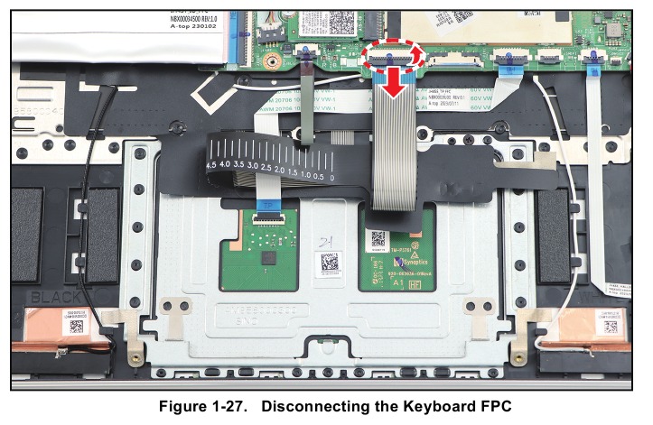
- Release the latch and disconnect the keyboard FPC from the mainboard connector.
![Acer - Swift Go 14 - Touchpad Removal - Step 1 Touchpad Removal - Step 1]()
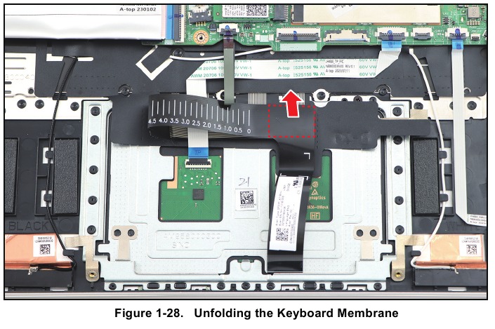
- Lift the portion of the keyboard FPC (marked with red dashed lines as shown in the below illustration) to detach it from the adhesive tape underneath.
![Acer - Swift Go 14 - Touchpad Removal - Step 2 Touchpad Removal - Step 2]()
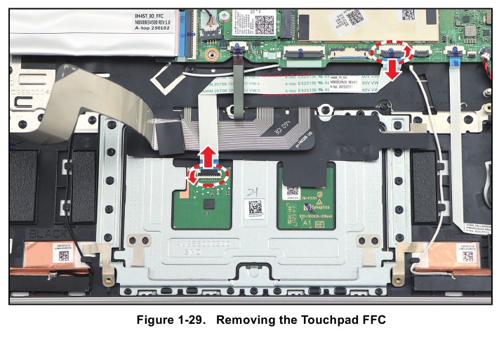
- Release the latches and disconnect the touchpad FFC from the mainboard and touchpad connectors. Then remove the touchpad FFC.
NOTE: When removing the FFC, carefully lift the portion of the touchpad FFC (marked with red dashed lines as shown in the below illustration) to detach it from the adhesive tape underneath.
![Acer - Swift Go 14 - Touchpad Removal - Step 3 Touchpad Removal - Step 3]()
- Slightly lift the keyboard mylar. Then carefully detach the conductive tape from the touchpad and upper case.
![Acer - Swift Go 14 - Touchpad Removal - Step 4 Touchpad Removal - Step 4]()
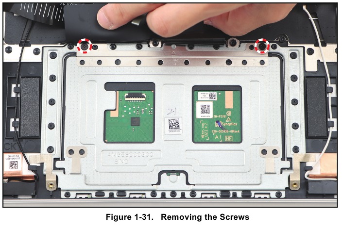
- Remove the two (2) screws securing the touchpad to the upper case.
![Acer - Swift Go 14 - Touchpad Removal - Step 5 Touchpad Removal - Step 5]()
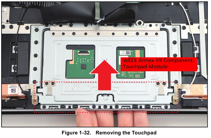
- Slide the bottom part of the touchpad forward to disengage it from the bottom tabs. Then remove the touchpad from the upper case.
![Acer - Swift Go 14 - Touchpad Removal - Step 6 Touchpad Removal - Step 6]()
Table 1-8. Touchpad Screws
| Screw Name | Screw Type | Torque | Quantity |
| M 2.0 x 2.0 |  | 1.8~2.2kgf.cm | 2 |
RTC Battery Removal
Prerequisite: SSD 1 Module Removal
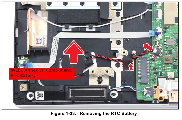
- Partially detach the mylar. Then disconnect the RTC battery cable from the mainboard connector.
- Pry to detach the adhesive tape underneath the RTC battery. Then lift the RTC battery to release it from the compartment tab. Remove the RTC battery.
![Acer - Swift Go 14 - RTC Battery Removal RTC Battery Removal]()
Mainboard Removal
Prerequisite:
- Thermal Module Removal
- SSD 1 Module Removal
- SSD 2 Module Removal
- WLAN Module Removal
- Fan 1 Module Removal
- Fan 2 Module Removal
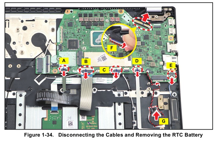
- Release the latch (if necessary) and disconnect the following cables from the mainboard connectors:
- Keyboard backlight FPC (A)
- Keyboard FPC (B)
- Touchpad FFC (C)
- Hall sensor board FFC (D)
- Left speaker cable (E)
- eDP cable (F)
- Pry to detach the adhesive tape underneath the RTC battery (G). Then partially detach the mylar and remove the RTC battery from the upper case.
![Acer - Swift Go 14 - Mainboard Removal - Step 1 Mainboard Removal - Step 1]()
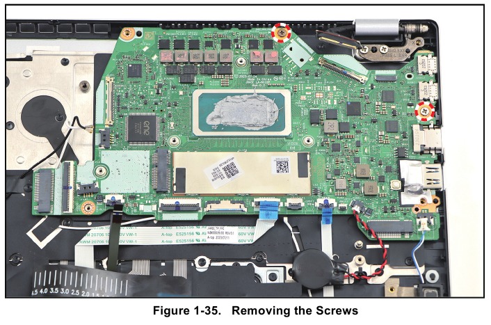
- Remove the two (2) screws securing the mainboard to the upper case.
![Acer - Swift Go 14 - Mainboard Removal - Step 2 Mainboard Removal - Step 2]()
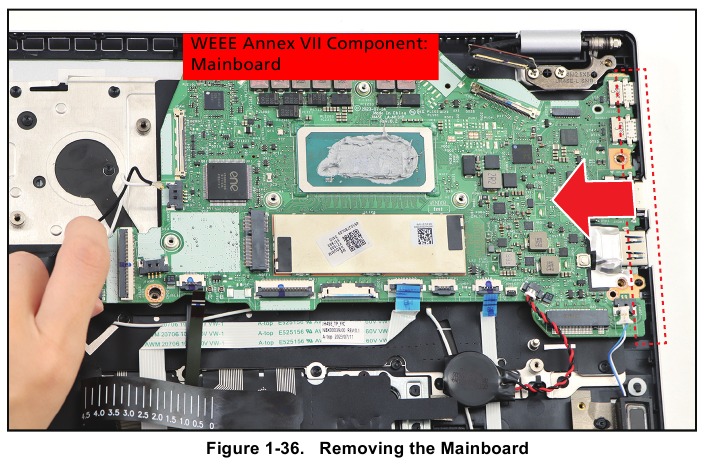
- Release the mainboard from the I/O port slots. Then remove the mainboard from the upper case.
![Acer - Swift Go 14 - Mainboard Removal - Step 3 Mainboard Removal - Step 3]()
Table 1-9. Mainboard Screws
| Screw Name | Screw Type | Torque | Quantity |
| M 2.0 x 4.0 |  | 1.8~2.2kgf.cm | 2 |
LCD Bezel Removal
Prerequisite: LCD Module Removal
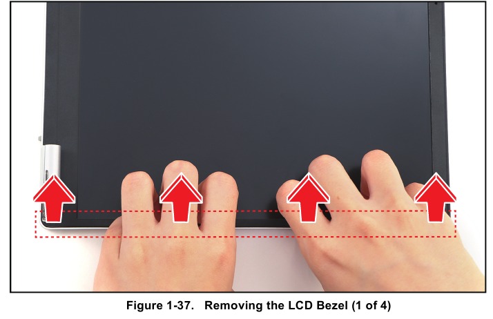
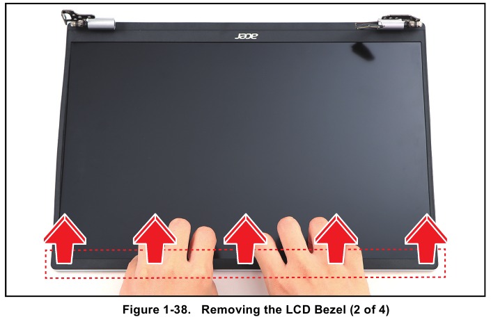
- Pry the LCD bezel from the right side to release the latches.
![Acer - Swift Go 14 - LCD Bezel Removal - Step 1 LCD Bezel Removal - Step 1]()
- Continue to release the upper side latches.
![Acer - Swift Go 14 - LCD Bezel Removal - Step 2 LCD Bezel Removal - Step 2]()
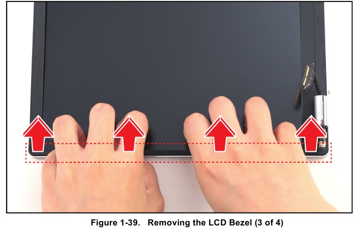
- Pry the LCD bezel from the left side to release the latches.
![Acer - Swift Go 14 - LCD Bezel Removal - Step 3 LCD Bezel Removal - Step 3]()
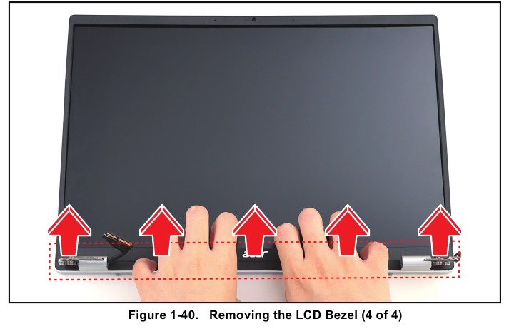
- Continue to pry the bottom side latches. Then remove the LCD bezel.
![Acer - Swift Go 14 - LCD Bezel Removal - Step 4 LCD Bezel Removal - Step 4]()
LCD Panel Removal
Prerequisite: LCD Bezel Removal
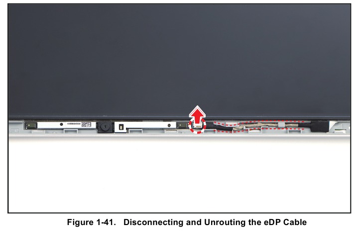
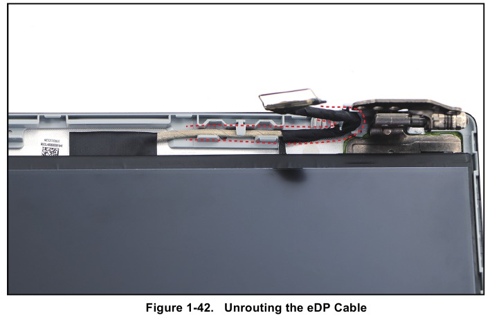
- Disconnect the eDP cable from the camera module connector. Then unroute the eDP cable from the cable guides on the upper side of the LCD cover.
![Acer - Swift Go 14 - LCD Panel Removal - Step 1 LCD Panel Removal - Step 1]()
- Unroute the eDP cable from the cable guides on the bottom side of the LCD cover and hinge as shown in the below illustration.
![Acer - Swift Go 14 - LCD Panel Removal - Step 2 LCD Panel Removal - Step 2]()
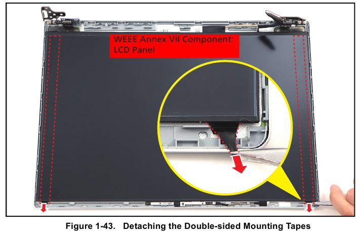
- Pry slightly to access the double-sided mounting tape underneath the LCD panel. Then carefully pull to detach the double-sided mounting tape. Repeat the same procedure to remove the double-sided mounting tape on another side of the LCD panel.
![Acer - Swift Go 14 - LCD Panel Removal - Step 3 LCD Panel Removal - Step 3]()
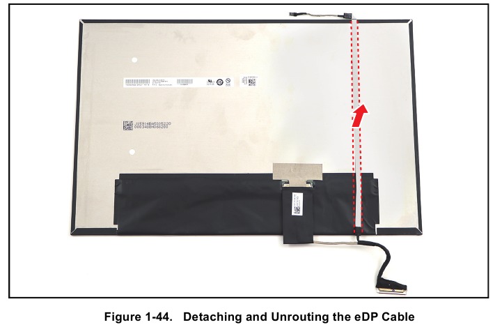
- Remove the LCD panel. Then carefully flip the LCD panel to access its connector.
- Detach and unroute the eDP cable from the LCD panel as shown in the illustration below.
NOTE: When unrouting the cable, carefully lift the portion of the eDP cable (marked with red dashed lines as shown in the below illustration) to detach it from the adhesive tape underneath.
![Acer - Swift Go 14 - LCD Panel Removal - Step 4 LCD Panel Removal - Step 4]()
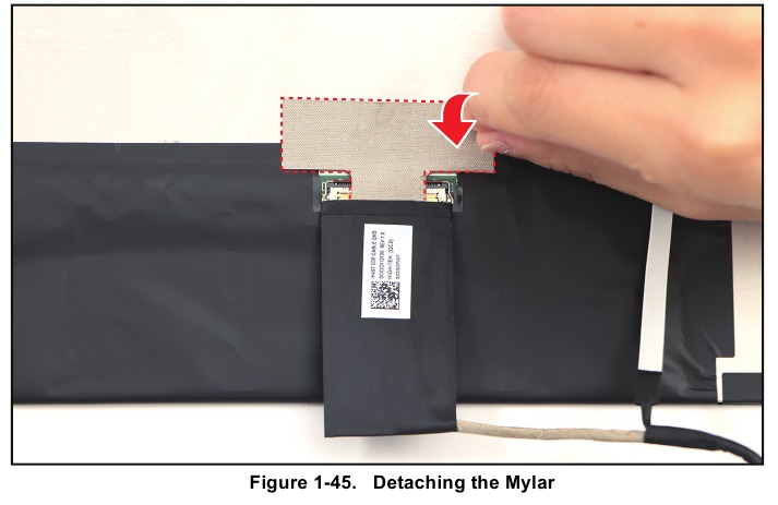
- Detach the mylar securing the eDP cable to the LCD panel connector.
![Acer - Swift Go 14 - LCD Panel Removal - Step 5 LCD Panel Removal - Step 5]()
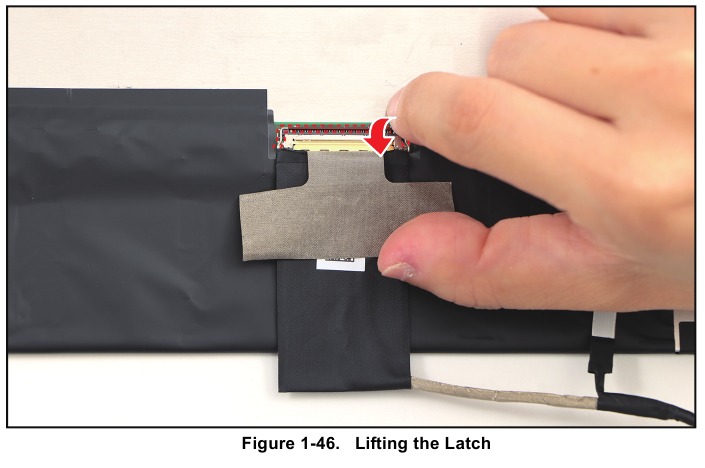
- Lift the latch securing the eDP cable.
![Acer - Swift Go 14 - LCD Panel Removal - Step 6 LCD Panel Removal - Step 6]()
- Disconnect the eDP cable from the LCD panel connector. Then remove the eDP cable.
![Acer - Swift Go 14 - LCD Panel Removal - Step 7 LCD Panel Removal - Step 7]()
Troubleshooting
This chapter shows you how to deal with common system problems. Read it before calling a technician if a problem occurs. Solutions to more serious problems require opening up the computer. Do not attempt to open the computer yourself; contact your dealer or authorized service center for assistance.
Troubleshooting tips
This computer incorporates an advanced design that delivers on-screen error message reports to help you solve problems.
If the system reports an error message or an error symptom occurs, see "Error message" below. If the problem cannot be resolved, contact your dealer.
Error messages
If you receive an error message, note the message and take the corrective action. The following table lists the error messages in the alphabetical order together with the recommended course of action.
Table 1-10. Error Messages
| Error Messages | Corrective Action |
CMOS battery bad | Contact your dealer or an authorized service center. |
CMOS checksum error | Contact your dealer or an authorized service center. |
Disk boot failure | Insert a system (bootable) disk, then press Enter to reboot. |
Equipment configuration error | Press F2 (during POST) to enter BIOS utility, then press Exit in the BIOS utility to reboot. |
Hard disk 0 error | Contact your dealer or an authorized service center. |
Hard disk 0 extended type error | Contact your dealer or an authorized service center. |
I/O parity error | Contact your dealer or an authorized service center. |
Keyboard error or no keyboard connected | Contact your dealer or an authorized service center. |
Keyboard interface error | Contact your dealer or an authorized service center. |
Memory size mismatch | Press F2 (during POST) to enter BIOS utility, then press Exit in the BIOS utility to reboot. |
If you still encounter problems after going through the corrective measures, please contact your dealer or an authorized service center for assistance.
FRU (Field Replaceable Unit) List
Please contact your local service center to find out how to obtain the part or replace your device.
Exploded Diagrams
Main Assembly
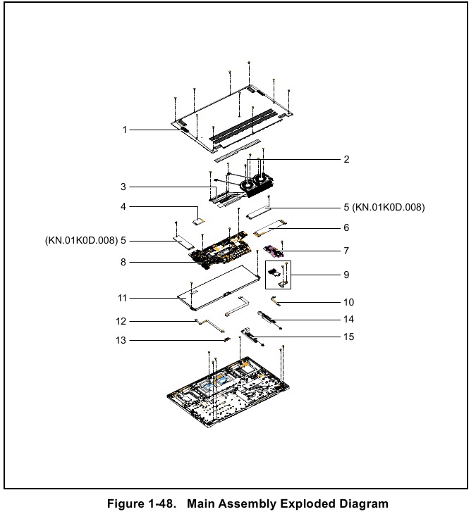
Table 1-11. Main Assembly Exploded Diagram
| No. | Description | P/N |
| 1 | LOWER CASE | 64.KRKN2.001 |
| 2 | FAN | 23.KF2N2.001 |
| 3 | THERMAL MODULE | 24.KRKN2.001 |
| 4 | WLAN MODULE | KE.WF60N.003 |
| 5 | SSD MODULES | KN.01K0D.008 |
| 6 | USB BOARD FFC | 50.KRKN2.001 |
| 7 | USB BOARD | 55.KRKN2.001 |
| 8 | MAINBOARD | NB.KPE11.001 |
| 9 | FINGERPRINT BRACKET | 33.KRKN2.001 |
| FINGERPRINT MODULE | NC.22011.01Y | |
| 10 | FINGERPRINT FFC | 50.KRKN2.004 |
| 11 | BATTERY | KT.0030G.020 |
| 12 | HALL SENSOR BOARD FFC | 50.KRKN2.002 |
| 13 | HALL SENSOR BOARD | 55.KRKN2.002 |
| 14 | RIGHT SPEAKER | 23.KRKN2.002 |
| 15 | LEFT SPEAKER | 23.KRKN2.001 |
Upper Case Assembly
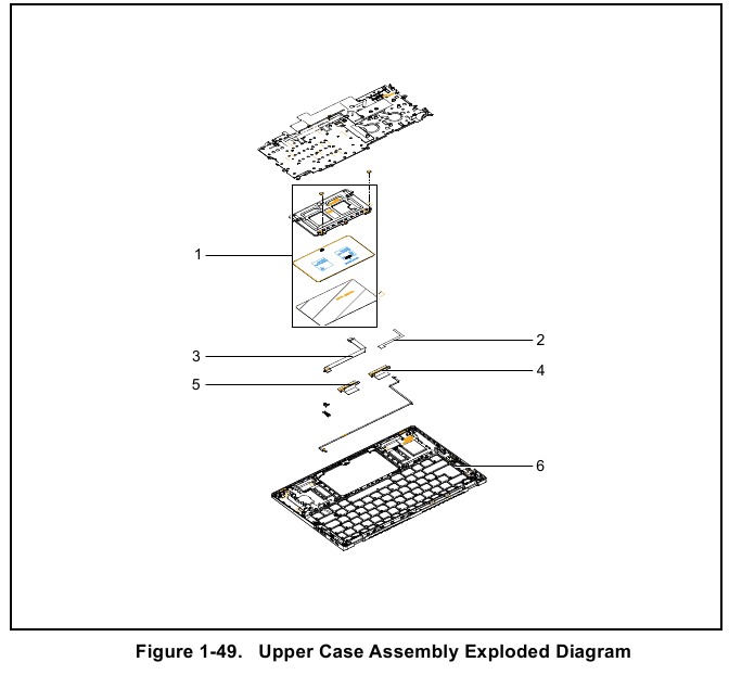
Table 1-12. Upper Case Assembly Exploded Diagram
| No. | Description | P/N |
| 1 | TOUCHPAD | 56.KRKN2.001 |
| 2 | CONDUCTIVE TAPE | 47.KRKN2.001 |
| 3 | TOUCHPAD FFC | 50.KRKN2.003 |
| 4 | MAIN ANTENNA | 50.KRKN2.005 |
| 5 | AUX ANTENNA | 50.KRKN2.006 |
| 6 | UPPER CASE | 6B.KRKN2.001 |
LCD Assembly
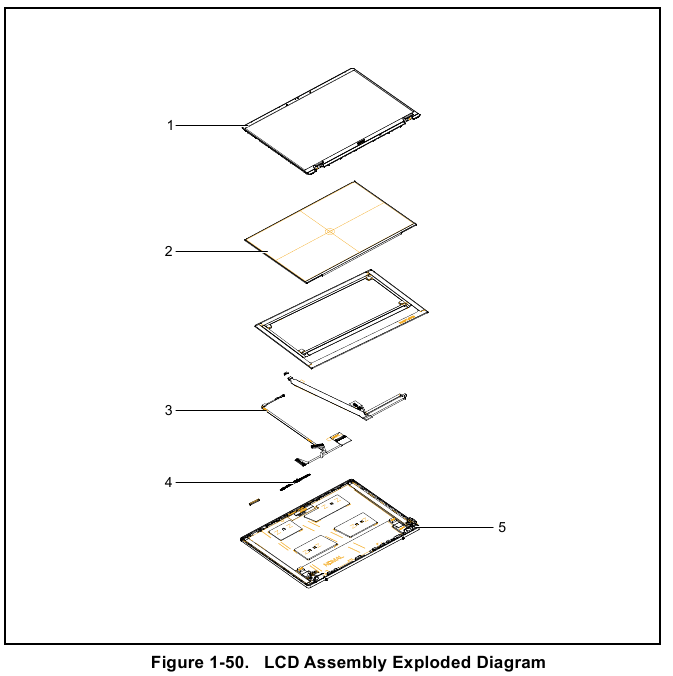
Table 1-13. LCD Assembly Exploded Diagram
| No. | Description | P/N |
| 1 | LCD BEZEL | 60.KF2N2.003 |
| 2 | LCD PANEL | 6M.KF1N2.001 |
| 3 | EDP CABLE | 50.KF2N2.008 |
| 4 | CAMERA | KS.QHD06.006 |
| 5 | LCD COVER | 61.KRKN2.001 |
Software Update
Please visit http://go.acer.com/?id=17883.
Personal Data Removal
There are three options to choose from:
- Option 1: Select Start
![]() > Settings
> Settings ![]() > Update & Security
> Update & Security ![]() > Recovery. Under Reset this PC, select Get started. Open Recovery settings.
> Recovery. Under Reset this PC, select Get started. Open Recovery settings. - Option 2: Restart your PC to get to the sign-in screen, then press and hold down the Shift key while you select the Power
![]() icon > Restart in the lower-right corner of the screen. After your computer restarts, select Troubleshoot > Reset this PC.
icon > Restart in the lower-right corner of the screen. After your computer restarts, select Troubleshoot > Reset this PC. - Option 3: Select Start
![]() , then press and hold down the Shift key while you select the Power
, then press and hold down the Shift key while you select the Power ![]() icon > Restart to restart your computer into Recovery Mode. After your computer restarts, select Troubleshoot > Reset this PC.
icon > Restart to restart your computer into Recovery Mode. After your computer restarts, select Troubleshoot > Reset this PC.
Documents / Resources
References
Download manual
Here you can download full pdf version of manual, it may contain additional safety instructions, warranty information, FCC rules, etc.
Advertisement
 button
  > Update & Security
  > Windows Update


 icon > Restart in the lower-right corner of the screen. After your computer restarts, select Troubleshoot > Reset this PC.


Need help?
Do you have a question about the Swift Go 14 and is the answer not in the manual?
Questions and answers