Advertisement
Safety information

Failure to follow instructions and standard safety procedures can result in death, personal injury or substantial property damage.
Only a qualified electrician must be allowed to perform the electrical installation tasks.
National and local electrical safety regulations must always be followed.
NOTICE
Notice is used to address practices not related to physical injury
Installation instructions
The following information is provided for your reference during the installation of PSTX soft starter normal and heavy duty panels. Please note that all equipment must be installed in accordance with the applicable NFPA 70 (National Electrical Code, NEC) edition and local building codes (or similar). PSTX soft starter normal, heavy and extreme duty panels are built to the UL 508A industrial control panel standard. This document provides information pertaining to: inspections, environment, installation and wiring. The PSTX user's manual (1SFC132082M9901) and the PSTX soft starter panel operating instructions contained in this document offer additional information and will be referenced throughout
Initial inspection
After unpacking your soft starter panel, inspect it for damage that may have occurred during shipment.
If any damage is found, please report it to the distributor from which the panel was purchased.
NOTICE
Care should be taken when unpacking the panel; improper use of tools could damage equipment.
Preparing for installation
Remove and discard desiccant/drying/silica packs if included.
Before you begin to install the PSTX soft starter panel, make sure the proper equipment for lifting is available. Refer to the appropriate outline drawing for the dimensions, estimated weight and required clearances for installation. Refer to the rating label on back of the cover to verify that the received product matches the ordered unit and verify the product listing/marking label.
Improper lifting of enclosure could result in a fatal or serious injury.
Review the layout and elementary diagrams before starting to wire your soft starter panel. Care should be taken when unpacking the panel; improper use of tools could damage equipment.
NOTICE
Enclosure panel doors can swing more than 90 degrees, and there are no stops to inhibit the door from hitting equipment located next to the panel. This could result in damage to door-mounted switches and indicator lights.
Environment
PSTX soft starter normal and heavy duty panels are available in enclosures rated NEMA Type 1, 12 3R and 4. The environment must be totally free from flammable or combustible vapors and/ or dust. The environments for NEMA Type 1 enclosures shall be indoors where the following condition may exist: falling dirt. The environments for NEMA Type 12 enclosures shall be indoors where the following conditions may exist: falling dirt, circulating dust and/or non-corrosive dripping liquids. The environments for NEMA Type 3R enclosures shall be indoors or outdoors where the following conditions may exist: falling dirt, rain, sleet, snow and external formation of ice on the enclosure.
The environments for NEMA Type 4 enclosures shall be indoors or outdoors to provide a degree of protection to personnel against access to hazardous parts; to provide a degree of protection against ingress of solid foreign objects (falling dirt and windblown dust); to provide a degree of protection with respect to harmful effects on the equipment due to the ingress of water (rain, sleet, snow, splashing water and hose-directed water); and that will be undamaged by the external formation of ice on the enclosure.

Failure to comply with the following instruction could result in a fire and/or explosion, resulting in a fatal or serious injury.
For all enclosure types, the ambient temperature must remain in the range of -10°C to 40°C (14°F to 104°F). Never store or operate the panel below or above the ambient range.
Use the formula below to derate panels for ambient temperatures above 40°C and altitude above 4000 meters.
When used at high altitudes, de-rate the rated current using the following formula:
1000 m (3281 ft.) above sea level without derating. 1000–4000 m (3281–13,123 ft.) with derating 0.7%/100 m (0.22%/100 ft.)
NOTICE
Notice damage to equipment will result if panel is operated or stored below or above stated ambient temperature range.
All wall-mounted enclosures must be mounted on a non-flammable or heat-resistant surface.
The temperature of the starter heat sink fins may reach 90°C (194°F). Thus, if not mounted on a heat-resistant or non-flammable surface, a fire may occur, resulting in a fatal or serious injury, as well as damage to equipment.
Do not mount the enclosure in direct sunlight. This applies to ALL enclosure types.
Some PSTX soft starter panel configurations require enclosure ventilation to keep the components and starter unit within their thermal recommendations. The enclosure door and sides contain grilles at the bottom and top to allow for air circulation through the enclosure. Ventilation is accomplished by the cooling fan(s) mounted at the bottom grille(s) pulling air into the enclosure and forcing it out the top grille(s).
The air used for ventilating the enclosure must be free from condensation, moisture, dirt, dust and flammable or combustible vapors and/or dust.
The recirculation of air leaving the enclosure should be avoided. Air forced out of the enclosure should not be allowed to circulate back into the enclosure. All enclosures should be installed where the doors are able to open completely. Do not mount the enclosure where air flow into or out of it may be restricted.
Installation
Determine conduit entry and exit locations on the enclosure before mounting. See the appropriate outline drawing for recommended conduit locations.
Allow for input and output power wiring to be located in separate conduit.
No conduit holes are provided in the enclosure except for knockouts in some enclosures; therefore, the customer must install all conduit holes. Place a protective covering over the components of the panel while installing the conduit holes to prevent metal shavings or chips from landing on components or electronic boards.
NOTICE
Failure to cover components to protect them from metal shavings may result in damage to equipment.
For NEMA 12, 3R and 4 enclosure types, liquid-tight conduit (UL listed rain-tight conduit hubs) and fittings must be installed to maintain the enclosure integrity.
Grounding
All panels/enclosures must be grounded.
Each panel contains a grounding lug with provisions for connecting a field-grounding conductor.
All field wiring shall be copper and have a minimum insulation rating of 75°C (167°F).
Size grounding conductors according to local and national codes.
Grounding methods must comply with local and national codes.
Power wire
(greater than 120 V AC) A
ll field wiring shall be copper and have a minimum insulation rating of 75°C (167°F).
Size all wire based on panel nameplate current ratings in accordance with local and national codes.
All power wiring must be routed away from other control wiring. Avoid running power wiring parallel to other wiring without a minimum separation distance of four (4) inches. Power wiring should only cross perpendicular to other wiring.
Input and output power must be connected as per the wiring diagram.
NOTICE
Do not connect power supply voltage greater than panel rated voltage, or damage will occur to equipment.
Refer to electrical schematic and labels (inside cover) for torque values for customer input and output power connections.
Never connect or disconnect input wiring with voltage applied. A serious or fatal injury may result.
Never connect or disconnect output wiring with voltage applied. A serious or fatal injury may result.
Control wiring
(120 V AC)
All field wiring shall have a minimum insulation rating of 75°C (167°F).
Size wire according to local and national codes. The enclosed soft starter panel comes with 120 V AC control supply, which is supplied by the CPT from the factory. The PSTX also has a built-in 24 V DC power supply.
All control wiring must be routed away from power wiring. If control wiring is routed parallel to signal wiring (24 V DC or less), isolation of the signal wiring must be maintained. A minimum of four (4) inches is required to adequately separate signal and control wiring. If signal wire is UL recognized shielded cable, separation can be minimized to a one (1) inch separation.
Signal wiring
(24 V DC or less)
All field wiring shall have a minimum insulation rating of 75°C (167°F).
Size wire according to local and national codes.
All field signal wiring must be twisted and shielded. All shields must be grounded at one point ONLY. It is recommended to terminate the shield drains at the signal's source. Avoid routing signal wiring with power wiring. If signal wiring is routed with control wiring, a minimum separation of one (1) inch is required.
If your application requires wiring to the PSTX soft starter control terminals, use 16 to 18 AWG wire. Refer to the PSTX manual for more details.
Connections to the soft starter terminals should be tight enough so that a slight tug on the wire will not result in the wire coming partially or completely out of the terminal board.
NOTICE
Do not over-tighten terminals and connectors. Damage to the equipment may occur.
Miscellaneous information
If your enclosure is equipped with forced ventilation for keeping the starter and other components within their thermal recommendations, the cooling fan(s) used to ventilate your enclosure need to be cleaned periodically. Cleaning the cooling fan(s) is recommended to keep the proper amount of air circulating through the enclosure. The PSTX soft starters have fans for ventilation internal to the PSTX device.
ABB recommends that all power connections be checked for proper tightness every 6 months due to thermal cycling that may occur during normal operation.
Inspection #2
Prior to start-up of your PSTX soft starter panel, inspect the following:
- The mechanical installation for any safety issues and any violation of local or national code.
- The electrical installation for proper connections and any violation of local or national code.
- Proper grounding of equipment.
- All field wiring for tight and proper connections (no split wire ends that may come into contact with adjacent connection points).
- No loose hardware, metal shavings or wiring chips.
- All factory wiring for proper tightness that may have become loose due to shipping vibration.
Operating instructions
Your solid-state normal or heavy duty panel comes with a PSTX soft starter from ABB mounted in an enclosure and may contain the following equipment for soft starter control of the motor and, if included, the ability to manually or automatically allow motor operation across-the-line.
- ABB non-fused disconnect with through-the-door lockable handle (optional) (or equivalent)
- ABB fused disconnect with through-the-door lockable handle (optional) (or equivalent)
- ABB Tmax XT thermal circuit breaker with through-the-door lockable handle
- ABB AF series 3-pole non-reversing contactors
- ABB EF series electronic motor overload relays
- ABB A3TM selector switches
- ABB A3TM indicating lights
- ABB A3TM push buttons
- ABB NFTM series control relays
- ABB Type IP encapsulated or vacuum impregnated 115 V AC control power transformer with fuses
- Mersen or Bussmann time-delay class J fuses (or equivalent)
- Optional ABB terminal blocks
These instructions are intended as a supplement to the user's guide for the PSTX soft starter. For programming, operating and troubleshooting instructions for the soft starter, please refer to the user's guide, which is included with your XD and ND panel documentation package.
Read more: PSTX soft starter user manual, 1SFC132082M9901.
Also included with your XD or ND panel documentation package are installation instructions and electrical and mechanical drawings of your XD or ND panel. Drawings can also be downloaded from the ABB website.
See "Product electrical and mechanical drawings" for website link.
Operator devices
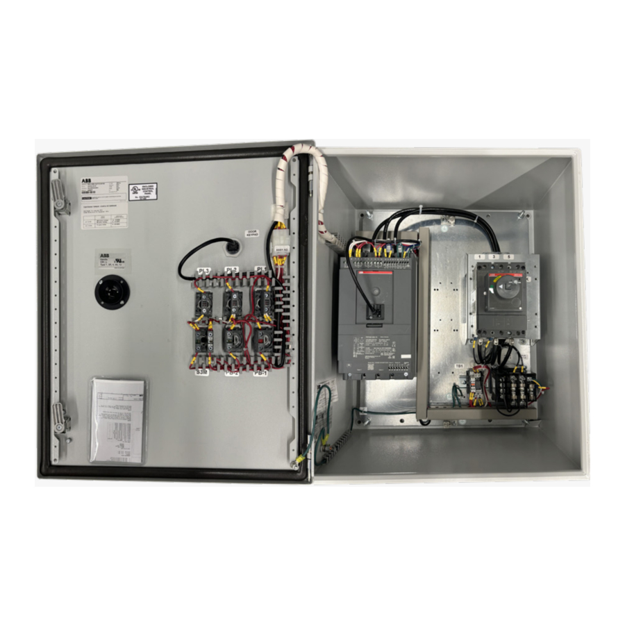
PSTX soft starter panel
Below is the typical inside layout of a PSTX soft starter panel.


- Pilot device layout, normal duty and heavy duty (ND): enclosure cover
- Pilot device layout, extreme duty (XD): enclosure cover
Your PSTX soft starter panel is equipped with several panel door-mounted operator devices, which may include the following:
- ND — one (1) through-the-door, lockable, input device disconnect handle; one (1) operator selector switch; two (2) pushbuttons; one (1) door-mounted keypad and three (3) indicator lights.
- XD — one (1) through-the-door, lockable, input device disconnect handle; two (2) operator selector switches; four (4) pushbuttons; one (1) door-mounted keypad and four (4) indicator lights.
Based on the selection, these components may or may not be present in the panel. The operation of these devices is explained in this section. Refer to the soft starter terminal board I/O section of this manual and wiring diagrams for specifics on wiring connections.
Input disconnect
The purpose of the panel-mounted input disconnects with through-the-door handle is to provide a local, lockable method of removing all AC input power from the normal or heavy duty panel and PSTX soft starter.
Even when the disconnect or breaker handle is in the "OFF" position, this does not guarantee that dangerous voltage levels are absent at the line side of the disconnect or breaker. Always make sure to disconnect the upstream breaker or disconnect to remove power to the panel before working on it.
If your panel includes a circuit breaker, in addition to providing a manual method of applying and removing AC input power from the normal and heavy duty panel, the circuit breaker also provides short circuit protection for the panel components and the motor.
Improper setting of the circuit breaker trip level can result in code violations or inadequate short circuit protection, possibly resulting in a fire or safety hazard. Refer to the "Adjustments" section of this manual for further instructions on setting the circuit breaker trip level.
Device terminal board I/O
Any of the PSTX soft starter terminal board I/O points, other than those already in use for proper operation of the solid-state PSTX panel, are available for customer use. The meanings and connection diagrams for these I/O points are well described and illustrated in the PSTX soft starter user's guide (1SFC132082M9901), which is supplied with your panel documentation package. However, several I/O points that will find frequent use in BYPASS and NON-BYPASS panel applications are described below for convenience. Refer to the 1SFC132082M9901 PSTX user's guide for terminal locations. Refer to the wiring diagram for details on correct connection points.

| Terminals | Purpose |
| 1L1, 3L2, 5L3 | Connection to mains voltage up to 690 V |
| 2T1, 4T2, 6T3 | Connection to motor |
| GND | Connection to ground |
| L (1) | Control power phase (120 V AC from supplied CPT) |
| N (2) | Control neutral (return) (120 V AC from supplied CPT) |
| 4, 5, 6 | Programmable output relay terminals (K4 is used for the RUN pilot light) |
| 7, 8, 9 | Programmable output relay terminals (K5 is not used) |
| 10, 11, 12 | Programmable output relay terminals (K6 is used for the FAULT pilot light) |
| 13, 14 | Start and stop terminals |
| 15, 16, 17 | Programmable input terminals |
| 18, 19, | Start and stop terminals |
| 20, 21 | Start and stop terminals |
| 22 | Connect the functional ground to a ground point close to the soft starter |
| 23, 24 | Modbus ext. I/O |
| T1, T2, T3 (25, 26, 27) | Thermistor input is programmable as a PTC type thermistor, PT100 |
| 28, 29, 30 | +24 V, +analog out and GND |
| AJ45 | RS 485 communication (built into PSTX unit); the RJ45 connection is a cable connection to the HMI keypad mounted to the front of the enclosure |
Note: 120 V A C connected to any digital terminals from 13 through 17 will damage the control board.
Adjustments
The solid-state PSTX panel offers several usersettable adjustments, which allow it to be tailored specifically for your three-phase induction motor. Setting these adjustments appropriately is an important factor in ensuring that applicable safety codes are met and that your panel, wiring and motor are adequately protected. The following list comprises all of the user-adjustable devices/ components inside the solid-state PSTX panel. The user may wish to have a copy of NFPA 70 (commonly known as the National Electrical Code, or simply NEC) available for reference when setting these adjustments.
Input fuses
In general, there are two configurations that use input fuses:
- input disconnect with load side separately mounted fuses; and
- input fused disconnect where fuses are an integral part of the disconnect.
If your panel was ordered with the circuit breaker option, the disconnect device and fuses are replaced by the circuit breaker. For fused disconnect panels, the main input fuses provided with your panel have been closely coordinated to provide short circuit protection for the starter along with short circuit and overcurrent protection for the motor. In "soft starter" mode of operation, the fuses only provide short circuit protection due to the fact that the starter has inherent overcurrent protection. In "bypass" mode of operation, the fuses provide both short circuit and overcurrent protection for the motor.
Power fuses are not supplied with the enclosed panels. UL listed Class J time-delay fuses are recommended for disconnect panels. These fuses should be sized in accordance with NEC section 430-52. The NEC states fuses of this type are to be sized at 175% of motor full-load amps (FLA). Due to the fact that actual motor FLA along with starting current requirements vary among manufacturer and motor types, the fuses provided are based on standard NEC motor data. Verify that the input fuse amp rating is less than or equal to the actual motor FLA x 1.75. In a case where the actual motor FLA x 1.75 is less than the provided fuses' amp rating, then smaller fuses may need to be installed to comply with NEC section 430-52. Please review NEC section 430.52(c)1(a), which states that where the calculated fuse amp rating does not correspond to a standard fuse size, the next higher standard fuse size may be used. In cases where the fuses provided are not sufficient for the starting current requirements of the motor, please review 430.52(c)1(b), which states that rating of a time-delay fuse may be increased but shall not exceed 225% of the motor FLA in any case. In the case where a larger or smaller fuse is required, the fuse holder in the panel may be a limiting factor.
Coordinating the fuses for the solid-state PSTX panel is the overcurrent protection coordination between the Class 10/20/30 overload relay and the fuse's overcurrent protection. This coordination is to avoid nuisance blowing of fuses. Coordination between the soft starter short circuit rating and the fuse's RMS let-through currents during a short circuit condition has also been closely evaluated. Changing the main input fuses may impact one or both of the above coordination issues. Therefore, if it is necessary to change the input fuses, refer to UL short circuit document 1SFC132423M0201.
Circuit breaker trip level
The optional circuit breaker in the solid-state PSTX is a solid-state Tmax® XT series molded case circuit breaker from ABB. The purpose of the circuit breaker is to provide short circuit protection and overcurrent protection for the panel components, field wiring and motor. The breaker uses a solidstate sensing element, which calculates the true rms value of the current every cycle, resulting in very fast tripping action. For this reason, the NEC allows the trip level to be set at 700% of the motor FLA to allow for the high locked rotor current, which the motor draws during across-the-line starts (see NEC section 430-52). Because instantaneous trip circuit breakers are so fast acting, the NEC actually allows trip level settings up to 1300% of motor FLA if it can be shown to be required by engineering evaluation. A motor started across the AC line can draw a very large peak current for the first halfcycle, which can result in nuisance tripping in instantaneous trip breakers set at 700%. The ABB Motors and Electrification businesses have conducted analyses that show that certain models can require this 1300% trip level to avoid nuisance tripping on across-the-line starts. Generally, trip level will need to be higher for premium-efficiency motors than for standard-efficiency ones.
The adjustable breakers are set to minimum settings from the factory and must be set appropriately in the field by the installer.
The ratings for the circuit breakers in solid-state PSTX panels have been chosen to allow trip level settings up to 13 times the current ratings of the panel. If the trip level is set at 13 times the motor FLA and the circuit breaker still trips, it is probably due to the fact that your motor has very high efficiency and, therefore, exhibits the highest inrush currents. Refer to "Product electrical and mechanical drawings" chapter of this document section for troubleshooting assistance
Motor overload trip level
The overload relay in your solid-state PSTX panel is an EF series electronic overload relay, Class 10, 20 or 30 type from ABB, and is panel/starter mounted. The overload relay carries all motor current when it is running in BYPASS mode. Whereas the panel circuit breaker or input fuses are intended to provide short circuit protection for the panel components, field wiring and motor, the overload relay's function is to provide continuous long-term overload protection against loads that draw current in excess of the motor's rating.
Refer to 1SBC100214C0202 for technical data on contactors and overload relays.
The trip level dial on the contactors should be set as follows.
- Motors with service factor of 1.15 or greater — Adjust OL relay dial to the motor nameplate FLA.
- Motors with service factor less than 1.15 — Adjust OL relay dial according to this formula: FLA x service factor x 0.90
Example: 30 A motor with 1.00 service factor
Set OL dial at 30 x 0.90 = 27.0 A
The overload relay dial should never be set higher than the panel's rated current even if allowed by the above formula.
NOTICE
For all PSTX normal and heavy duty panels, the overload relay dial should never be set higher than the panel's rated current even if allowed by the above formula, because the overload relay protects panel components such as the contactors in addition to the motor
If the overload relay dial is set correctly but trips in normal running situations, your motor is probably undersized for your load. Possible corrective actions are:
- Make sure there is no unintended additional loading on the motor resulting in excessive current.
- Try another overload relay. Possibly, the tolerances on the one included with your panel are unfavorable.
If the overload relay dial is set correctly but tripping occurs on across-the-line starts, it is probably due to a large load inertia that results in high starting current being applied for a longer time to accelerate the motor from a stopped to full speed condition. Traditionally, the problem of starting motors with high inertia loads across the line has been solved by a number of methods falling into the category of soft starters. The PSTX soft starter is a "soft starter" because it applies a very low voltage to the motor when it is stopped and gradually increases to full voltage at full speed. Recognizing that this problem can only occur during full voltage across-the-line starts (in other words, starting in bypass mode), refer to "Product electrical and mechanical drawings" chapter of this document section for troubleshooting assistance.
The overload relay should not be turned to a higher setting than allowed by the rules above to allow starting the motor across the line without tripping. Doing so will compromise the overload protection, which could lead to component damage or fire that could threaten personnel safety. Refer to the NEC for further information.
Tripping curves for electronic overload protection
Tripping curves for the integrated electronic overload protection. All units have an integrated electronic overload protection that can be set to four different tripping classes. Below you will find a curve for each tripping class in cold state. These tripping curves are valid for PSTX.

Unit function code changes
The PSTX soft starter has programmable functions. A complete description of these function codes can be found in the 1SFC132082M9901 PSTX user's guide. The PSTX unit will come with factory default settings.
Troubleshooting
Motor rotation in soft starter and bypass mode
If careful attention to phase rotation is not paid during connection of the panel to the three-phase power supply and motor, only a one in four chance exists that the motor will rotate correctly in both soft starter and bypass modes.
The other three possibilities and the corresponding corrective actions are as follows:
- Problem: Motor turns correctly in bypass mode and incorrectly in soft starter mode.
- Solution: Swap two of three line power leads connected to the PSTX's load side power terminals (i.e., 2T1, 4T2, 6T3). Do not change any other wiring.
- Problem: Motor turns correctly in soft starter mode and incorrectly in bypass mode.
- Solution: Swap two of three line power leads.
- Problem: Motor turns incorrectly in both modes.
- Solution: Swap two of three motor leads.
Note that if the rotation in bypass mode is opposite to the rotation in soft starter mode, it is possible that the panel's motor overload will trip if a fullspeed transition between modes is attempted. This is due to the large amount of current required to decelerate the motor to a stop prior to accelerating it in the correct direction.
Circuit breaker trip level
Possible corrective actions are:
- Check the trip setting in the breaker rating.
- Make sure an actual short is not causing the trip.
- Try closing the breaker several times. Actual inrush is dependent on line conditions when the breaker is closed. Closing the breaker when line conditions are acceptable should prevent tripping.
- Since actual inrush is dependent on the line conditions, correct the line condition that is causing excessive inrush.
- Try another breaker rating. Perhaps the tolerances on the one included with your breaker are unfavorable.
- Start the motor in soft starter mode.
- For NEMA E motors (super premium efficiency), the NEC 2023 version will allow a trip setting of 1700% of motor FLA.
Motor overload trip level
Possible corrective actions are:
- Allow the overload to cool sufficiently between restarts. There is typically a 4 to 1 difference between the operation time of the overloads in their cold state versus their warm state.
- Try another overload relay of the same rating. Tolerances on the overloads are loose, and trip times can vary significantly from unit to unit of the same rating (range of 2 to 1 or more is not uncommon).
- Reduce the load on the motor during acceleration. Total motor load during this period is the sum of the accelerating torque plus load torque. Once the motor is up to speed, the load can be reapplied.
Soft starter fault codes
Refer to the 1SFC132082M9901 PSTX user manual for troubleshooting assistance.
Refer to electric schematic and outline drawings, which are included with the unit, for wiring and mounting details. You can also download these documents from the ABB website.
PSTX installation and commissioning manual, 1SFC132081M0201.
Contact the ABB team by phone or email:
888-385-1221 ext. 1 eppc.support@us.abb.com
Product electrical and mechanical drawings
Please use the following links for electrical schematic and mechanical layout drawings available in the ABB library.
| Order code | Type | Mechanical drawing | Electrical drawing |
| 3AUA0000224500 | X20-B4-48-ND | M-SST-300050 | E-SST-300044 |
| 3AUA0000224501 | X50-B4-48-ND | M-SST-300050 | E-SST-300044 |
| 3AUA0000224502 | X75-B4-48-ND | M-SST-300050 | E-SST-300044 |
| 3AUA0000224503 | X100-B4-48-ND | M-SST-300062 | E-SST-300044 |
| 3AUA0000224504 | X125-B4-48-ND | M-SST-300062 | E-SST-300044 |
| 3AUA0000224505 | X150-B4-48-ND | M-SST-300073 | E-SST-300044 |
| 3AUA0000224506 | X200-B4-48-ND | M-SST-300073 | E-SST-300044 |
| 3AUA0000224507 | X250-B4-48-ND | M-SST-300074 | E-SST-300044 |
| 3AUA0000224508 | X300-B4-48-ND | M-SST-300074 | E-SST-300044 |
| 3AUA0000224509 | X400-B4-48-ND | M-SST-300078 | E-SST-300044 |
| 3AUA0000224510 | X500-B4-48-ND | M-SST-300079 | E-SST-300044 |
| 3AUA0000224511 | X600-B4-48-ND | M-SST-300108 | E-SST-300044 |
| 3AUA0000224512 | X700-B4-48-ND | M-SST-300093 | E-SST-300044 |
| 3AUA0000226360 | X50-B4-48-XD | M-SST-300051 | E-SST-300043 |
| 3AUA0000226361 | X75-B4-48-XD | M-SST-300063 | E-SST-300043 |
| 3AUA0000226362 | X100-B4-48-XD | M-SST-300063 | E-SST-300043 |
| 3AUA0000226363 | X125-B4-48-XD | M-SST-300075 | E-SST-300043 |
| 3AUA0000226364 | X150-B4-48-XD | M-SST-300075 | E-SST-300043 |
| 3AUA0000226365 | X200-B4-48-XD | M-SST-300076 | E-SST-300043 |
| 3AUA0000226366 | X250-B4-48-XD | M-SST-300076 | E-SST-300043 |
| 3AUA0000226367 | X300-B4-48-XD | M-SST-300086 | E-SST-300043 |
| 3AUA0000226368 | X400-B4-48-XD | M-SST-300091 | E-SST-300043 |
| 3AUA0000226369 | X500-B4-48-XD | M-SST-300092 | E-SST-300043 |
| 3AUA0000228980 | X600-B4-48-XD | M-SST-300104 | E-SST-300043 |
| 1SQA013218R0001 | X25-F4-60-ND | M-SST-300052 | E-SST-300046 |
| 1SQA013219R0001 | X50-F4-60-ND | M-SST-300053 | E-SST-300046 |
| 1SQA013220R0001 | X60-F4-60-ND | M-SST-300053 | E-SST-300046 |
| 1SQA013221R0001 | X75-F4-60-ND | M-SST-300054 | E-SST-300046 |
| 1SQA013225R0001 | X100-F4-60-ND | M-SST-300054 | E-SST-300046 |
| 1SQA013222R0001 | X125-F4-60-ND | M-SST-300064 | E-SST-300046 |
| 1SQA013226R0001 | X150-F4-60-ND | M-SST-300065 | E-SST-300046 |
| 1SQA013227R0001 | X200-F4-60-ND | M-SST-300080 | E-SST-300046 |
| 1SQA013223R0001 | X250-F4-60-ND | M-SST-300080 | E-SST-300046 |
| 1SQA013228R0001 | X300-F4-60-ND | M-SST-300081 | E-SST-300046 |
| 1SQA013224R0001 | X350-F4-60-ND | M-SST-300081 | E-SST-300046 |
| 1SQA013229R0001 | X500-F4-60-ND | M-SST-300082 | E-SST-300046 |
| 1SQA013230R0001 | X600-F4-60-ND | M-SST-300112 | E-SST-300046 |
| 1SQA013231R0001 | X700-F4-60-ND | M-SST-300095 | E-SST-300046 |
| 1SQA013232R0001 | X800-F4-60-ND | M-SST-300095 | E-SST-300046 |
ABB Inc.
305 Gregson Dr.
Cary, NC 27511
USA
abb.com/lowvoltage
Documents / ResourcesDownload manual
Here you can download full pdf version of manual, it may contain additional safety instructions, warranty information, FCC rules, etc.
Advertisement


Need help?
Do you have a question about the PSTX and is the answer not in the manual?
Questions and answers