Yamaha VINO 125, YJ125S Manual
- Owner's manual (88 pages) ,
- Service manual (36 pages)
Advertisement
- 1 GENERAL INFORMATION
- 2 SPECIFICATIONS
- 3 Documents / Resources
GENERAL INFORMATION
SCOOTER IDENTIFICATION
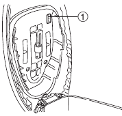
VEHICLE IDENTIFICATION NUMBER
The vehicle identification number  is stamped into the steering head pipe.

MODEL LABEL
The model label is affixed to the seat. This information will be needed to order spare parts.
IMPORTANT INFORMATION
PREPARATION FOR REMOVAL AND DISASSEMBLY
- Before removal and disassembly, remove all dirt, mud, dust and foreign material.
![]()
- Use only the proper tools and cleaning equipment. Refer to the "SPECIAL TOOLS".
![]()
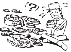
- When disassembling, always keep mated parts together. This includes gears, cylinders, pistons and other parts that have been "mated" through normal wear. Mated parts must always be reused or replaced as an assembly.
- During disassembly, clean all of the parts and place them in trays in the order of disassembly. This will speed up assembly and allow for the correct installation of all parts.
- Keep all parts away from any source of fire.

REPLACEMENT PARTS
Use only genuine Yamaha parts for all replacements. Use oil and grease recommended by Yamaha for all lubrication jobs. Other brands may be similar in function and appearance, but inferior in quality.

GASKETS, OIL SEALS AND O-RINGS
- When overhauling the engine, replace all gaskets, seals and O-rings. All gasket surfaces, oil seal lips and O-rings must be cleaned.
- During reassembly, properly oil all mating parts and bearings and lubricate the oil seal lips with grease.
LOCK WASHERS/PLATES AND COTTER PINS
After removal, replace all lock washers/plates and cotter pins. After the bolt or nut has been tightened to specification, bend the lock tabs along a flat of the bolt or nut.
BEARINGS AND OIL SEALS
Install bearings and oil seals so that the manufacturer's marks or numbers are visible. When installing oil seals, lubricate the oil seal lips with a light coat of lithium-soap-based grease. Oil bearings liberally when installing, if appropriate.
Oil seal

Do not spin the bearing with compressed air because this will damage the bearing surfaces.
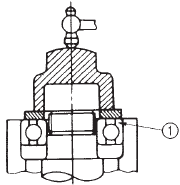
Bearing
CIRCLIPS
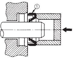
Before reassembly, check all circlips carefully and replace damaged or distorted circlips. Always replace piston pin clips after one use. When installing a circlip , make sure the sharp-edged corner  is positioned opposite the thrust
  that the circlip receives.

 Shaft
Shaft
CHECKING THE CONNECTIONS
Check the leads, couplers, and connectors for stains, rust, moisture, etc.
- Disconnect:
- lead
- coupler
- connector
- Check:
- lead
- coupler
- connector
Moisture → Dry with an air blower.
Rust/stains → Connect and disconnect several times.

- Check:
- all connections
Loose connection → Connect properly.
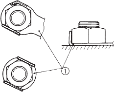
![warning]() NOTE:
NOTE:
If the pin![]() on the terminal is flattened, bend it up.
on the terminal is flattened, bend it up.

- all connections
- Connect:
- lead
- coupler
- connector

- Check:
- continuity (with the pocket tester)
Pocket tester
90890-03132 (YU-03112-C)
![]()

- continuity (with the pocket tester)

 on the terminal is flattened, bend it up.


 NOTE:
NOTE:
- If there is no continuity, clean the terminals. When checking the wire harness, perform steps (1) to (3).
- As a quick remedy, use a contact revitalizer available at most part stores.
SPECIAL TOOLS
The following special tools are necessary for complete and accurate tune-up and assembly. Use only the appropriate special tools as this will help prevent damage caused by the use of inappropriate tools or improvised techniques. Special tools, part numbers or both may differ depending on the country.
When placing an order, refer to the list provided below to avoid any mistakes.
| Tool NO. | Tool name / Function | Illustration |
| 90890-01083(M6) 90890-01085(M8) 90890-01084 | Rocker arm shaft puller bolt  Weight  These tools are used when removing or installing the rocker arm shafts. |  |
| 90890-01235 YU-01235 | Rotor holding tool This tool is used to remove the flywheel magneto. |  |
| 90890-01268 YU-01268 | Ringnut wrench This tool is used to loosen and tighten the exhaust and steering ring nut. |  |
| 90890-01311 YM-08035-A | Valve adjusting tool This tool is necessary for adjusting valve clearance. |  |
| 90890-01312 YM-01312-A | Fuel level gauge This gauge is used to measure the fuel level in the float chamber. |  |
| 90890-01326 YM-01326 90890-01294 YM-01300-1 | T-handle Damper rod holder These tool are used for holding the Damper rod holder when removing or installing the damper rod holder. |  |
| 90890-01337 YM-33285 YM-33285-6 | Clutch spring holder These tool are used for removing the nut with holding the compression spring. |  |
| 90890-01348 YM-01348 | Lock nut wrench This tool is used when removing or installing the secondary sheave nut. |  |
| 90890-01189 YM-01189 | Flywheel puller This tool is used for removing the A.C. magneto rotor. |  |
| 90890-01367 YM-A9409-7 90890-01400 YM-A9409-3 | Fork seal driver weight Fork seal driver attachment(Ø30mm) This tool is used when installing the fork seal. |  |
| 90890-01384 YM-33299 | Oil seal guide This tool is used for protecting the oil seal lip when installing the secondary sliding sheave. |  |
| 90890-01403 YU-33975 | Ring nut wrench This tool is used to loosen and tighten the steering ring nut. |  |
| 90890-01701 YS-01880-A | Sheave holder This tool is used for holding the secondary sheave. |  |
| 90890-03079 YM-34483 | Thickness gauge This tool is used to measure the valve cleanance. |  |
| 90890-03081 YU-33223 | Compression gauge These tool are used to measure the engine compression. |  |
| 90890-03132 YU-03112-C | Pocket tester This instrument is invaluable for checking the electrical system. |  |
| 90890-03113 YU-08036-C | Engine tachometer This tool is needed for detecting engine rpm. |  |
| 90890-03141 YU-03141 | Timing light This tool is needed for detecting ignition timing. |  |
| 90890-04019 YM-04019 90890-04108 YM-04108 | Valve spring compressor Attachment(Ø19mm) These tools are used when removing or installing the valve and the valve spring. |  |
| 90890-06754 YM-34487 | Ignition checker This instrument is necessary for checking the ignition system components. |  |
| 90890-85505 ACC-11001-05-01 | Yamaha bond NO.1215 This sealant (bond) is used for crankcase mating surface, etc. |  |
| 80890-04116 YM-04116 | Valve guide remover (4.5 mm) This tool is used to remove or install the valve guides. |  |
| 90890-04117 YM-04117 | Valve guide installer (4.5 mm) This tool is used to install the valve guides. |  |
| 90890-04099 YM-04099 | Valve guide reamer (5.0 mm) This tool is used to rebore the new valve guides. |  |
SPECIFICATIONS
GENERAL SPECIFICATIONS
| Item | Standard | Limit |
| Model code | 5YR1 (for USA) | ... |
| 5YR2 (for CAN) | ... | |
| Dimensions | ||
| Overall length | 1755 mm (69.1 in) | ... |
| Overall width | 699 mm (27.5 in) | ... |
| Overall height | 1063 mm (41.8 in) | ... |
| Seat height | 759 mm (29.8 in) | ... |
| Wheelbase | 1230 mm (48.4 in) | ... |
| Ground clearance | 95 mm (3.8 in) | ... |
| Minimum turning radius | 1800mm (72 in) | ... |
| Weight | ||
| Wet (without oil and a full fuel tank) | 109 kg (240 lb) | ... |
| Dry (without oil and fuel) | 104kg (229 lb) | ... |
| Maximun load (total of cargo, rider, passenger, and accessories) | 253kg (558 lb) | ... |
ENGINE SPECIFICATIONS
| Item | Standard | Limit |
| Engine | ||
| Engine type | Forced Air cooled 4-stroke, SOHC | ... |
| Displacement | 0.125L(125.0 cm3) | ... |
| Cylinder arrangement | Forward inclined single cylinder | ... |
| Bore × stroke | 51.5 × 60.0 mm | ... |
| Compression ratio | 9.8±0.4:1 | ... |
| Engine idle speed | 1600~1700 r/min | ... |
| Vacuum pressure at engine idle speed | 30.0 kpa (238.6 mmHg) | ... |
| Standard compression pressure (at sea level) | 950 kPa(9.5kg/cm2) / 300 r/mi | ... |
| Fuel | ||
| Recommended fuel | Regular unleaded gasoline | ...... |
| Fuel tank capacity Total (including reserve) | 4.5L (0.98lmp gal, 1.18 USgal) | ... |
| Engine oil | ||
| Lubrication system | Wet sump | ... |
Recommended oil | SAE20W40SE Yamaha 4-cycle oil EFERO X, Z, BX | ... |
| Quantity | ||
| Periodic oil change With oil filter replacement Total amount | 1.0L(0.92 lmp qt, 1.09 US qt) 1.2L(1.10 lmp qt, 1.31 US qt) 1.2L(1.10 lmp qt, 1.31 US qt) | ... ... ... |
| Final gear oil | ||
| Recommended oil Periodic oil change Total amount | SAE85W140S Ehypoid gear oil 0.13L(0.12 lmp qt, 0.14 US qt) 0.15L(0.14 lmp qt, 0.16 US qt) | ... ... ... |
| Oil filter | ||
| Oil filter type | Wire mesh | ... |
| Oil pump | ||
| Oil pump type | Trochoid | ... |
| Inner rotor to outer rotor tip clearance | 0.15 mm | 0.23mm |
| Outer rotor to pump housing clearance | 0.013-0.036 mm | 0.106mm |
| Oil pump housing to inner rotor and outer rotor clearance | 0.06-0.10 mm | 0.17mm |
| Starting system type | Electric and kick starter | ... |
| Spark plug | ||
| Model (manufacturer) × quantity | CR7E (NGK) × 1 | ... |
| Spark plug gap | 0.7~0.8mm | ... |
| Cylinder head | ||
| Volume | 12.3~12.7cm³ | ... |
Max. warpage | ... | 0.03 mm |
| Camshaft | ||
| Drive system | Chain drive (left) | ... |
Intake camshaft lobe dimensions | ||
| Measurement A Measurement B Measurement C | 26.153~26.253 mm 21.015~21.115 mm 5.203mm | 26.053 mm 20.915 mm ... |
Exhaust camshaft lobe dimensions | ||
| Measurement A Measurement B Measurement C | 26.153~26.253 mm 21.056~21.156 mm 5.203 mm | 26.053 mm 20.956 mm ... |
Max. camshaft runout | ... | 0.03 mm |
| Timing chain | ||
| Model/number of links Tensioning system | Morse 92RH2005 / 88 Automatic | ... ... |
| Valve, valve seats, valve guides | ||
| Valve clearance (cold) | ||
| Intake Exhaust | 0.08~0.12 mm 0.13~0.17 mm | ... ... |
Valve dimensions  | ||
| Valve head diameter A | ||
| Intake Exhaust | 23.9~24.1 mm 20.9~21.1 mm | ... ... |
| Valve face width B | ||
| Intake Exhaust | 1.69~2.40 mm 1.69~2.40 mm | ... ... |
| Valve seat width C | ||
| Intake Exhaust | 0.9~1.1 mm 0.9~1.1 mm | 1.6mm 1.6mm |
| Valve margin thickness D | ||
| Intake Exhaust | 0.85~1.15 mm 0.85~1.15 mm | ... ... |
| Valve stem diameter | ||
| Intake Exhaust | 4.475~4.490 mm 4.460~4.475 mm | 4.445 mm 4.430 mm |
| Valve guide inside diameter | ||
| Intake Exhaust | 4.500~4.512 mm 4.500~4.512 mm | 4.550 mm 4.550 mm |
| Valve stem to valve guide clearance | ||
| Intake Exhaust | 0.010~0.037 mm 0.025~0.057 mm | 0.080 mm 0.100 mm |
Valve stem runout | ... | 0.010 mm |
| Valve seat width | ||
| Intake Exhaust | 0.9~1.1 mm 0.9~1.1 mm | 1.6mm 1.6mm |
| Valve springs | ||
| Free length | ||
| Intake Exhaust | 37.30 mm 37.30 mm | 35.40 mm 35.40 mm |
| Installed length (valve closed) | ||
| Intake Exhaust | 25.77mm 25.77mm | ... ... |
| Compressed spring force (installed) | ||
| Intake Exhaust | 147±11N (15.0 ± 1.1 kgf/mm) 147±11N (15.0 ± 1.1 kgf/mm) | ... ... |
Spring tilt | ||
| Intake Exhaust | ... ... | 2.5°/1.6 mm 2.5°/1.6 mm |
| Winding direction (top view) | ||
| Intake Exhaust | Clockwise Clockwise
| ... ... |
| Valve seat reformed | Yes | ... |
| Cylinder | ||
| Cylinder arrangement | Forward inclined single cylinder | ... |
| Bore × stroke | 51.5 × 60mm | ... |
| Compression ratio | 9.8 ± 0.4:1 | ... |
| Bore | 51.49~51.53 mm | ... |
| Max. taper | ... | 0.05 mm |
| Max. out-of-round | ... | 0.05 mm |
| Piston | ||
| Piston-to-cylinder clearance | 0.010~0.030 mm | 0.150mm |
Diameter D | 51.470~51.510 mm | ... |
| Height H | 3.5 mm | ... |
| Piston pin bore (in the piston) | ||
| Diameter | 13.002~13.013 mm | 13.043 mm |
| Offset | 0.35~0.65mm | ... |
| Offset direction | Intake side | ... |
| Piston pin | ||
| Outside diameter | 12.996~13.000 mm | 12.976 mm |
| Piston rings Top ring B  | ||
| Ring type | Barrel | ... |
| Dimensions (B × T) | 1.0 × 2.1mm | ... |
| End gap (installed) | 0.10~0.20 mm | 0.45mm |
| Ring side clearance | 0.02~0.08 mm | 0.13 mm |
2nd ring B | ||
| Ring type | Plain | ... |
| Dimensions (B × T) | 1.0 × 2.1mm | ... |
| End gap (installed) | 0.20~0.30 mm | 0.65mm |
| Ring side clearance | 0.02~0.06 mm | 0.12mm |
Oil ring B | ||
| Dimensions (B × T) | 2.0 × 2.2 mm | ... |
| End gap (installed) | 0.2~0.7 mm | ... |
| Ring side clearance | 0.06~0.15 mm | ... |
| Rocker arm/rocker arm shaft | ||
| Rocker arm inside diameter | 10~10.015mm | ... |
| Rocker arm shaft outside diameter | 9.981~9.991 mm | ... |
| Arm-to-shaft clearance | 0.009~0.034 mm | ... |
| Connecting rod | ||
| Connecting rod length | 97.95~98.05 mm | ... |
| Small end inside diameter | 13.015~13.028mm | ... |
Crankshaft | ||
| Width A | 45.15~45.20 mm | ... |
| Max. runout C | ... | 0.03mm |
| Big end side clearance D | 0.10~0.40 mm | 1.00mm |
| Big end radial clearance E | 0~0.010mm | ... |
| Clutch | ||
| Clutch type Clutch shoe thickness Clutch shoe spring free length Clutch housing inside diameter Compression spring free length Weight outside diameter Clutch-in revolution Clutch-stall revolution | Automatic centrifugal 3.4 ± 0.1 mm 28.0 ± 0.4 mm 120 ± 0.1 mm 113.6 mm 20 ± 0.1 mm 3200±300 r/min 5500±500 r/min | ... 2.0mm ... 120.3mm ... ... ... ... |
| V-belt | ||
| V-belt width | 21.6 mm | 19.5mm |
| Transmission | ||
| Transmission type Primary reduction system Primary reduction ratio Secondary reduction system Secondary reduction ratio Max. main axle runout Max. drive axle runout | V-belt automatic Helical gear 40/15 (2.667) Spur gear 38/13 (2.923) ... ... | ... ... ... ... ... 0.02 mm 0.02 mm |
| Carburetor | ||
| Model (manufacturer) × quantity ID mark Venturi tube bore Main jet Main air jet Jet needle Needle jet Pilot air jet 1 Pilot outlet Pilot jet Bypass 1 Bypass 2 Bypass 3 Valve seat size Starter jet 1 Starter jet 2 Throttle valve size Fuel level ( using fuel level gauge ) Engine idle speed CO% (air induction system ON) CO% (air induction system OFF) Oil temperature (°C) | BS26 (MIKUNI) × 1 5YR 00 Ø22.3 #97.5 0.5 4D×16-1 0-4M 160 0.81 22.5 Ø0.8 Ø1.0 Ø1.1 2.0 40 0.8 115 6.5~7.5mm 1600~1700 r/min 0.2~1.4 % 4.0~5.0 % 70~80°C | ... ... ... ... ... ... ... ... ... ... ... ... ... ... ... ... ... ... ... ... ... ... |
| Throttle bodys | ||
| Model (manufacturer) × quantity Intake vacuum pressure Throttle cable free play (at the flange of the throttle grip) ID mark | 5YR (SAFETY CONTROL CABLE) × 2 30.0kpa (238.6mmHg) 3~5mm 5YR1 | ... ... ... ... |

CHASSIS SPECIFICATIONS


ELECTRICAL SPECIFICATIONS
| Item | Standard | Limit |
| System voltage | 12V | ... |
| Ignition system | ||
| Ignition system type Ignition timing (B.T.D.C.) Advancer type Pickup coil resistance /color C.D.I. unit model (manufacturer) | C.D.I. 5 °/1650 r/min (IDL) Digital 304~456 Ω / WR-WL 5YR00(T-MORIC) | ... ... ... ... ... |
| Ignition coil | ||
| Model (manufacturer) Minimum ignition spark gap Primary coil resistance Secondary coil resistance | 2JN (T-MORIC) 6mm 0.184~0.276 Ω at 20°C 6.32~9.48 kΩ at 20°C | ... ... ... ... |
| Spark plug cap | ||
| Material Resistance | Resin 8~12 kΩ | ... ... |
| Charging system | ||
| System type Model (manufacturer) Nominal output Lighting coil resistance /color Lighting coil resistance /color | C.D.I. magneto 5NW 01 (T-MORIC) 14V 120W / 5000 r/min 0.28~0.42 Ω/B-YR 0.32~0.48 Ω/B-W | ... ... ... ... ... |
| Voltage regulator | ||
| Regulator type Model (manufacturer) No load regulated voltage (DC) | Semiconductor, short circult SH671-12 (XIN DIAN YUAN) 14~15 V | ... ... ... |
| Rectifier | ||
| Model (manufacturer) Rectifier capacity(DC) Withstand voltage | SH671-12 (XIN DIAN YUAN) 8A 200V | ... ... ... |
| Battery | ||
| Battery type (manufacturer) Battery voltage capacity Specific gravity Ten hour rate amperage | GTX7A-BS (GS) 12V 6AH 1.330 6 AH | ... ... ... ... |
| Headlight type | Krypton bulb | ... |
| Indicator light (voltage/wattage×quantity) | ||
| Turn signal indicator light High beam indicator light | 12 V 1.7 W × 1 14 V 3W × 1 | ... ... |
| Bulbs (voltage/wattage × quantity) | ||
| Headlight Tail/brake light Front turn signal light Rear turn signal light Speedometer light Fuel lever meter light | 12 V 60 W/55 W × 1 12 V 8W/27 W × 1 12 V 10 W × 2 12 V 10 W × 2 14 V 3 W ×1 14 V 3 W ×1 | ... ... ... ... ... ... |
| Electric starting system | ||
| System type Starter motor | Constant mesh | ... |
| Model (manufacturer) Suction voltage Power output | 4TE1 (T-MORIC) 12V 0.3 kW | ... ... ... |
| Brushes | ||
| Overall length Quantity Spring force Commutator diameter Commutator resistance Mica undercut (depth) | 10.0 mm 2 5.52~8.28 N 22 mm 0.0306~0.0374 Ω at 20°C 1.5 mm | 3.5mm ... ... 21mm ... ... |
| Starter relay | ||
| Model (manufacturer) Amperage Coil resistance Suction voltage | 3UH1 (SHI LIN) 100 A 3.6-4.4 Ω Below DC8V | ... ... ... ... |
| Horn | ||
| Horn type Model (manufacturer) Max. amperage Performance Coil resistance | Plane AH-368 (ASIA TRAFFIC) 1.5 A 95~105db/2m 4.05~4.55 Ω | ... ... ... ... ... |
| Turn signal relay | ||
| Relay type Model (manufacturer) Self-cancelling device built-in Turn signal blinking frequency Wattage | Semi transistor 5CA9 (TA YOUNG) NO 75~95 cycles/min 10 W × 2 + 1.7 W+ AP | ... ... ... ... ... |
| Fuel sender | ||
| Model (manufacturer) Sender unit resistance-full Sender unit resistance-empty | 5YR1 (CHAO LONG) 4-10 Ω 90-100 Ω | ... ... ... |
| Starting circuit cut-off relay | ||
| Model (manufacturer) Coil resistance | 09-N (SHI LIN) 54~66 Ω | ... ... |
| Thermostat switch | ||
| Model (manufacturer) | 1AJ (NATIONAL) | ... |
| Carburetor heater | ||
| Manufacturer Coil resistance | MIKUNI 30 Ω 20°C | ... ... |
| Fuel lever meter | ||
| Type( manufacturer ) | Moving magneto (CHAO LONG) | ... |
| Fuse (amperage × quantity) | ||
| Main fuse Reserve fuse | 10A×1 10A×1 | ... ... |
CONVERTION TABLE / GENERAL TIGHTENING TORQUE SPECIFICATIONS
CONVERTION TABLE
All specification data in this manual are listed in SI and METRIC UNITS.
Use this table to convert METRIC unit data to IMPERIAL unit data.
Ex.
| METRIC | MULTIPLIER | IMPERIAL |
| ** mm | 0.03937 | ** in |
| 2 mm | 0.03937 | 0.08 in |
CONVERSION TABLE
| METRIC TO IMPERIAL | |||
| Tightening torque | Metric unit | Multiplier | Imperial unit |
| m·kg m·kg c m·kg cm·kg | 7.233 86.794 0.0723 0.8679 | ft·lb in·lb ft·lb in·lb | |
| Weight | kg g | 2.205 0.03527 | lb oz |
| Speed | km/hr | 0.6214 | mph |
| Distance | km m m cm mm | 0.6214 3.281 1.094 0.3937 0.03937 | mi ft yd in in |
| Volume/Capacity | cc (cm3) cc (cm3) lt (liter) lt (liter) | 0.03527 0.06102 0.8799 0.2199 | oz (IMP liq.) cu-in qt (IMP liq.) gal (IMP liq.) |
| Misc. | kg/mm kg/cm2 Centigrade (°C) | 55.997 14.2234 9/5+32 | lb/in psi (lb/in2) Fahrenheit (°F) |
GENERAL TIGHTENING TORQUE SPECIFICATIONS
This chart specifies tightening torques for standard fasteners with a standard ISO thread pitch. Tightening torque specifications for special components or assemblies are provided for each chapter of this manual. To avoid warpage, tighten multi-fastener assemblies in a crisscross pattern and progressive stages until the specified tightening torque is reached. Unless otherwise specified, tightening torque specifications require clean, dry threads. Components should be at room temperature.
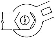
- Width across flats
- Thread diameter
| A (nut) | B (bolt) | General tightening torques | ||
| Nm | m•kg | ft•lb | ||
| 10 mm | 6 mm | 6 | 0.6 | 4.3 |
| 12 mm | 8 mm | 15 | 1.5 | 11 |
| 14 mm | 10 mm | 30 | 3.0 | 22 |
| 17 mm | 12 mm | 55 | 5.5 | 40 |
| 19 mm | 14 mm | 85 | 8.5 | 61 |
| 22 mm | 16 mm | 130 | 13.0 | 94 |
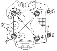
ENGINE TIGHTENING TORQUES


Cylinder head tightening sequence
CHASSIS TIGHTENING TORQUES

NOTE:
- First, tighten the ring nut (lower) approximately 28 Nm (2.8m•kg, 20.3ft•lb) by using the torque-wrench, then loosen the ring nut 1/4 turn.
- Second, tighten the ring nut (lower) approximately 9 Nm (0.9m•kg, 6.5ft•lb) by using the torque-wrench.
- Installing the rubber washer.
- Then finger tighten the center ring nut and touch rubber washer. Align the slots both ring nut and install the lock washer.
- Final, hold the ring nuts (lower and center) and tighten the ring nut (upper) 75Nm (7.5 m•kg, 54.2ft•lb) by using the torque wrench.
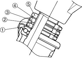
- Lower ring nut
- Rubber washer
- Center ring nut
- Lock washer
- Upper ring nut
LUBRICATION POINTS AND LUBRICANT TYPES
ENGINE LUBRICATION POINTS AND LUBRICANT TYPES


CHASSIS LUBRICATION POINTS AND LUBRICATION TYPES
| Lubrication Point | Lubricant |
| Front wheel oil seal lips |  |
| Frame head pipe bearing (upper and lower) |  |
| Frame head pipe dust seal lips ( lower) |  |
| Tube guide (throttle grip) inner surface |  |
| Brake lever and lever holder bolt sliding surface |  |
| Sidestand and frame sliding surface | |
| Centerstand sliding surface and mounting bolt |  |
| Rear footrest (pin) outside surface | |
| Rear shock absorber backward, bush inner surface and spacer sliding surface |  |
| Seat lock cable and cylinder inner surface |  |
| Engine bracket and engine mound bolt sliding surface |  |
Our customer service e-mail: aservicemanualpdf@yahoo.com
Documents / ResourcesDownload manual
Here you can download full pdf version of manual, it may contain additional safety instructions, warranty information, FCC rules, etc.
Advertisement


Need help?
Do you have a question about the VINO 125 and is the answer not in the manual?
Questions and answers