Advertisement

Self-Repair
This chapter highlights the limited self-repair capabilities of the product.
Prior to performing self-repair, familiarize yourself with the Safety Guidelines and Recommended Equipment sections first as described in the chapter "Disassembly Procedure".
Depending on model, the following key components are eligible for self-repair (if applicable);
- PSU module
- HDD / SSD module
- DIMM module(s)
- WLAN module
- ODD module
If a particular key component is listed and thus would be eligible for self-repair, but is not described in the "Disassembly Procedure" section, then this component is either not present on the respective model, or it is present but embedded on the motherboard and therefore not eligible for self-repair.

Do not attempt to replace other components than those listed above.

For replacement parts, always use only Acer certified components in order to safeguard quality, optimum system performance, stability and reliability of the product.

Any damage to the product that occur during self-repair, or which has occurred as a result of a careless or unsuccessful self-repair attempt, is not covered by the standard product warranty.
Disassembly Procedures
Please refer to the "Disassembly Procedure" chapter for step by step disassembly instructions.
System BIOS & Driver Updates
Visit http://www.acer.com/support to discover the available system BIOS and Drivers for this product. After selecting the desired country/language, either enter the model name or product serial number, or select the product from the list of suggested models in order to get access to product-specific software and documentation.
Updating the System BIOS
- Download the desired system BIOS version from the website.
- Unzip the downloaded file to your computer.
- Double-click the extracted file in order to initiate the update process.
- The update process itself is fully automated and its progress is visualized by means of a progress indicator.
- A visual notification is shown when the update is complete.

Upgrading the system BIOS incorrectly, or intermittence of the system BIOS update process could harm the product.

System BIOS upgrades or downgrades, if not performed by an Acer Service Center or authorized Service Partner, are at own risk.
Updating the Drivers
Run Windows Update in order to get the latest drivers from Acer:
- Select theStart
![]() button.
button. - Go to Settings
![]() > Update & Security
> Update & Security ![]() > Windows Update
> Windows Update ![]() .
. - Available Drivers will be automatically listed on the screen.
- Press Download to start the download of the respective driver.
- Installation of the driver will start automatically once the download is completed.
Should a particular driver not be installed via Windows Update then it is also available for download from the Acer Support website.
To download and install Drivers from the Acer Support website:
- Go to http://www.acer.com and navigate to Support
- Click on Drivers and Manuals
- Enter the device serial number, SNID or model number and press Find
- Click on Drivers to get access to all available drivers for the respective product
- Find the desired driver and click Download
- Extract the file and start the installation
- On-screen instructions will provide guidance through the installation process
After successful driver installation, reboot the device before using it to ensure that the new or updated driver is successfully loaded.
Software Recovery
This product has embedded software recovery tools which can be used to either perform a partial or full software recovery, but also to create a Factory Default recovery media.
For more information about software recovery options, how to perform a software recovery or creating a Factory Default recovery media, please refer to chapter "Recovery" which is available in the User Manual of the product.

In the event of not being able to create a Factory Default recovery media, it is possible to obtain a copy of the recovery media through Acer Customer Service (http://www.acer.com/support).
This is not a free of charge service.
Disassembly Procedure
Safety Guidelines
This chapter contains step by step procedures on how to remove and de-install components from the computer. Use the following safety guidelines to ensure your personal safety. Each procedure included in this chapter assumes that you are preparing your computer for recycling and disposal. By performing any of these procedures you acknowledge that any remaining warranty applicable to your computer will be voided. Before you start any of the procedures in this chapter, make sure to read the following safety guidelines and the respective instructions within the chapter.
- Turn off your computer and disconnect all power sources before opening the computer cover or panels.
- To avoid electrostatic discharge, ground yourself by using a wrist grounding strap or by periodically touching an unpainted metal surface at the same time as touching a connector on the back of the computer.
- Take off any metal objects on your arms or fingers such as bracelets, rings or watches and make sure your hands are completely dry. Even if your unit is unplugged, there may still be some remaining electric charge.
- If a component does not come out easily, do not forcefully remove it. Instead, check that you are removing it correctly and that no wires or other parts are in the way.
- When you disconnect a cable, pull on its connector or on its pull-tab, not on the cable itself. Some cables have connectors with locking tabs; if you are disconnecting this type of cable, press in on the locking tabs before you disconnect the cable.
Recommended Equipment
The following equipment are recommended to do the following maintenance procedures:
- Wrist grounding strap and conductive mat
- Flat screwdriver
- Philips screwdriver
- Polydrive screwdriver
- Plastic tweezers
- Flat plastic pry
WEEE Annex VII Component
These components are classified as requiring selective treatment.
Pre-disassembly Instructions
Do the following prior to starting any maintenance procedures:
- Place the system on a stable work surface.
- Remove AC power cord from the system and peripherals
- Remove all cables from the system.

Make sure the system is completely powered off.
Chassis Door Removal
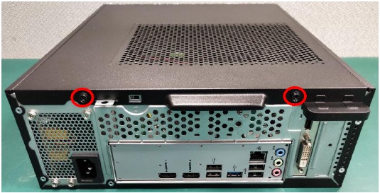
- Opening the chassis and bezel
- Remove the two screws fixed from the side-panel.
![Acer - XC-1780 - Chassis Door Removal - Step 1 Chassis Door Removal - Step 1]()
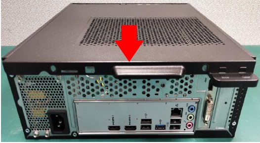
- Shift the left side-panel and take out.
![Acer - XC-1780 - Chassis Door Removal - Step 2 Chassis Door Removal - Step 2]()
- Remove the two screws fixed from the side-panel.
ODD Removal
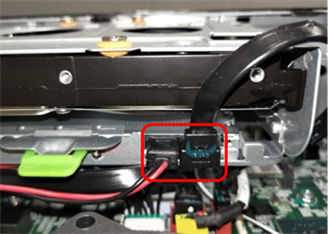
- Remove the ODD
- Disconnect SATA cable and SATA power-cable from slim ODD
![Acer - XC-1780 - ODD Removal - Step 1 ODD Removal - Step 1]()
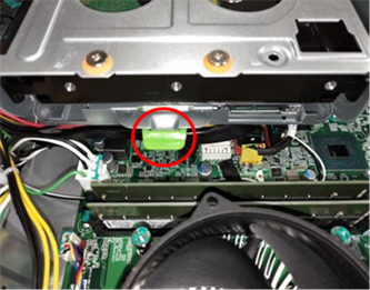
- Remove the screw of slim ODD and take out slim ODD from the Chassis
![Acer - XC-1780 - ODD Removal - Step 2 ODD Removal - Step 2]()
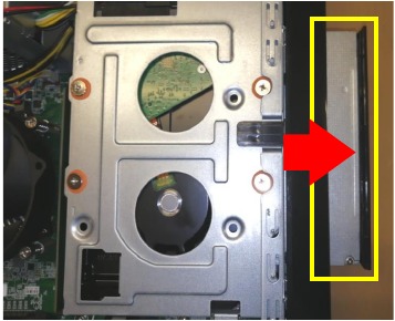
- Remove the ODD
![Acer - XC-1780 - ODD Removal - Step 3 ODD Removal - Step 3]()
NOTE: ODD has been highlighted with the yellow rectangle as above image shows. WEEE Annex VII component.
- Disconnect SATA cable and SATA power-cable from slim ODD
HDD Removal
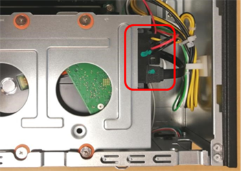
- Remove HDD
- Disconnect the SATA cable and SATA power cable
![Acer - XC-1780 - HDD Removal - Step 1 HDD Removal - Step 1]()
- Remove five screws from chassis
![Acer - XC-1780 - HDD Removal - Step 2 HDD Removal - Step 2]()
- Remove four screws of HDD and take out it from the HDD cage
![Acer - XC-1780 - HDD Removal - Step 3 HDD Removal - Step 3]()
NOTE: HDD has been highlighted with the yellow rectangle as above image shows. WEEE Annex VII component.
- Disconnect the SATA cable and SATA power cable
VGA card Removal
- Remove VGA Card
- Remove the screw of VGA
![Acer - XC-1780 - VGA card Removal - Step 1 VGA card Removal - Step 1]()
- Remove the VGA card from MB
![Acer - XC-1780 - VGA card Removal - Step 2 VGA card Removal - Step 2]()
NOTE: VGA card has been highlighted with the yellow rectangle as above image shows. WEEE Annex VII component.
- Remove the screw of VGA
PSU Removal
- Remove internal PSU
- Disconnect PSU cable
![Acer - XC-1780 - PSU Removal - Step 1 PSU Removal - Step 1]()
- Remove the five screws of PSU
![Acer - XC-1780 - PSU Removal - Step 2 PSU Removal - Step 2]()
- Take out the PSU from chassis
![Acer - XC-1780 - PSU Removal - Step 3 PSU Removal - Step 3]()
NOTE: PSU MB/PSU FAN/PSU CAPACITOR have been highlighted with the yellow rectangle as above image shows. WEEE Annex VII component.
- Disconnect PSU cable
Motherboard, MEM, CPU, Cooler, WLAN, SSD, RTC Battery Removal
- Remove the Main Board
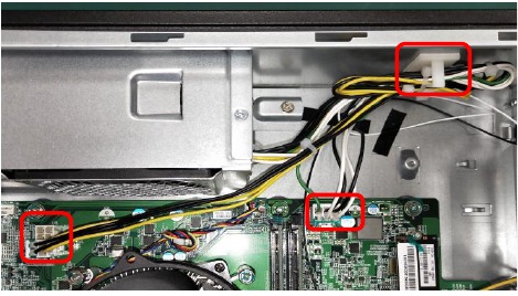
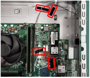
- Remove the adhesive plaster of WLAN antenna
![Acer - XC-1780 - Remove the Main Board - Step 1 Remove the Main Board - Step 1]()
- Remove these six screws from MB then take out MB from chassis
![Acer - XC-1780 - Remove the Main Board - Step 2 Remove the Main Board - Step 2]()
NOTE: Circuit boards >10 cm² has been highlighted with the yellow rectangle as above image shows. Please detach the Circuit boards and follow local regulations for disposal.
- Remove the memory card
![Acer - XC-1780 - Remove the Main Board - Step 3 Remove the Main Board - Step 3]()
NOTE: MEMORY has been highlighted with the yellow rectangle as above image shows. WEEE Annex VII component.
- Loosen these four screws and disconnect CPU fan connector from the MB
![Acer - XC-1780 - Remove the Main Board - Step 4 Remove the Main Board - Step 4]()
NOTE: CPU cooler has been highlighted with the yellow circle as above image shows. WEEE Annex VII component.
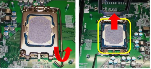
- Remove the CPU
![Acer - XC-1780 - Remove the Main Board - Step 5 Remove the Main Board - Step 5]()
NOTE: CPU has been highlighted with the yellow rectangle as above image shows. WEEE Annex VII component.
- Remove a screw fastening the M.2 SSD and pull it out of slot
![Acer - XC-1780 - Remove the Main Board - Step 6 Remove the Main Board - Step 6]()
NOTE: SSD has been highlighted with the yellow rectangle as above image shows. WEEE Annex VII component.
- Remove the screw, WLAN cover and WLAN card from MB
![Acer - XC-1780 - Remove the Main Board - Step 7 Remove the Main Board - Step 7]()
NOTE: WLAN card has been highlighted with the yellow circle as above image shows. WEEE Annex VII component.
- Remove the battery
![]()
NOTE: RTC battery has been highlighted with the yellow circle as above image shows. WEEE Annex VII component.
- Remove the adhesive plaster of WLAN antenna
Troubleshooting
This chapter provides troubleshooting information for the XC-1780 Service Guide
- Power-On Self-Test (POST)
- POST Error Messages List
Power-On Self-Test (POST)
Each time you turn on the system, the Power-on Self Test (POST) is initiated. Several items are tested during POST, but for the most part transparent to the user.
The Power-On Self Test (POST) is a BIOS procedure that boots the system, initializes and diagnoses the system components, and controls the operation of the power-on password option. If POST discovers errors in system operations at power-on, it displays error messages on screen, generates a check point code at port 80h or even halts the system if the error is fatal.
The main components on the main board that must be diagnosed and/or initialized by POST to ensure system functionality are as follows:
- Microprocessor with built-in numeric co-processor and cache memory subsystem
- Direct Memory Access (DMA) controller
- Interrupt system
- Three programmable timers
- ROM subsystem
- RAM subsystem
- CMOS RAM subsystem and real time clock/calendar with battery backup
- Onboard parallel interface controller
- Embedded hard disk interface and one diskette drive interface
- Keyboard and auxiliary device controllers
- I/O ports
- One parallel port
- One PS/2-compatible mouse port
- One PS/2-compatible keyboard port
POST Error Messages List
If you cannot run the diagnostics program tests but did receive a POST error message, use "POST Error
Messages List "to diagnose system problems. If you did not receive any error message, look for a description of your error symptoms in "Error Symptoms List".
If you are unable to correct the problem by using the "BIOS Messages List" table and "Error Symptoms List" table, go to "Undetermined Problems".
To diagnose a problem, first find the BIOS error messages in the left column. If directed to a check procedure, replace the FRU indicated in the check procedure. If no check procedure is indicated, the first Action/FRU listed in right column is the most likely cause.
| BIOS Messages | Action/FRU |
| BIOS ROM checksum error - System halted | The checksum of the BIOS code in the BIOS chip is incorrect, indicating the BIOS code may have become corrupt. Contact your system dealer to replace the BIOS. |
| CMOS Battery Failed | The CMOS battery is no longer functional. Contact your system dealer for a replacement the BIOS. |
| CMOS Checksum Error- defaults loaded | Checksum of CMOS is incorrect, so the system loads the default equipment configuration. A checksum error may indicate that CMOS has become corrupt. A weak battery may have caused this error. Check the battery and replace if necessary. |
| CPU at run | Displays the running speed of CPU. |
| Display switch is set incorrectly | The display switch on the motherboard can be set to either monochrome or color. This message indicates the switch is set to a different setting than indicated in Setup. Determine which setting is correct, and then either turn off the system and change the jumper, or enter Setup and change the Video selection. |
| Press ESC to skip memory test | The user may press Esc to skip the full memory test. |
| HARD DISK initializing - Please wait a | Some hard drives require extra time to initialize. |
| HARD DISK INSTALL FAILURE | Cannot find or initialize the hard drive controller or the drive. Make sure the controller is installed correctly. If no hard drives are installed, be sure the Hard Drive Selection in Setup is set to NONE. |
| Hard disk(s) diagnosis fail | The system may run specific disk diagnostic Routines. This message appears if one or more hard disks return an error when the diagnostics run. |
| Keyboard Error Or No Keyboard Present | Cannot initialize the keyboard. Make sure the keyboard is attached correctly and no keys are pressed during POST. To purposely configure the system without a keyboard, set the error halt condition in Setup to HALT ON ALL, BUT KEYBOARD. The BIOS then ignores the missing keyboard during POST. |
| Keyboard is locked out - Unlock the key | This message usually indicates that one or more keys have been pressed during the keyboard tests. Be sure no objects are resting on the keyboard. |
| Memory Test: | This message displays during a full memory test, counting down the memory areas being tested. |
| Memory test fail | If POST detects an error during memory testing, additional information appears giving specifics about the type and location of the memory error. |
| Override enabled - Defaults loaded | If the system cannot boot using the current CMOS configuration, the BIOS can override the current configuration with a set of BIOS defaults designed for the most stable, minimalperformance system operations. |
| Press TAB to show POST screen | System OEMs may replace the Phoenix Technologies Award BIOS POST display with their own proprietary display. Including this message in the OEM display permits the operator to switch between the OEM display and the default POST display. |
| Primary master hard disk fail | POST detects an error in the primary master hard drive. |
| Primary slave hard disk fail | POST detects an error in the secondary master hard drive. |
| Secondary master hard disk fail | POST detects an error in the primary slave hard drive. |
| Secondary slave hard disk fail | POST detects an error in the secondary slave hard drive. |
Exploded Diagrams
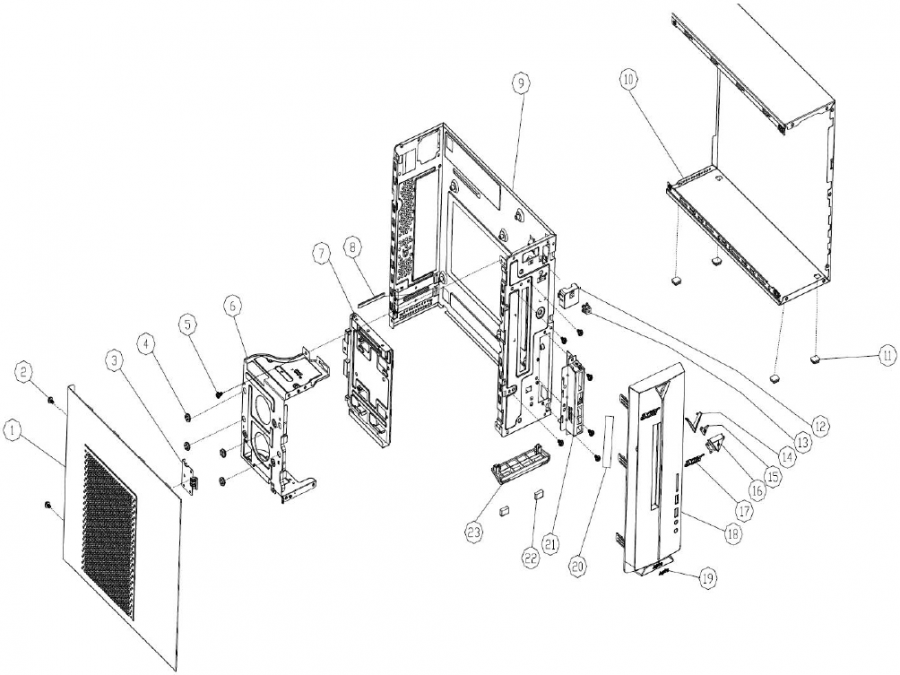
Figure 1 System Exploded Diagram
| Item | Description | Item | Description |
| 1 | Side cover | 12 | Power switch cable |
| 2 | Black #6-32 screw for side cover | 13 | Trim |
| 3 | Metal bracket of side cover | 14 | Power Lens |
| 4 | HDD rubber | 15 | Power switch button |
| 5 | #6-32*5mm screw NI | 16 | Acer logo |
| 6 | HDD metal bracket | 17 | FIO USB metal bracket (with Mylar) |
| 7 | ODD metal bracket | 18 | Main Bezel |
| 8 | Main metal bracket | ||
| 9 | Bottom metal bracket | ||
| 10 | Foot rubber | ||
| 11 | Power switch plastic bracket |
FRU (Field Replaceable Unit) List
Please contact your local service center to find out how to obtain the part or replace your device
To remove your personal data
Whichever option chosen, you are then asked if you want to keep your files or delete everything. To delete your files select Remove Everything, click Next, then click Reset.
- Option 1: Select Start
![]() > Settings
> Settings![]() >Update & Security
>Update & Security ![]() > Recovery. Under Reset this PC, select Get started. Open Recovery settings.
> Recovery. Under Reset this PC, select Get started. Open Recovery settings. - Option 2: Restart your PC to get to the sign-in screen, then press and hold down the Shift key while you select the Power
![]() icon > Restart in the lower-right corner of the screen. After your computer restarts, select Troubleshoot > Reset this PC.
icon > Restart in the lower-right corner of the screen. After your computer restarts, select Troubleshoot > Reset this PC. - Option 3: SelectStart
![]() , then press and hold down the Shift key while you select the Power
, then press and hold down the Shift key while you select the Power ![]() icon > Restart to restart your computer into Recovery Mode. After your computer restarts, select Troubleshoot > Reset this PC.
icon > Restart to restart your computer into Recovery Mode. After your computer restarts, select Troubleshoot > Reset this PC.
Documents / Resources
References
![www.acer.com]() Support | Acer United States
Support | Acer United States![www.acer.com]() Acer Laptops, Desktops, Chromebooks, Monitors & Projectors | Acer United States
Acer Laptops, Desktops, Chromebooks, Monitors & Projectors | Acer United States
Download manual
Here you can download full pdf version of manual, it may contain additional safety instructions, warranty information, FCC rules, etc.
Advertisement









Need help?
Do you have a question about the XC-1780 and is the answer not in the manual?
Questions and answers