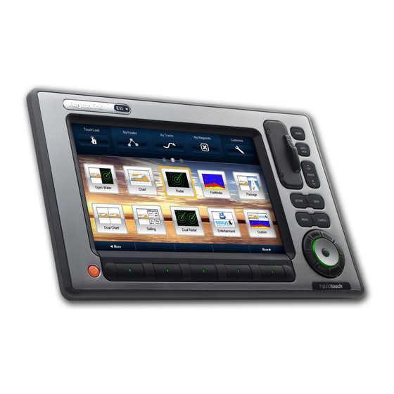
Raymarine E90W Installation Instructions Manual
E-series widescreen multifunction display
Hide thumbs
Also See for E90W:
- User reference handbook (250 pages) ,
- Specifications (15 pages) ,
- Quick reference manual (12 pages)
Table of Contents
Advertisement
Advertisement
Table of Contents
Troubleshooting

Related Manuals for Raymarine E90W


Summary of Contents for Raymarine E90W
- Page 3 Trademarks and registered trademarks Autohelm, HSB, RayTech Navigator, Sail Pilot, SeaTalk and Sportpilot are UK registered trademarks of Raymarine UK Limited. Pathfinder and Raymarine are UK registered trademarks of Raymarine Holdings Limited. 33STV, 45STV, 60STV, AST, Autoadapt, Auto GST, AutoSeastate, AutoTrim, Bidata, G Series, HDFI, LifeTag, Marine Intelligence, Maxiview, On Board, Raychart, Raynav, Raypilot, RayTalk, Raystar, ST40, ST60+, Seaclutter, Smart Route, Tridata, UniControl, Hybridtouch, and Waypoint Navigation are trademarks of Raymarine UK Limited.
-
Page 5: Table Of Contents
Contents Chapter 1 Important information......7 3.1 General cabling guidance .......... 22 3.2 Connections overview ..........23 TFT LCD Displays ............8 3.3 Power connection ............. 23 Water ingress ..............8 3.4 SeaTalk network ............. 26 Disclaimers ..............9 3.5 NMEA 0183 connection ..........34 CompactFlash cards ............ - Page 6 6.9 SeaTalk LED indications.......... 75 6.10 Miscellaneous troubleshooting ......... 76 Chapter 7 Technical support ........77 7.1 Raymarine technical support........78 7.2 3rd party support............79 Chapter 8 Technical specification......81 8.1 Technical specification..........82 Chapter 9 Options and accessories ....... 85 9.1 SeaTalk accessories..........
-
Page 7: Chapter 1 Important Information
This product must be installed and operated in accordance with the Raymarine instructions provided. Failure to do so could result in personal injury, damage Warning: Radar scanner safety to your boat and/or poor product performance. -
Page 8: Tft Lcd Displays
Caution: Power supply protection Caution: Use the sun covers When installing this product ensure the power To protect your product against the damaging source is adequately protected by means of a effects of ultra violet light, always fit the sun suitably-rated fuse or automatic circuit breaker. -
Page 9: Disclaimers
Correct installation is required to ensure that EMC performance is not compromised. Raymarine does not warrant that this product is error-free or that it is compatible with products manufactured by any person or entity For optimum EMC performance we recommend that wherever other than Raymarine. -
Page 10: Suppression Ferrites
Whilst the WEEE Directive does not apply to some Raymarine cables may be fitted with suppression ferrites. These Raymarine products, we support its policy and ask you to be aware are important for correct EMC performance. If a ferrite has to be of how to dispose of this product. -
Page 11: Imo And Solas
Technical accuracy To the best of our knowledge, the information in this document was correct at the time it was produced. However, Raymarine cannot accept liability for any inaccuracies or omissions it may contain. In addition, our policy of continuous product improvement may change specifications without notice. - Page 12 E-Series Widescreen installation...
-
Page 13: Chapter 2 Planning The Installation
Chapter 2: Planning the installation Chapter contents • 2.1 Handbook information on page 14 • 2.2 Installation checklist on page 14 • 2.3 E-Series Widescreen system on page 15 • 2.4 System protocols on page 17 • 2.5 Data master on page 18 •... -
Page 14: Handbook Information
E-Series Widescreen range of multifunction displays. Installation Task The handbook is for use with the following models: Plan your system • E90W Widescreen Multifunction Display Obtain all required equipment and tools • E120W Widescreen Multifunction Display Site all equipment • E140W Widescreen Multifunction Display Route all cables. -
Page 15: E-Series Widescreen System
2.3 E-Series Widescreen system The E-Series Widescreen display can be connected to a variety of equipment as part of your marine electronics system.. Basic system example Planning the installation... - Page 16 Expanded system example Note: The system allows up to 5 E-Series Widescreen displays to be connected on a SeaTalk network. E-Series Widescreen installation...
-
Page 17: System Protocols
2.4 System protocols SeaTalk utilizes a single backbone cable to which compatible instruments connect using a spur. Data and power are carried within the backbone. Devices that have a low draw can be powered from Your Multifunction Display can connect to various instruments and the network, although high current equipment will need to have a displays to share information and so improve the functionality of separate power connection. -
Page 18: Data Master
2.5 Data master international standard to enable equipment from many different manufacturers to be connected together and share information. Any system containing more than one networked multifunction The NMEA 0183 standard carries similar information to SeaTalk. display must have a designated data master. However it has the important difference that one cable will only carry information in one direction. -
Page 19: Pack Contents
2.6 Pack contents Number Description Gasket All models contain the following items: E-Series Widescreen Multifunction Display Bezel Suncover 1.5 m (4.9 ft) Power and data cable Screw pack Document pack, includes: • Multilingual CD • Installation and commissioning instructions • Cutting template •... -
Page 20: Tools
2.7 Tools Tools required for installation E-Series Widescreen installation... -
Page 21: Chapter 3 Cables And Connections
Chapter 3: Cables and connections Chapter contents • 3.1 General cabling guidance on page 22 • 3.2 Connections overview on page 23 • 3.3 Power connection on page 23 • 3.4 SeaTalk network on page 26 • 3.5 NMEA 0183 connection on page 34 •... -
Page 22: General Cabling Guidance
• Unless otherwise stated use only standard cables of the correct type, supplied by Raymarine. Strain relief • Ensure that any non-Raymarine cables are of the correct quality Ensure adequate strain relief is provided. Protect connectors from and gauge. For example, longer power cable runs may require strain and ensure they will not pull out under extreme sea conditions. -
Page 23: Connections Overview
2. Power, data and 1 x video in Power distribution 3. SeaTalk Raymarine recommend that all power connections are made via a 4. Additional 3 x Video in, 1 x video out and alarm audio line out distribution panel. • All equipment must be powered from a breaker or switch, with appropriate circuit protection. -
Page 24: Power Cable
Grounding • for runs of <1 m (3 ft), use 6 mm (#10 AWG) (6 mm) or greater. The following requirements apply when grounding Raymarine • for runs of >1 m (3 ft), use 8 mm (#8 AWG) or greater. - Page 25 The power cable includes an in-line fuse. It is recommended that you fit an additional thermal breaker or fuse at the distribution panel. Display Fuse • C90W / E90W 7 A in-line fuse fitted within power cable. • C120W / E120W •...
-
Page 26: Seatalk Hs Network
3.4 SeaTalk network The SeaTalk network allows you to connect compatible displays and other digital devices. SeaTalk can be used with E-Series Widescreen to: • Create a network of up to 5 E-Series Widescreen displays. • Connect a digital radar scanner. •... - Page 27 The digital radar is usually connected via a SeaTalk switch. On smaller systems (with only one display and no other digital devices) The display is compatible with Raymarine digital radar scanners. the radar may be connected using a crossover coupler. The scanner is connected using a SeaTalk cable.
- Page 28 Radar connected using SeaTalk switch 2. Digital radar scanner 3. SeaTalk switch 4. VCM100 power converter (This is only required with open array type scanners.) 5. Connection to power supply Radar connected directly to the display Note: The connector on the free end of the radar cable does not have a locking / weather tight mechanism.
- Page 29 1. Digital radar scanner 2. Display 3. Crossover coupler 4. Connection to power supply Cables and connections...
- Page 30 Digital radar cable extension If required you can use a Raymarine digital radar extension cable. 1. Extension cable 2. Digital scanner cable Note: The extension cable connects to the radar scanner. Digital radar cables Note: The maximum cable length including all extensions is 25 m (82 ft).
- Page 31 Radar scanner to SeaTalk switch (or crossover coupler) SeaTalk switch (or crossover coupler) to display unit Digital scanner cables SeaTalk network cables Connect the Radar scanner to the SeaTalk switch (or crossover coupler) and Connect from the SeaTalk switch or the crossover coupler into the rear of the power supply.
- Page 32 Sonar connection The E-Series Widescreen display can be used with the following DSM units: The sonar connection is required for fishfinder applications. The display is connected to a sonar module (DSM) using a SeaTalk • DSM400 cable. You will also require a compatible transducer connected to •...
- Page 33 1. DSM unit, e.g. DSM400 Cable Part number Notes 2. Display 1.5 m (4.9 ft) SeaTalk A62245 Cable has waterproof network cable. connectors at both ends. 3. SeaTalk switch 10 m (32.8 ft) SeaTalk A62246 Cable has waterproof 4. Transducer network cable connectors at both ends.
-
Page 34: Nmea 0183 Connection
3.5 NMEA 0183 connection The display has 3 NMEA ports available: • Port 1: Input and output, 4800 / 9600 baud rate. Connections to NMEA 0183 devices are made using the supplied Power and data cable. • Port 2: Input and output, up to 38400 baud rate. •... -
Page 35: Seatalk Connection
3.6 SeaTalk connection SeaTalk cable For SeaTalk cables and extensions, use Raymarine SeaTalk cable Connections to SeaTalk equipment are made using the supplied accessories. multi-cable. Note: Power to SeaTalk instruments is not provided by the display. Cables and connections... -
Page 36: Alarm Connection
3.7 Alarm connection Typical alarm connection An alarm buzzer can be connected using the power / data cable provided with the display. Note: The alarm output is rated for 100 mA maximum load E-Series Widescreen installation... -
Page 37: Gps Connection
3.8 GPS connection High alarm loads and third party alarms You can use the alarm output to switch a relay. This may be useful Depending upon your GPS type it may be either connected via for connecting high loads such as third party alarm sounders or SeaTalk or NMEA 0183. -
Page 38: Ais Connection
3.9 AIS connection Connection using NMEA 0183 A compatible AIS can be connected using SeaTalk or NMEA 0183. Connection using SeaTalk 1. Widescreen display 2. AIS500 transceiver 1. VHF antenna 2. VHF radio 3. AIS unit 4. Display E-Series Widescreen installation... -
Page 39: Fastheading Connection
2. Autopilot course computer a dedicated Fastheading connection. The connection uses NMEA 0183 and can be made to either a compatible Raymarine 3. Autopilot connected via NMEA 0183 (Fastheading and other autopilot or a dedicated Fastheading sensor. If your system includes... -
Page 40: Seatalk Ng Connections
3.11 SeaTalk connections Typical SeaTalk system The display can connect as part of a SeaTalk network. The display can use SeaTalk to communicate with: • SeaTalk instruments (e.g. ST70) • SeaTalk autopilots (e.g. ST70 with SmartPilot SPX course computer) E-Series Widescreen installation... -
Page 41: Nmea 2000 Connection
The SeaTalk bus requires a 12 V power supply. This may be provided from: • Raymarine equipment with a regulated 12 V supply. (e.g. a SmartPilot SPX course computer) • Other suitable 12 V supply. Note: SeaTalk does NOT supply power to multifunction displays and other equipment with a dedicated power supply input. -
Page 42: Video And Alarm Audio Connection
3.13 Video and alarm audio connection 3. SeaTalk to DeviceNet adaptor cable 4. NMEA 2000 equipment The display supports connection of up to 4 video devices and an external monitor. It also provides an alarm audio output for Connecting the display to an existing NMEA 2000 (DeviceNet) connection to the ship’s audio system. - Page 43 Video and alarm audio connection 4. Video connection (x 4) 5. VGA connection to external monitor 6. Audio out (line level to appropriate amplifier) Video connection colors Black Yellow Green Blue Video and alarm audio cables These are the cables which provide connections for video devices, an external monitor and an alarm audio signal.
- Page 44 Video and audio cables Cable Part number Notes 1.5 m (4.9 ft) Power and R62131 Supplied with the data cable display. Provides 1 x video input A62158 Available as an 5 m (16.4 ft) Video/Alarm audio cable accessory. This cable provides: •...
-
Page 45: Chapter 4 Location And Mounting
Chapter 4: Location and mounting Chapter contents • 4.1 Selecting a location on page 46 • 4.2 Flush mounting on page 48 • 4.3 Bracket (trunnion) mounting on page 49 • 4.4 Front bezel on page 51 Location and mounting... -
Page 46: Selecting A Location
As display contrast, color and night mode performance are all Ensure the unit is mounted in a location which allows proper affected by the viewing angle, Raymarine recommends you routing and connection of cables: temporarily power up the display when planning the installation, to –... - Page 47 Widescreen display dimensions Viewing angle Note: The angles are provided for a contrast ratio of equal to or greater than 10. Location and mounting...
-
Page 48: Flush Mounting
4.2 Flush mounting The standard method for mounting the display is a flush or panel mounting arrangement. Before mounting the unit, ensure that you have: • Selected a suitable location • Identified the cable connections and route that the cables will take •... -
Page 49: Bracket (Trunnion) Mounting
4.3 Bracket (trunnion) mounting 5. Ensure that the unit fits into the removed area and then file around the cut edge until smooth. The display can be mounted on an optional bracket. 6. Drill four 4.5 mm (3/16 in) holes as indicated on the template to accept the securing bolts. - Page 50 Note: Bracket (trunnion) mounting kit is available as an optional accessory. 1. Mark the location of the mounting bracket screw holes on the chosen mounting surface. 2. Drill pilot holes for the screws using a suitable drill, taking care that there are no cables or anything that may be damaged behind the surface.
-
Page 51: Front Bezel
4.4 Front bezel Attaching the front bezel Before fitting the bezel you must have mounted the unit in its required location. 1. Carefully lift one edge of the screen protection film, so that it is accessible for removing when unit installation is complete. 2. -
Page 52: Removing The Front Bezel
Removing the front bezel 3. Unclip the right hand edge. The bezel should now come away from the display easily. Important: Use care when removing the bezel. Do not use any tools to lever the bezel, doing so may cause damage. 1. -
Page 53: Chapter 5 System Checks
Chapter 5: System checks Chapter contents • 5.1 Initial power on test on page 54 • 5.2 Designating the data master on page 55 • 5.3 GPS check on page 55 • 5.4 Radar check on page 56 • 5.5 Sonar check on page 58 •... -
Page 54: Initial Power On Test
• Panning the chart display. Powering the display on • Placing and moving the cursor. 1. Press and hold the POWER button until the Raymarine logo • Placing and moving VRMs and EBLs. appears. 2. Press OK to acknowledge the warning window. -
Page 55: Designating The Data Master
5.2 Designating the data master 5.3 GPS check The following task must be performed on the multifunction display Checking GPS operation that you want to designate as the data master: You can check that the GPS is functioning correctly using the chart 1. -
Page 56: Radar Check
5.4 Radar check Typical HD digital radar screen Warning: Radar scanner safety Before rotating the radar scanner, ensure all personnel are clear. Warning: Radar transmission safety The radar scanner transmits electromagnetic energy. Ensure all personnel are clear of the scanner when the radar is transmitting. - Page 57 2. Select the PARKING OFFSET option, then adjust the offset angle required to park the radar so that the antenna comes to rest facing forward (you should see the Raymarine logo wording Checking the bearing alignment from the front of the vessel) when you place it in either standby or switch it off.
-
Page 58: Sonar Check
5.5 Sonar check Warning: Sonar operation • NEVER operate the sounder with the boat out of the water. • NEVER touch the transducer face when the sounder is powered on. • SWITCH OFF the sounder if divers are likely to be within 25 ft (5 m) of the transducer. -
Page 59: Language Selection
5.6 Language selection 5.7 Setting up Autopilot, AIS and Navtex The system can operate in the following languages: Some setting up is required to enable integration of Autopilot, AIS and Navtex equipment connected as part of your system. English (US) English (UK) Chinese 1. -
Page 60: System Setup Menu
5.8 System setup menu The following table describes the various options in the System Setup menu for your multifunction display. Menu item Description Options Position Mode Determines how positioning data is displayed — as • Lat/Long (default) Latitude/Longitude coordinates, or Loran TDs. •... - Page 61 Menu item Description Options Variation Source This setting compensates for the naturally occuring offset • Auto (compensation value displayed in of the earth’s magnetic field. When set to Auto, the system brackets) (default) automatically compensates, and displays the compensation • Manual value in brackets.
- Page 62 Menu item Description Options Settings and Data Reset Resets all system setup menus, including page sets and the Factory Reset confirmation databar, to the factory default settings. Waypoints, routes and • YES tracks ARE deleted. • NO Note: For systems using multiple multifunction displays (networked displays), the complete system database is deleted on the data master (primary display).
- Page 63 Menu item Description Options Units Setup Enables you to specify the units used for the following key Distance Units measurements: • Nautical Miles (default) • Distance • Statute Miles • Speed • Kilometers • Depth Speed Units • Temperature • Knots (default) •...
- Page 64 Menu item Description Options • Liters System Integration Determines the connection settings for external equipment. The Autopilot Control following items are available in the sub-menu: • Disabled (default) • Autopilot Control — If set to Enabled, this option allows you •...
- Page 65 Menu item Description Options to OFF to ensure that all NMEA-connected units receive • OFF (default) heading data from the external heading sensor. • ALL • SeaTalk2 Keyboard — Set to ONE or ALL if you have a SeaTalk2 keyboard connected. Otherwise, set to OFF. •...
- Page 66 Menu item Description Options • VTG • ZDA NMEA Port Setting • NMEA 4800 (default) • Navtex 4800 • Navtex 9600 • AIS 38400 Enable Password Waypoint Password Setup This menu allows you to enable password protection for waypoints, and to change the password. •...
-
Page 67: Chapter 6 Troubleshooting
Chapter 6: Troubleshooting Chapter contents • 6.1 Troubleshooting on page 68 • 6.2 Power up troubleshooting on page 69 • 6.3 Radar troubleshooting on page 70 • 6.4 GPS troubleshooting on page 71 • 6.5 Sonar troubleshooting on page 72 •... -
Page 68: Troubleshooting
The troubleshooting information provides possible causes and corrective action required for common problems associated with marine electronics installations. All Raymarine products are, prior to packing and shipping, subjected to comprehensive test and quality assurance programs. However, if you experience problems with the operation of your E-Series Widescreen multifunction display, this section will help you to diagnose and correct problems in order to restore normal operation. -
Page 69: Power Up Troubleshooting
6.2 Power up troubleshooting Problems at power up and their possible causes and solutions are described here. Problem Possible causes Possible solutions The display does not start up. Problem with power to the unit. Check relevant fuses and breakers. Check that the power supply cable is sound and that all connections are tight and free from corrosion. -
Page 70: Radar Troubleshooting
Switch. Check that SeaTalk cables are free from damage. Software mismatch between equipment Contact Raymarine technical support. may prevent communication. Switch at scanner pedestal in OFF position Ensure scanner pedestal switch is in ON position. Intermittent or poor power connection Radar will not initialize (Voltage control Check power connection at VCM. -
Page 71: Gps Troubleshooting
6.4 GPS troubleshooting Problems with the GPS and their possible causes and solutions are described here. Problem Possible causes Possible solutions “No Fix” GPS status icon is displayed. Geographic location or prevailing Check periodically to see if a fix is obtained in better conditions or another conditions preventing satellite fix. -
Page 72: Sonar Troubleshooting
Check the status of the SeaTalk Switch. Check that SeaTalk cables are free from damage. Software mismatch between equipment Contact Raymarine technical support. may prevent communication. Problematic depth readings or sonar Gain or Frequency settings may be Check the fishfinder presets, gain and frequency settings. -
Page 73: System Data Troubleshooting
Check the power to the SeaTalk bus. Refer to the manufacturer’s handbook for the equipment in question. Software mismatch between equipment Contact Raymarine technical support. may prevent communication. Instrument or other system data is missing SeaTalk network problem Check that all required equipment is connected to the SeaTalk switch. -
Page 74: Video Troubleshooting
6.7 Video troubleshooting Problems with the video inputs and their possible causes and solutions are described here. Problem Possible causes Possible solutions No signal message on screen (video Cable or connection fault Check that the connections are sound and free from corrosion. image not displayed) Only 1 video connection available Video inputs 2, 3 and 4 are on a separate... -
Page 75: Touchscreen Troubleshooting
6.8 Touchscreen troubleshooting Problems with the touchscreen and their possible causes and solutions are described here. Problem Possible causes Possible solutions Touchscreen does not operate as Touch lock is enabled Use the Trackpad to turn off the touch lock on the home screen. expected Screen is not being operated with bare Bare fingers must make contact with the screen for correct operation. -
Page 76: Miscellaneous Troubleshooting
Ensure that the front bezel is fitted correctly and that all buttons are free to operate correctly. Software mismatch on system (upgrade Go to www.raymarine.com and click on support for the latest software required). downloads. Corrupt data / other unknown issue. -
Page 77: Chapter 7 Technical Support
Chapter 7: Technical support Chapter contents • 7.1 Raymarine technical support on page 78 • 7.2 3rd party support on page 79 Technical support... -
Page 78: Raymarine Technical Support
Web support Please visit the customer support area of our website at: www.raymarine.com This contains Frequently Asked Questions, servicing information, e-mail access to the Raymarine Technical Support Department and details of worldwide Raymarine agents. Telephone support In the USA call:... -
Page 79: 3Rd Party Support
7.2 3rd party support Contact and support details for 3rd party suppliers can be found on the appropriate websites. Navionics www.navionics.com Sirius marine weather www.sirius.com/marineweather Sirius audio www.sirius.com Technical support... - Page 80 E-Series Widescreen installation...
-
Page 81: Chapter 8 Technical Specification
Chapter 8: Technical specification Chapter contents • 8.1 Technical specification on page 82 Technical specification... -
Page 82: Technical Specification
4 A peak operating current colors) Resolution Power consumption Typical power consumption at full brightness: • E90W: 9 in display, 800 x 480 pixels • E90W: 23 W • E120W: 12 in display, 1280 x 800 • E120W: 35 W pixels •... - Page 83 Data connections. • 3 x NMEA 0183 ports: Electronic charts Embedded electronic charts – NMEA port 1: I/O 4800/9600 • Navionics (embedded cartography baud appropriate to purchase region; North America, Europe or Rest of – NMEA port 2: I/O World, as appropriate) 4800/9600/38400 baud Compatible chart cards –...
- Page 84 E-Series Widescreen installation...
-
Page 85: Chapter 9 Options And Accessories
Chapter 9: Options and accessories Chapter contents • 9.1 SeaTalk accessories on page 86 • 9.2 SeaTalk accessories on page 86 • 9.3 SeaTalk accessories on page 87 • 9.4 Spares and accessories on page 89 Options and accessories... -
Page 86: Seatalk Accessories
9.1 SeaTalk accessories 9.2 SeaTalk accessories SeaTalk cables and accessories for use with compatible products. SeaTalk cables and accessories for use with compatible products. Description Part No Notes Description Part No Notes NMEA / SeaTalk E85001 converter Backbone Kit A25062 Includes: D285 3 m (9.8 ft) SeaTalk... -
Page 87: Seatalk Hs Accessories
9.3 SeaTalk accessories Description Part No Notes Digital radar scanner cables SeaTalk 3 m (9.8 ft) A06035 Scanner cables backbone Connect the Radar scanner to either the SeaTalk switch or the crossover coupler. SeaTalk 5 m (16.4 ft) A06036 backbone Cable Part number Notes... - Page 88 SeaTalk network cables SeaTalk hardware Cable Part number Notes SeaTalk network cables SeaTalk switch E55058 8 way hub for network Standard network cables connect compatible equipment to the SeaTalk switch (or connection of multiple crossover coupler), they have a waterproof connector at one end. SeaTalk devices.
-
Page 89: Spares And Accessories
Part No Notes This cable provides: Trunnion (bracket) A62132 • 3 x video input BNC mount kit (C90W / connectors E90W) • 1 x VGA video output Trunnion (bracket) A62133 connector mount kit (C120W / E120W) • 1 x RCA phono... - Page 90 Service spares E90W Bonded R62249 Service spares are available to service dealers only. Touchscreen Assembly E120W Bonded R62250 Description Part No Notes Touchscreen Assembly Chart door R62184 E140W Bonded R62251 Touchscreen Assembly Seal Set (C90W / E90W) R62186 E-Series Widescreen installation...
- Page 91 Description Part No Notes Rotary encoder PCB R62252 assembly I/O PCB Assembly R62253 CPU PCB Assembly R62254 Keymat Set R62270 SSD PCB Assembly — R62255 US version SSD PCB Assembly — R62298 EU version SSD PCB Assembly — R62299 ROW version UniControl R62313 Options and accessories...
- Page 92 E-Series Widescreen installation...
-
Page 93: Appendix A Multifunction Display System Integration
Appendix A Multifunction display display, and the type of connectivity (in terms of protocols and physical interfaces) that they use to exchange data with the display: system integration You can connect a number of external devices to your multifunction Device Type Suitable Devices Connectivity display, providing additional features and functions. - Page 94 • Navionics Fish’N Chip • Navionics Hotmaps VHF radio Raymarine DSC VHF NMEA 0183, SeaTalk radios Refer to the Raymarine website Additional Multifunction E90W, E120W, E140W, SeaTalk, SeaTalk (www.raymarine.com) Display(s) SeaTalk for the latest list of Video/camera Composite PAL or NTSC BNC connector supported chart cards.
-
Page 95: Appendix B Nmea 0183 Sentences
Appendix B NMEA 0183 sentences Recommended minimum specific GPS transit data The display supports the following NMEA 0183 sentences. These are applicable to NMEA 0183 and SeaTalk protocols. Course over ground and ground speed Time and date Transmit Wind speed and angle Autopilot b Routes sentence Bearing and distance to waypoint... - Page 96 Geographic position loran c sentence Cross track error measured sentence Time and date sentence Geographic position latitude longitude Meteorological composite sentence sentence GPS satellite fault detection data GPS DOP and active satellites sentence sentence Routes sentence GPS satellites in view sentence Waypoint location sentence Heading deviation and variation sentence...
-
Page 97: Appendix C Nmea 2000 Sentences
Appendix C NMEA 2000 sentences The display supports the following NMEA 2000 sentences. These are applicable to NMEA 2000, SeaTalk and SeaTalk 2 protocols. Message number Message description Transmit Receive Bridge ● ● ● 59392 ISO Acknowledgment ● 59904 ISO Request ●... - Page 98 Message number Message description Transmit Receive Bridge ● ● ● 129026 COG SOG rapid update ● ● ● 129029 GNSS position data ● ● ● 129033 Time and date ● 129038 AIS Class A Position Report ● 129039 AIS Class B Position Report ●...
-
Page 99: Appendix D Connectors And Pinouts
Message number Message description Transmit Receive Bridge ● ● ● 130310 Environmental parameters ● 130311 Environmental parameters message ● 130576 Small craft status ● ● ● 130577 Direction data ● 130578 Vessel speed components Item Remarks Appendix D Connectors and pinouts Current source to network No current sourced for external Power, data and video connector... - Page 100 Group- Group- Signal Cable Color Signal Cable Color NMEA1 7/0.15 Twisted Yello 7/0.15 White / pair BATT- Black NMEA1 7/0.15 Brown VIDEO RG179 75R coax (or equiva- NMEA1 7/0.15 Twisted White lent) pair VIDEO Screen NMEA1 7/0.15 Green NMEA2 7/0.15 Twisted Orange / Video and alarm-audio connector...
- Page 101 VIDEO OUT V-SYNC GROUND SHIELD Not connected VIDEO OUT GREEN Not connected SHIELD VIDEO OUT GREEN GROUND Not connected VIDEO OUT BLUE Not connected VIDEO OUT BLUE GROUND Note: Use only Raymarine cables when connecting to SeaTalk SeaTalk connector Connectors and pinouts...
- Page 102 Current source to network No current sourced for external devices Current sink from network <160mA (Interface drive only) Signal +12V Screen CanH CanL SeaTalk (not connected on C / E-Series Widescreen) Note: Use only Raymarine cables when connecting to SeaTalk E-Series Widescreen installation...
Need help?
Do you have a question about the E90W and is the answer not in the manual?
Questions and answers