Table of Contents
Advertisement
Advertisement
Table of Contents

Related Manuals for MSI K8T Neo2-F


Summary of Contents for MSI K8T Neo2-F
- Page 1 K8T Neo2 Series MS-6702E (v1.X) ATX Mainboard G52-M6702E4...
- Page 2 Manual Rev: 1.2 Release Date: August 2004 FCC-B Radio Frequency Interference Statement This equipment has been tested and found to comply with the limits for a class B digital device, pursuant to part 15 of the FCC rules. These limits are designed to provide reasonable protection against harmful interference when the equipment is operated in a commercial environment.
-
Page 3: Copyright Notice
Copyright Notice The material in this document is the intellectual property of MICRO-STAR INTERNATIONAL. We take every care in the preparation of this document, but no guarantee is given as to the correctness of its contents. Our products are under continual improvement and we reserve the right to make changes without notice. -
Page 4: Technical Support
Alternatively, please try the following help resources for further guidance. Visit the MSI homepage & FAQ site for technical guide, BIOS updates, driver updates, and other information: http://www.msi.com.tw & http://www.msi. -
Page 5: Table Of Contents
CONTENTS Chapter 1. Getting Started ................... 1-1 Mainboard Specifications .................. 1-2 Mainboard Layout ....................1-4 Packing Contents ....................1-5 Chapter 2. Hardware Setup ................. 2-1 Quick Components Guide .................. 2-2 Central Processing Unit: CPU ................2-3 CPU Installation Procedures for Socket 939 ..........2-4 Installing AMD Athlon64 / Athlon 64 FX CPU Cooler Set ...... - Page 6 Chassis Intrusion Switch Connector: JCASE1 ........2-22 Power Saving Switch Connector: JGS1 ..........2-22 D-Bracket™ 2 Connector: JLED (Optional) ..........2-22 Jumpers ......................2-25 Clear CMOS Jumper: JBAT1 ..............2-25 Slots ........................2-26 AGP (Accelerated Graphics Port) Slot ........... 2-26 PCI (Peripheral Component Interconnect) Slots ........
- Page 7 Power On ....................4-18 Power Off / Restart .................. 4-19 Start With ....................4-19 Auto Login ....................4-20 Chapter 5. VIA VT8237 Serial ATA RAID & Promise FastTrak579 Parallel ATA / Serial ATA RAID (Optional) Introduction ......5-1 Introduction ......................... 5-2 System BIOS Setup ....................
- Page 8 Arrays Under Windows ..................5-30 Create an Array ....................5-30 Array Functional ....................5-32 Array Critical ....................5-33 Array Offline ....................5-34 Rebuild an Array ....................5-35 Synchronize an Array ..................5-36 Array Conversion / Expansion ................ 5-38 Delete an Array ....................5-41 viii...
-
Page 9: Chapter 1. Getting Started
Getting Started Chapter 1. Getting Started Getting Started Thank you for purchasing K8T Neo2 (MS-6702E v1.X) ATX ® mainboard. The K8T Neo2 is based on VIA K8T800 Pro North Bridge & VT8237 South Bridge chipsets and provides eight USB 2.0 ports for high-speed data transmission, RealTek ALC850 chip for 7.1-channel audio output, and a SPDIF interface for digital audio ®... -
Page 10: Mainboard Specifications
® Supports 64-bit AMD Athlon 64 and Athlon 64 FX processor (Socket 939) Supports up to 3500+, 3800+ Athlon 64 FX 53, or higher CPU (For the latest information about CPU, please visit http://www.msi.com.tw/program/ products/mainboard/mbd/pro_mbd_cpu_support.php) Chipset ® K8T800 Pro chipset... - Page 11 ATX Form Factor: 30.4 cm (L) x 24.4 cm (W) Mounting 9 mounting holes MSI Reminds You... 1. Please note that users cannot install OS, neither WinME nor Win98, in their SATA hard drive. Under these two OSs, SATA can only be used as a normal storage device.
-
Page 12: Mainboard Layout
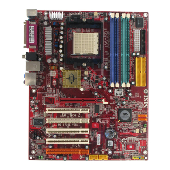
MS-6702E ATX Mainboard Mainboard Layout T: mouse CFAN1 B: keyboard (Optional) (Optional) SPDIFOut B:USB port T: LAN jack B: USB ports Line-In Line-Out T:RS-Out M:CS-Out B:SPDIFOut AG P Slot Vt6306 (Optional) PCI Slot 1 SATA2 PCI Slot 2 SATA1 RTL8110S PCI Slot 3 IDE3 PCI Slot 4... -
Page 13: Packing Contents
Getting Started Packing Contents MSI Driver/Utility SATA Cable (Optional) MSI motherboard CD & diskette Round Cable of Power Cable (Optional) D-Bracket 2 (Optional) IDE Devices Round Cable of User’s Guide Back IO Shield Floppy Disk... -
Page 14: Chapter 2. Hardware Setup
Hardware Setup Chapter 2. Hardware Setup Hardware Setup This chapter tells you how to install the CPU, memory modules, and expansion cards, as well as how to setup the jumpers on the mainboard. Also, it provides the instructions on connecting the peripheral devices, such as the mouse, keyboard, etc. -
Page 15: Quick Components Guide
MS-6702E ATX Mainboard Quick Components Guide DDR DIMMs, CFAN1, p.2-15 JPW1, p.2-10 p.2-7 JCASE1, p.2-21 Back Panel FDD1, p.2-15 I/O, p.2-11 JWR1, p.2-10 IDE1/2, p.2-16 SFAN1, p.2-15 SATA1, SATA2, AGP1, p.2-25 p.2-17 JGS1, p.2-21 PCI Slots 1~5, JBAT1, p.2-24 p.2-25 PWF_FAN1/2, p.2-15 JCD1, p.2-19... -
Page 16: Central Processing Unit: Cpu
If you do not have the heat sink and cooling fan, contact your dealer to purchase and install them before turning on the computer. For the latest information about CPU, please visit http://www.msi.com.tw/program/ products/mainboard/mbd/pro_mbd_cpu_support.php. MSI Reminds You... -
Page 17: Cpu Installation Procedures For Socket 939
MS-6702E ATX Mainboard CPU Installation Procedures for Socket 939 1. Please turn off the power and Open Lever unplug the power cord before installing the CPU. Sliding 90 degree Plate 2. Pull the lever sideways away from the socket. Make sure to raise the lever up to a 90-de- gree angle. -
Page 18: Installing Amd Athlon64 / Athlon 64 Fx Cpu Cooler Set
Hardware Setup Installing AMD Athlon 64 / Athlon 64 FX CPU Cooler Set When you are installing the CPU, make sure the CPU has a heat sink and a cooling fan attached on the top to prevent overheating. If you do not have the heat sink and cooling fan, contact your dealer to purchase and install them before turning on the computer. - Page 19 Safety Hook Fixed Lever Fixed Bolt MSI Reminds You... While disconnecting the Safety Hook from the fixed bolt, it is neces- sary to keep an eye on your fingers, because once the Safety Hook is disconnected from the fixed bolt, the fixed lever will spring back instantly.
-
Page 20: Memory
Hardware Setup Memory The mainboard provides 4 slots for 184-pin DDR SDRAM DIMM (Double In-Line Memory Module) modules and supports the memory size up to 4GB. You can install DDR266/ 333/400 modules on the DDR DIMM slots (DDR 1~4). DIMM4~1 (from left to right) DIMM Module Combination Install at least one DIMM module on the slots. -
Page 21: Recommended Memory Combination List
DIMM Slot GREEN slots PURPLE slots Max Speed DIMM1 DIMM2 DIMM3 DIMM4 DDR 400 DDR 400 DDR 400 DDR 400 DDR 400 DDR 333 S: Single Side D: Double Side For the updated supporting memory modules, please visit http://www.msi.com.tw/ program/products/mainboard/mbd/pro_mbd_trp_list.php. -
Page 22: Installing Ddr Modules
Hardware Setup MSI Reminds You... 1. The maximum memory speed decreases when the following Memory Combination is selected (you can also refer to the Rec- ommended Memory Combination list shown in the previous page: - Each channel is installed with two double-sided memory modules 2. -
Page 23: Power Supply
JPW1 Pin Definition SIGNAL JPW1 MSI Reminds You... 1. These two connectors connect to the ATX power supply and have to work together to ensure stable operation of the mainboard. 2. Power supply of 300 watts (or above) is highly recommended for system stability. -
Page 24: Back Panel
Hardware Setup Back Panel The back panel provides the following connectors: Line-In Line-Out SPDIF Parallel Mouse Keyboard COM A Mini USB Ports 1394 Port Rear Speaker-Out (Optional) Center/Subwoofer Speaker-Out 1394 Port SPDIF-Out (Optional) Mouse Connector (Green) ® The mainboard provides a standard PS/2 mouse mini DIN connector for attaching a PS/2 ®... -
Page 25: Serial Port Connector
MS-6702E ATX Mainboard Serial Port Connector The mainboard offers one 9-pin male DIN connector as the serial port. The port is a 16550A high speed communication port that sends/receives 16 bytes FIFOs. You can attach a serial mouse or other serial devices directly to the connector. Pin Definition 1 2 3 4 5 SIGNAL... -
Page 26: Rj-45 Lan Jack
Hardware Setup RJ-45 LAN Jack The mainboard provides one standard RJ-45 jack for connection to Local Area Net- work (LAN). Giga-bit LAN enables data to be transferred at 1000, 100 or 10Mbps. You can connect a network cable to the LAN jack. Activity Indicator Link Indicator RJ-45 LAN Jack... -
Page 27: Audio Port Connectors
MS-6702E ATX Mainboard Audio Port Connectors The left 3 audio jacks are for 2-channel mode for stereo speaker output: Line Out is a connector for Speakers or Headphones. Line In is used for external CD player, Tape player, or other audio devices. Mic is a connector for microphones. However, there is an advanced audio application provided by Realtek ALC850 to offer support for 7.1-channel audio operation and can turn rear audio connectors from 2-channel to 4-/5.1-channel audio. -
Page 28: Parallel Port Connector: Lpt1
Hardware Setup Parallel Port Connector: LPT1 The mainboard provides a 25-pin female centronic connector as LPT. A parallel port is a standard printer port that supports Enhanced Parallel Port (EPP) and Extended Capabilities Parallel Port (ECP) mode. Pin Definition SIGNAL DESCRIPTION STROBE Strobe... -
Page 29: Connectors
SFAN1 PWF_FAN1 PWF_FAN2 CFAN1 MSI Reminds You... 1. Always consult the vendors for proper CPU cooling fan. 2. CFAN1 supports the fan control. You can install Core Center utility that will automatically control the CPU fan speed according to the actual CPU temperature. -
Page 30: Hard Disk Connectors: Ide1/Ide2
IDE2 (Secondary IDE Connector) IDE2 can also connect a Master and a Slave drive. MSI Reminds You... If you install two hard disks on cable, you must configure the second drive to Slave mode by setting its jumper. Refer to the hard disk documentation supplied by hard disk vendors for jumper setting instructions. -
Page 31: Serial Ata/Serial Ata Raid Connectors Controlled By
MS-6702E ATX Mainboard Serial ATA/Serial ATA RAID Connectors con- trolled by VT8237: SATA1/SATA2 The Southbridge of this mainboard is VT8237 which supports SATA2 two serial connectors SATA1 and SATA2. SATA1 SATA1 & SATA2 are dual high-speed Serial ATA interface ports. Each supports 1 generation serial ATA data rates of 150 MB/s. -
Page 32: Front Panel Audio Connector: Jaud1
Hardware Setup MSI Reminds You... Please do not fold the serial ATA cable in a 90-degree angle, since this will cause the loss of data during the transmission. Optional Power Cable Connect to your hard disk which do not have any power connector on it. -
Page 33: Front Usb Connectors: Jusb1/Jusb2
MS-6702E ATX Mainboard Front USB Connectors: JUSB1/JUSB2 The mainboard provides two standard USB 2.0 pin headers JUSB1 & JUSB2 . USB 2. 0 technology increases data transfer rate up to a maximum throughput of 480Mbps, which is 40 times faster than USB 1.1, and is ideal for connecting high-speed USB interface peripherals such as USB HDD, digital cameras, MP3 players, printers, modems and the like. -
Page 34: Front Panel Connectors: Jfp1/Jfp2
Hardware Setup Connected to J1394_1 IEEE1394 Bracket (Optional) Foolproof design Front Panel Connectors: JFP1/JFP2 The mainboard provides two front panel connectors for electrical connection to the ® front panel switches and LEDs. JFP1 is compliant with Intel Front Panel I/O Connec- tivity Design Guide. -
Page 35: Chassis Intrusion Switch Connector: Jcase1
MS-6702E ATX Mainboard Chassis Intrusion Switch Connector: JCASE1 This connector is connected to a 2-pin chassis switch. If the chas- sis is opened, the switch will be short. The system will record this CINTRU status and show a warning message on the screen. To clear the JCASE1 warning, you must enter the BIOS utility and clear the record. - Page 36 Hardware Setup D-Bracket™ 2 is an external USB bracket integrating four Diagnostic LEDs, which use graphic signal display to help users understand their system. The LEDs provide up to 16 combinations of signals to debug the system. The 4 LEDs can debug all problems that fail the system, such as VGA, RAM or other failures.
- Page 37 MS-6702E ATX Mainboard Description D-Bracket™ 2 Processor Initialization This will show information regarding the processor (like brand name, system bus, etc...) Testing RTC (Real Time Clock) Initializing Video Interface This will start detecting CPU clock, checking type of video onboard. Then, detect and initialize the video adapter. BIOS Sign On This will start showing information about logo, proces- sor brand name, etc...
-
Page 38: Jumpers
JBAT1 Keep Data Clear Data MSI Reminds You... You can clear CMOS by shorting 2-3 pin while the system is off. Then return to 1-2 pin position. Avoid clearing the CMOS while the system is on; it will damage the mainboard. -
Page 39: Slots
BIOS configuration. The orange PCI slot (PCI5) also works as a communication slot, which allows you to insert the communication card, such as the wireless LAN PCI cards of MSI. PCI Slots PCI Interrupt Request Routing The IRQ, acronym of interrupt request line and pronounced I-R-Q, are hardware lines over which devices can send interrupt signals to the microprocessor. -
Page 40: Chapter 3. Bios Setup
SETUP. You want to change the default settings for customized features. MSI Reminds You... 1. The items under each BIOS category described in this chapter are under continuous update for better system performance. -
Page 41: Entering Setup
MSI Reminds You... The items under each BIOS category described in this chapter are under continuous update for better system performance. Therefore, the description may be slightly different from the latest BIOS and should be held for reference only. -
Page 42: Control Keys
BIOS Setup Control Keys < > Move to the previous item < > Move to the next item < > Move to the item in the left hand < > Move to the item in the right hand <Enter> Select the item <Esc>... -
Page 43: The Main Menu
MS-6702E ATX Mainboard The Main Menu Once you enter AMIBIOS NEW SETUP UTILITY, the Main Menu will appear on the screen. The Main Menu displays twelve configurable functions and two exit choices. Use arrow keys to move among the items and press <Enter> to enter the sub-menu. Load Fail-Safe Defaults Standard CMOS Features Use this menu for basic system configurations, such as time, date etc. - Page 44 BIOS Setup Set Supervisor Password Use this menu to set Supervisor Password. Set User Password Use this menu to set User Password. Load Fail-Safe Defaults Use this menu to load factory default settings into the BIOS for stable system perfor- mance operations.
-
Page 45: Standard Cmos Features
MS-6702E ATX Mainboard Standard CMOS Features The items inside Standard CMOS Features menu are divided into 9 categories. Each category includes none, one or more setup items. Use the arrow keys to highlight the item you want to modify and use the <PgUp> or <PgDn> keys to switch to the value you prefer. - Page 46 BIOS Setup [LBA Mode] Select Auto for a hard disk > 512 MB under Windows and DOS, or Disabled under Netware and UNIX [Block Mode] Select Auto to enhance the hard disk performance [Fast Programmed I/O Modes] Select Auto to enhance hard disk performance by optimizing the hard disk timing [32 Bit Transfer Mode] Enable 32 bit to maximize the IDE hard...
-
Page 47: Advanced Bios Features
MS-6702E ATX Mainboard Advanced BIOS Features Quick Boot Setting the item to Enabled allows the system to boot within 5 seconds since it will skip some check items. Available options: [Enabled], [Disabled]. Full Screen LOGO Show This item enables you to show the company logo on the bootup screen. Settings are: [Enabled] Shows a still image (logo) on the full screen at boot. - Page 48 BIOS Setup Hard Disk S.M.A.R.T. This allows you to activate the S.M.A.R.T. (Self-Monitoring Analysis & Reporting Technology) capability for the hard disks. S.M.A.R.T is a utility that monitors your disk status to predict hard disk failure. This gives you an opportunity to move data from a hard disk that is going to fail to a safe place before the hard disk becomes offline.
-
Page 49: Advanced Chipset Features
MS-6702E ATX Mainboard Advanced Chipset Features MSI Reminds You... Change these settings only if you are familiar with the chipset. AGP Mode The item sets an appropriate mode for the installed AGP card. Setting options: [1x], [2x], [4x], and [Auto]. Select [4x] only if your AGP card supports it. -
Page 50: Power Management Features
BIOS Setup Power Management Features MSI Reminds You... S3-related functions described in this section are available only when your BIOS supports S3 sleep mode. Sleep State This item specifies the power saving modes for ACPI function. If your operating system supports ACPI, such as Windows 98SE, Windows ME, Windows 2000, and Windows XP you can choose to enter the Standby mode in S1(POS) or S3(STR) fashion through the setting of this field. - Page 51 Settings: [Enabled], [Disabled]. MSI Reminds You... For “Wake-Up Key” function, the option “Specific Key” refers to the pass- word you specify in the “Wake-Up Password” field. Once you set up a password, it will disable “Wake up by PS/2 Mouse”.
- Page 52 00 ~ 23 Alarm Minute 00 ~ 59 Alarm Second 00 ~ 59 MSI Reminds You... If you have changed this setting, you must let the system boot up until it enters the operating system, before this function will work.
-
Page 53: Pnp/Pci Configurations
MS-6702E ATX Mainboard PNP/PCI Configurations This section describes configuring the PCI bus system and PnP (Plug & Play) feature. PCI, or Peripheral Component Interconnect, is a system which allows I/O devices to operate at speeds nearing the speed the CPU itself uses when communicating with its special components. -
Page 54: Integrated Peripherals
BIOS Setup Integrated Peripherals On-Chip PATA-IDE Controller This setting is used to enable/disabled the VT8237 PATA-IDE controller. Setting options: [Disabled], [Enabled]. On-Chip SATA-IDE Controller This setting is used to enable/disabled the VT8237 SATA-IDE controller. Setting options: [Disabled], [Enabled]. USB Controller This setting is used to enable/disable the onboard USB ports. - Page 55 MS-6702E ATX Mainboard Set Super I/O Press <Enter> to enter the sub-menu screen. Floppy Controller This is used to enable or disable the onboard Floppy controller. Option Description Auto BIOS will automatically determine whether to enable the onboard Floppy controller or not. Enabled Enables the onboard Floppy controller.
- Page 56 BIOS Setup Parallel Port This field specifies the base I/O port address of the onboard parallel port. Selecting Auto allows AMIBIOS to automatically determine the correct base I/O port address. Settings: [Auto], [Disabled], [378], [278], [3BC]. Parallel Port Mode This item selects the operation mode for the parallel port. Settings: [Normal], [Bi-Dir], [EPP], or [ECP].
-
Page 57: Pc Health Status
MS-6702E ATX Mainboard PC Health Status This section shows the status of your CPU, fan, overall system status, etc. Monitor function is available only if there is hardware monitoring mechanism onboard. Chassis Intrusion The field enables or disables the feature of recording the chassis intrusion status and issuing a warning message if the chassis is once opened. -
Page 58: Cell Menu
Cell Menu The items in Cell Menu includes some important settings of CPU, AGP, DRAM and overclocking functions. MSI Reminds You... Change these settings only if you are familiar with the chipset. Current CPU / DDR Clock These two items show the current clocks of CPU & DDR. Read-only. - Page 59 MS-6702E ATX Mainboard CAS Latency This controls the CAS latency, which determines the timing delay (in clock cycles) before SDRAM starts a read command after receiving it. Settings: [SPD], [2], [3], and [2.5]. [2] increases the system performance the most while [3] provides the most stable performance.
- Page 60 For the purpose of ensuring the stability of Cool’n’Quiet function, it is always recommended to have the memories plugged in DIMM2. For more information about Cool’n’Quiet in Chapter4, or please visit MSI’s website at www.msi.com.tw. HT Frequency Select This item allows you to select the Hyper Transfer frequency. Setting options: [200Mhz], [400Mhz], [600Mhz], [800Mhz], [1000Mhz].
- Page 61 MS-6702E ATX Mainboard Adjust CPU Ratio This setting controls the multiplier that is used to determine the internal clock speed of the processor relative to the external or motherboard clock speed. It is available only when the processor supports this function. Adjust CPU FSB Frequency This item allows you to select the CPU Front Side Bus clock frequency (in MHz) and overclock the processor by adjusting the FSB clock to a higher frequency.
-
Page 62: Load Fail-Safe/Optimized Defaults
BIOS Setup Load Fail-Safe/Optimized Defaults The two options on the main menu allow users to restore all of the BIOS settings to the Fail-Safe or Optimized Defaults. The Optimized Defaults are the default values set by the mainboard manufacturer specifically for optimal performance of the mainboard. The Fail-Safe Defaults are the default values set by the BIOS vendor for stable system performance. -
Page 63: Set Supervisor/User Password
System, the password is required both at boot and at entry to Setup. If set to Setup, password prompt only occurs when you try to enter Setup. MSI Reminds You... About Supervisor Password & User Password: Supervisor password: Can enter and change the settings of the setup menu. -
Page 64: Chapter 4. Introduction To Digicell
Chapter 2. Hardware Setup Introduction to DigiCell DigiCell, the most useful and powerful utility that MSI has spent much research and efforts to develop, helps users to monitor and configure all the integrated peripherals of the system, such as audio program, power management, MP3 files management and communication / 802.11g WLAN... -
Page 65: Main
Introduction: Click on each icon appearing above to enter the sub-menu to make further configuration. Click on this button to link to MSI website: http://www.msi.com.tw. Quick Guide Click on this button and the quick guide of DigiCell will be displayed for you to review. - Page 66 Power on Agent In this sub-menu, you can configure date, time and auto-executed programs of the power-on, power-off and restarting features. MSI Reminds You... Click on back button in every sub-menu and it will bring you back to the main menu.
-
Page 67: H/W Diagnostic
In the H/W Diagnostic sub-menu, you can see the information, status and note of each DigiCell. You may double check the connection and installation of the item marked as gray. You may also click on the Mail to MSI button to send your questions or suggestions to MSI’s technical support staff. -
Page 68: Communication
Introduction to DigiCell Communication In the Communication sub-menu, you can see the status of all the LAN / WLAN / Bluetooth on the screen if the hardware is installed. The first icon indicates the onboard LAN on your system, the second icon indicates the wireless LAN status, and the third one is the information about the bluetooth on your system. -
Page 69: Software Access Point
MS-6702E ATX Mainboard MSI Feature Software Access Point In the Software Access Point sub-menu, you can see the communication status on your system and choose the desired software access point mode by clicking on the desired icon, in which the default settings are configured for your usage. The default software access point mode is set to WLAN Card Mode. -
Page 70: Access Point Mode
Introduction to DigiCell Access Point Mode Click on “Setting” button of the Access Point Mode and the following screen will display. IP Sharing Click on this icon to enable/disable the IP sharing. The default of this setting is disabled. Disabled. Enabled. -
Page 71: Wlan Card Mode
MS-6702E ATX Mainboard MSI Feature enable this feature, only PCs with MAC address located in Association Control List can connect to the wireless LAN. MAC Address MAC stands for Media Access Control. A MAC address is the hardware address of a device connected to a network. -
Page 72: Live Update
BIOS/VGA Driver/OSD/Utility online so that you don’t need to search for the correct BIOS/driver version throughout the whole Web site. To use the function, you need to install the “MSI Live Update 3” application. After the installation, the “MSI Live Update 3”... -
Page 73: Mega Stick
MS-6702E ATX Mainboard MSI Feature MEGA STICK In the MEGA STICK sub-menu, you can configure the settings of MSI MEGA STICK and the media files (*.m3u, *.mp3, *.wav, *.cda, *.wma) on your system. Basic Function Here you can edit your own play list with the buttons “load”, “save”, “delete”, “shuttle”, “repeat”... - Page 74 Introduction to DigiCell There is also a toolbar for you to execute some basic function, like play, stop, pause, previous/next song, song info and volume adjust. There is also a scroll bar on the top for you to forward/rewind. pause previous next forward/rewind...
-
Page 75: Non-Unicode Programs Supported
MS-6702E ATX Mainboard MSI Feature Non-Unicode programs supported If you are using an operating system in European languages, and you’d like to play the media files in MEGA STICK with East-Asian languages (such as Chinese, Japanese... etc.), it is possible that the file names display incorrectly. - Page 76 Introduction to DigiCell 3. Then go to the [Advanced] tab and select the language you want to be supported (the language of the filename in the MegaStick) from the drop- down list in the [Language for non-Unicode programs], then click [Apply]. The system will install the necessary components from your Microsoft Setup CD immediately.
-
Page 77: Core Center (For Amd K8 Processor)
MS-6702E ATX Mainboard MSI Feature Core Center (for AMD K8 Processor) Click on the Core Center icon in the main menu and the Core Center program will be enabled. Cool’n’Quiet This utility provides a CPU temperature detection function called Cool’n’Quiet. - Page 78 CPU fan speed in 8 different modes, from High Speed to Low speed. If you choose Cool’n’Quiet, the system will automatically configure an optimal setting for you. MSI Reminds You... To ensure that Cool’n’Quiet function is activated and will...
-
Page 79: Audio Speaker Setting
MS-6702E ATX Mainboard MSI Feature Audio Speaker Setting In the Audio Speaker Setting sub-menu, you can configure the multi-channel audio operation, perform speaker test, and choose the environment you prefer while en- joying the music. You can scroll the bar of each equalizer to regulate the current playing digital sound source. - Page 80 Introduction to DigiCell Click on the “Speaker test” button and the following dialogue box will appear: In this Speaker Configuration dialogue box, select the audio configuration which is identical to the audio jack on your mainboard. Once the correct audio configuration is selected, click “Apply”...
-
Page 81: Power On Agent
Click “OK” to restart the computer right away or click “Later” to restart your computer later. MSI Reminds You... Please note that the new setting will not take effect until you restart your computer. -
Page 82: Power Off / Restart
Delete. delete the added program MSI Reminds You... You can also enable the Every turn on function, which will enable the specified program(s) and file(s) every time the Digi Cell utility runs. -
Page 83: Auto Login
MS-6702E ATX Mainboard MSI Feature Auto Login Since the Power On function allows the system to power on automatically, you may have to enable this Auto Login function in the following situations: 1. If you are using a computer belonging to a domain in office, and you need to enter your user name &... -
Page 84: Ata / Serial Ata Raid (Optional) Introduction
VIA VT8237 Serial ATA RAID & Promise FastTrak 579 Parallel ATA / Serial ATA RAID Introduction Chapter 6. Installation of Driver & Utility VIA VT8237 Serial ATA RAID & Promise FastTrak 579 Parallel ATA / Serial ATA RAID (Optional) Introduction This mainboard has VIA VT8237 Serial ATA RAID &... -
Page 85: Introduction
F a s t T ra k 5 7 9 S e r ia l p r o t e c ti o n MSI Reminds You... If you wish to include your current bootable Serial ATA drive using the Windows NT 4.0, 2000, XP or Server 2003 operating system as part of a... -
Page 86: System Bios Setup
VIA VT8237 Serial ATA RAID & Promise FastTrak 579 Parallel ATA / Serial ATA RAID Introduction System BIOS Setup Before you configure the RAID, power on the computer and the system will start POST (Power On Self Test) process. When the message below appears on the screen, press <DEL>... -
Page 87: Via Vt8237 Serial Ata Raid
MS-6702E ATX Mainboard VIA VT8237 Serial ATA RAID 5 - 4... -
Page 88: Create Your Raid Disk Array Under Dos
VIA VT8237 Serial ATA RAID Introduction Create Your RAID Disk Array Under DOS MSI Reminds You... The BIOS Configuration pictures shown below is for your reference only, and may vary from actual ones. When the system powers on during the POST (Power-On Self Test) process, press <Tab>... -
Page 89: Create Disk Array
Create Disk Array Use the up and down arrow keys to select the Create Array command and press <Enter>. MSI Reminds You... The “Channel”, “Drive Name”, “Mode” and “Size (GB)” in the following example might be different from your system. - Page 90 VIA VT8237 Serial ATA RAID Introduction After array mode is selected, there are two methods to create a disk array. One After array mode is selected, there are two methods to create a disk array. One method is “Auto Setup” and the other one is “Select Disk Drives”. Auto Setup method is “Auto Setup”...
-
Page 91: Delete Disk Array
MS-6702E ATX Mainboard MSI Reminds You... Even though 64KB is the recommended setting for most users, you should choose the block size value which is best suited to your specific RAID usage model. 4KB: For specialized usage models requiring 4KB blocks... -
Page 92: Create And Delete Spare Hard Drive
VIA VT8237 Serial ATA RAID Introduction Create and Delete Spare Hard Drive Create and Delete Spare Hard Drive If a RAID 1 array is created and there are drives that do not belong to other arrays, the If a RAID 1 array is created and there are drives that do not belong to other arrays, the one that has a capacity which is equal to or greater than the array capacity can be one that has a capacity which is equal to or greater than the array capacity can be selected as a spare drive for the RAID 1 array. -
Page 93: Duplicate Critical Raid 1 Array
MS-6702E ATX Mainboard Duplicate Critical RAID 1 Array When booting up the system, BIOS will detect if the RAID 1 array has any inconsisten- cies between user data and backup data. If BIOS detects any inconsistencies, the status of the disk array will be marked as critical, and BIOS will prompt the user to duplicate the RAID 1 in order to ensure the backup data consistency with the user data. - Page 94 VIA VT8237 Serial ATA RAID Introduction 1. Power off and Check the Failed Drive: 1. Power off and Check the Failed Drive: This item turns off the computer and replaces the failed hard drive with a good one. This item turns off the computer and replaces the failed hard drive with a good one. If your computer does not support APM, you must turn off your computer manually.
-
Page 95: Installing Operating System & Drivers
- If your driver disk is damaged or lost, make a new driver disk by copying all the necessary files from the provided MSI CD: [ \IDE\VIA\Floppy ] - Boot from the CD-ROM. Press F6 when the message "Press F6 if you need to install third party SCSI or RAID driver"... -
Page 96: Via Sata Raid Drivers
VIA VT8237 Serial ATA RAID Introduction VIA SATA RAID Drivers In the companion utility CD are VIA SATA drivers and application programs for Serial ATA or RAID. Under normal conditions, users can easily install the driver & software follow- ing the steps below: 1. -
Page 97: Using Via Raid Tool
MS-6702E ATX Mainboard Using VIA RAID Tool Once the installation is complete, go to Start ---> Programs --->VIA ---> RAID ---> raid_tool.exe to enable VIA RAID Tool. After the software is finished installation, it will automatically start whenever Windows is initiated. You may double-click on the icon shown in the system tray of the tool bar to launch the VIA RAID Tool utility. - Page 98 VIA VT8237 Serial ATA RAID Introduction It means that VT8237 SATA RAID only has the feature of monitoring the status of RAID 0 or RAID 1. For instance, Click on the plus (+) symbol next to Array 0---RAID 1 to see the details of each disk.
-
Page 99: Promise Fasttrak579 Parallel Ata / Serial Ata Raid (Optional)
Promise FastTrak 579 Parallel ATA / Serial ATA RAID (Optional) MSI Reminds You... The FastTrak 579 RAID controller is a PCI Plug-n-Play (PnP) device. No changes are necessary in the Motherboard CMOS Setup for re- sources or drive types in most applications. -
Page 100: Create Your Raid Disk Array Under Dos
Promise FastTrak 579 Parallel ATA / Serial ATA RAID Introduction Create Your RAID Disk Array Under DOS MSI Reminds You... - Before installing the driver into an existing system, backup any necessary data. Failure to follow this accepted PC practice could result in data loss. -
Page 101: Performance Array (Striped, Raid0)
MS-6702E ATX Mainboard Performance Array (Striped, RAID0) Use this setting to create a Striped (RAID 0) array. These arrays have no fault toler- ance but a two-drive array has better read/write performance. To create an array for best performance, follow these steps: 1. - Page 102 Promise FastTrak 579 Parallel ATA / Serial ATA RAID Introduction Under the Security setting in Auto Setup, FastTrak assigns two drives for a single Mirrored array. Choose this method if you wish to use a drive that already contains data and/or is the bootable drive from your system.
- Page 103 MS-6702E ATX Mainboard 4. Press the arrow keys to highlight the drive with the existing data to be copied. This is the Source drive. Note that all data on the target drive will be erased. Make sure you choose the correct source drive. 5.
-
Page 104: Installing Operation System
Promise FastTrak 579 Parallel ATA / Serial ATA RAID Introduction Installing Operation System For special occasions, users can refer to the following section with details on the FastTrak 579 driver installation when used with various operating systems. Windows Server 2003 New Installation The following details the installation of the FastTrak Serial ATA RAID or SATAII 150 Controller drivers while installing Windows Server 2003. -
Page 105: Windows Xp
MS-6702E ATX Mainboard Windows XP New Installation The following details the installation the FastTrak Serial ATA RAID Controller drivers while installing Windows XP. 1. Start the installation: • If your driver disk is damaged or lost, make a new driver disk by copying all the n e c e s s a r y f i l e s f r o m t h e p r o v i d e d M S I C D : [ \ I D E \ P r o m i s e \ S - ATA\PDC20579\Driver\RAID ] (For RAID) or [ \IDE\Promise\S- ATA\PDC20579\Driver\Ultra ] (For S-ATA) -
Page 106: Windows 2000
Promise FastTrak 579 Parallel ATA / Serial ATA RAID Introduction Windows 2000 New Installation The following details the installation of the FastTrak Serial ATA RAID Controller drivers while installing Windows 2000. 1. Start the installation: • If your driver disk is damaged or lost, make a new driver disk by copying all the n e c e s s a r y f i l e s f r o m t h e p r o v i d e d M S I C D : [ \ I D E \ P r o m i s e \ S - ATA\PDC20579\Driver\RAID ] (For RAID) or [ \IDE\Promise\S- ATA\PDC20579\Driver\Ultra ] (For S-ATA) -
Page 107: Installing Drivers And Utility
MS-6702E ATX Mainboard Installing Drivers and Utility Promise 579 S-ATA RAID In the companion utility CD are FastTrak 579 drivers and application programs for Serial ATA or RAID. Under normal conditions, users can easily install the driver & software following the steps below: 1. - Page 108 Promise FastTrak 579 Parallel ATA / Serial ATA RAID Introduction 6. Follow the on-screen instructions to complete the software installation. 7. Click Next or press Enter to continue. 5-25...
- Page 109 MS-6702E ATX Mainboard 8. When the License Agreement appears, click the Yes button to agree to the terms and continue the installation. If you click No, PAM Setup will exit. 9. In the Setup Type dialog box, make your choice between Typical (Recommended) and Custom installation.
- Page 110 Promise FastTrak 579 Parallel ATA / Serial ATA RAID Introduction 10. In the Ready to Install dialog box, click Install or press Enter to continue. 11. When the Add User Account dialog box appears, you may accept the default name or enter a new one in the Name field.
- Page 111 MS-6702E ATX Mainboard Launch PAM and Log-in To start PAM: 1. Click on a Desktop icon or go to Start > Programs > Promise Array Management and select Local PAM. When the PAM user interface appears: 2. Right-click on the RAID Machine icon in Tree View. Select Login from the popup menu.
-
Page 112: Promise 579 S-Ata
Promise FastTrak 579 Parallel ATA / Serial ATA RAID Introduction Promise 579 S-ATA In the companion utility CD are FastTrak 579 drivers and application programs for Serial ATA or RAID. Under normal conditions, users can easily install the driver & software following the steps below: 1. -
Page 113: Arrays Under Windows
MS-6702E ATX Mainboard Arrays Under Windows Create an Array The available RAID selection depends on the number of disk drives available. The table below lists the RAID Levels available with FastTrak 579 Controller and the number of drives required. 1. In Tree View, click the + to the left of the Controller icon to see the Disk View icon. - Page 114 Promise FastTrak 579 Parallel ATA / Serial ATA RAID Introduction 4. In the Array Creation Settings box: • Type in a name for your array • Select the RAID Mode (Level) from the dropdown menu • Set the Stripe Block Size (see the figure in the previous page) •...
-
Page 115: Array Functional
MS-6702E ATX Mainboard Array Functional When your array is first created, it will display Functional status. If you have enabled Scheduled Synchronization, you will occasionally notice that your array is Synchronizing. Then it returns again to Functional. If your array encounters a problem with a disk drive, it will display Critical status. -
Page 116: Array Critical
Promise FastTrak 579 Parallel ATA / Serial ATA RAID Introduction Array Critical When a disk drive fails on a fault-tolerant array (RAID 1 and 0+1) for any reason, the Array goes Critical. The array can still read and write data but fault tolerance has been lost. -
Page 117: Array Offline
MS-6702E ATX Mainboard Array Offline When a disk drive fails on a non-fault-tolerant array (RAID 0) for any reason, the Array goes Offline. The array cannot read or write data. All of the data on the array will be lost unless the failed drive is restored to operation. A fault-tolerant array (RAID 1 or 0+1) will go Offline if two disk drives fail. -
Page 118: Rebuild An Array
Promise FastTrak 579 Parallel ATA / Serial ATA RAID Introduction Rebuild an Array To Rebuild is to restore redundancy to a RAID 1 or 0+1 after one of its drives has failed. Unlike Synchronization, a Rebuild is a repair operation. When a drive fails for any reason, the Array goes Critical. -
Page 119: Synchronize An Array
MS-6702E ATX Mainboard Synchronize an Array Promise uses the term synchronization to mean an automated process of checking and correcting data and parity. Unlike a Rebuild, Synchronization is a maintenance operation. Synchronization applies to RAID 1 and 0+1. It takes place when an array is first created and then, optionally, on a regularly scheduled basis to maintain content integrity. - Page 120 Promise FastTrak 579 Parallel ATA / Serial ATA RAID Introduction On Demand Synchronization In addition to schedule Synchronization, you can direct FastTrak to begin the Synchronization process immediately. To access this feature: 1. Right-click on the Array icon and select Synchronize from the popup menu.
-
Page 121: Array Conversion / Expansion
MS-6702E ATX Mainboard Array Conversion / Expansion PAM includes a feature called RAID Smart to provide online Array conversion and expansion. That means your Array is available to read and write data during the time it undergoes conversion and/or expansion. To convert or expand an Array: 1. - Page 122 Promise FastTrak 579 Parallel ATA / Serial ATA RAID Introduction 4. In the following configuration window, you can select Wizard mode or Manual mode, the default setting is Wizard mode. If you select Wizard mode, click Next will skip to the last step and finish. Here we choose Manual mode for example, then click Next to continue the process.
- Page 123 MS-6702E ATX Mainboard 6. Verify the name of the Array and the operation you want to perform. If these are correct, click Finish. If not, click Back or Cancel. Watch the progress of the Conversion or Expansion in the Array Information window.
-
Page 124: Delete An Array
Promise FastTrak 579 Parallel ATA / Serial ATA RAID Introduction Delete An Array To delete an array: 1. Right-click on the icon of the Array you want to delete. 2. Select Delete from the popup menu. 3. Click OK in the confirmation dialog box. 5-41...
Need help?
Do you have a question about the K8T Neo2-F and is the answer not in the manual?
Questions and answers