
Related Manuals for MSI K8N Neo Platinum


Summary of Contents for MSI K8N Neo Platinum
- Page 1 K8N Neo Series MS-7030 (v1.X) ATX Mainboard English/French/German version G52-M7030X3...
-
Page 2: Fcc-B Radio Frequency Interference Statement
Manual Rev: 1.3 Release Date: May 2004 FCC-B Radio Frequency Interference Statement This equipment has been tested and found to comply with the limits for a class B digital device, pursuant to part 15 of the FCC rules. These limits are designed to provide reasonable protection against harmful interference when the equipment is operated in a commercial environment. -
Page 3: Copyright Notice
Copyright Notice The material in this document is the intellectual property of MICRO-STAR INTERNATIONAL. We take every care in the preparation of this document, but no guarantee is given as to the correctness of its contents. Our products are under continual improvement and we reserve the right to make changes without notice. -
Page 4: Safety Instructions
Alternatively, please try the following help resources for further guidance. † Visit the MSI homepage & FAQ site for technical guide, BIOS updates, driver updates, and other information: http://www.msi.com.tw & http://www.msi. -
Page 5: Table Of Contents
CONTENTS FCC-B Radio Frequency Interference Statement ............ii Copyright Notice ......................iii Revision History ......................iii Safety Instructions ......................iv Technical Support ......................iv English version ..................... E-1-1 1. Getting Started ....................E-1-3 2. Hardware Setup .................... E-2-1 3. BIOS Setup ..................... E-3-1 French version ...................... - Page 7 Getting Started K8N Neo User’s Guide English E-1-1...
- Page 8 MS-7030 ATX Mainboard E-1-2...
-
Page 9: Getting Started
Getting Started Chap t er 1 . Ge tting Started Getting Started Thank you for choosing the K8N Neo (MS-7030) v1.X ATX ® mainboard. The K8N Neo mainboard is based on nVIDIA nForce™ 3 250Gb chipset for optimal system efficiency. Designed to fit the ®... -
Page 10: Mainboard Specifications
MS-7030 ATX Mainboard Mainboard Specifications † Supports Socket-754 for AMD K8 Athlon™ processor up to 3400 (For the latest information about CPU, please visit http://www.msi.com.tw/program/ products/mainboard/mbd/pro_mbd_cpu_support.php) Chipset † nVIDIA nForce3 250Gb - Supports K8 Athlon64 processor S-754, 800MHz Hypertransport interface. - Page 11 † ATX Form Factor: 24.4 cm (L) x 30.5 cm (W) † 9 mounting holes MSI Reminds You... 1. Please note that users cannot install OS, either WinME or Win98, in their SATA hard drive. Under these two OSs, SATA can only be used as a normal storage device.
-
Page 12: Mainboard Layout
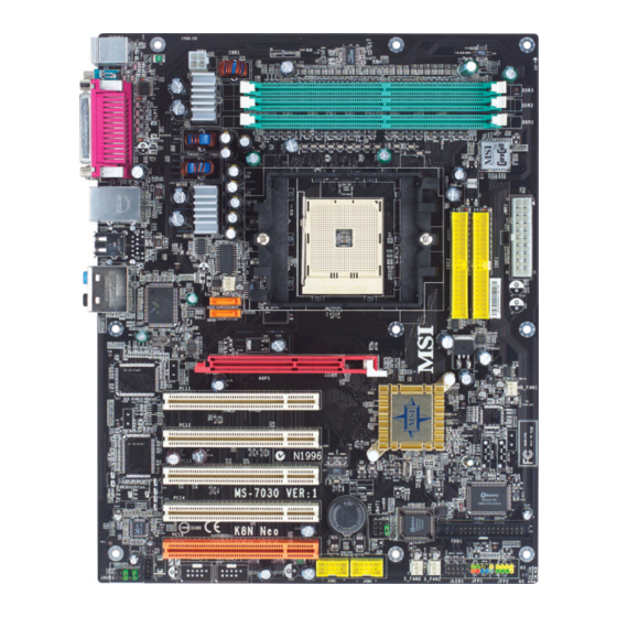
MS-7030 ATX Mainboard Mainboard Layout Top : mouse Bottom: keyboard DDR3 DDR2 Top : Parallel Port DDR1 Bottom: COM A 1394 Port SPDIF T: LAN jack B: USB ports B: USB ports Line-In Line-Out C_FAN1 M i c T:RS-Out M:CS-Out SATA3 (Optional) B:SPDIFOut SATA4 (Optional) -
Page 13: Hardware Setup
Hardware Setup Chapter 2. Hardware Setup Hardware Setup This chapter tells you how to install the CPU, memory modules, and expansion cards, as well as how to setup the jumpers on the mainboard. Also, it provides the instructions on connecting the periph- eral devices, such as the mouse, keyboard, etc. -
Page 14: Quick Components Guide
MS-7030 ATX Mainboard Quick Components Guide JPW1, p.2-9 DDR DIMMs, p.2-7 Back Panel IDE1/2, p.2-16 I/O, p.2-11 JWR1, p.2-9 C_FAN1, p.2-15 SATA3, SATA4, p.2-17 AGP1, p.2-24 NB_FAN1, p.2-15 SATA1, SATA2, p.2-17 JCASE1, PCI Slots 1~5, p.2-22 p.2-24 BATT FDD1, p.2-15 JAUD1, p.2-20 JFP2, p.2-18 JFP1, p.2-18... - Page 15 If you do not have the heat sink and cooling fan, contact your dealer to purchase and install them before turning on the computer. For the latest information about CPU, please visit http://www.msi.com.tw/ program/products/mainboard/mbd/pro_mbd_cpu_support.php. MSI Reminds You...
-
Page 16: Cpu Installation Procedures For Socket 754
MS-7030 ATX Mainboard CPU Installation Procedures for Socket 754 Please turn off the power and unplug the power cord before O pen Lever installing the CPU. Sl i d i n g 90 degree Pl a t e Pull the lever sideways away from the socket. -
Page 17: Installing Amd Athlon64 Cpu Cooler Set
Hardware Setup Installing AMD Athlon64 CPU Cooler Set When you are installing the CPU, make sure the CPU has a heat sink and a cooling fan attached on the top to prevent overheating. If you do not have the heat sink and cooling fan, contact your dealer to purchase and install them before turning on the computer. - Page 18 7. Locate the Fix Lever, Safety Hook and the Fixed Bolt. Lift up the in- tensive fixed lever. MSI Reminds You... While disconnecting the Safety Hook from the fixed bolt, it is necessary to keep an eye on Safety Hook...
-
Page 19: Installing Ddr Modules
Line Memory Module) modules and supports the memory size up to 3GB (for DDR266/ 333) / 2GB (for DDR400). You can install DDR266/333/400 modules on the DDR DIMM slots (DDR 1~3). For the updated supporting memory modules, please visit http://www.msi. com.tw/program/products/mainboard/mbd/pro_mbd_trp_list.php. DDR 3... - Page 20 MS-7030 ATX Mainboard Recommended Memory Combination List DIMM Slot Max Speed DDR1 DDR2 DDR3 DDR 400 DDR 400 DDR 400 DDR 400 DDR 400 DDR 400 DDR 400 DDR 400 DDR 400 DDR 400 DDR 400 DDR 400 DDR 400 DDR 400 DDR 400 DDR 400...
-
Page 21: Power Supply
JPW1 Pin Definition SIGNAL JPW1 MSI Reminds You... 1. These two connectors connect to the ATX power supply and have to work together to ensure stable operation of the mainboard. 2. Power supply of 300 watts (and above) is highly recommended for system stability. -
Page 22: Important Notification About Power Issue
MS-7030 ATX Mainboard Important Notification about Power Issue NForce chipset is very sensitive to ESD (Electrostatic Discharge), therefore this issue mostly happens while the users intensively swap memory modules under S5 (power-off) states, and the power code is plugged while installing modules. Due to several pins are very sensitive to ESD, so this kind of memory-replacement actions might cause chipset system unable to boot. -
Page 23: Back Panel
Hardware Setup Back Panel The back panel provides the following connectors: RS-Out L-In Parallel Mouse S/PDIF 1394 Port CS-Out COM A L-Out Keyboard USB Ports (optional) SPDIF Out Mouse/Keyboard Connector ® The mainboard provides a standard PS/2 mouse/keyboard mini DIN connector ®... -
Page 24: Serial Port Connector
MS-7030 ATX Mainboard Serial Port Connector The mainboard offers one 9-pin male DIN connector as the serial port. The port is a 16550A high speed communication port that sends/receives 16 bytes FIFOs. You can attach a serial mouse or other serial devices directly to the connector. Pin Definition 1 2 3 4 5 SIGNAL... -
Page 25: Audio Port Connectors
Hardware Setup LAN (RJ-45) Jack The mainboard provides 1 standard RJ-45 jack for connection to single Local Area Network (LAN). This Giga-bit LAN enables data to be transferred at 1000, 100 or 10Mbps. You can connect a network cable to this LAN jack. Giga-bit LAN Pin Definition SIGNAL DESCRIPTION... - Page 26 MS-7030 ATX Mainboard Parallel Port Connector: LPT1 The mainboard provides a 25-pin female centronic connector as LPT. A parallel port is a standard printer port that supports Enhanced Parallel Port (EPP) and Ex- tended Capabilities Parallel Port (ECP) mode. Pin Definition SIGNAL DESCRIPTION STROBE...
- Page 27 C_FAN1 S_FAN1 S_FAN2 NB_FAN1 MSI Reminds You... 1. Always consult the vendors for proper CPU cooling fan. 2. C_FAN1 supports the fan control. You can install Core Center utility that will automatically control the CPU fan speed according to the actual CPU temperature.
- Page 28 IDE2 (Secondary IDE Connector) IDE2 can also connect a Master and a Slave drive. MSI Reminds You... If you install two hard disks on cable, you must configure the second drive to Slave mode by setting its jumper. Refer to the hard disk documentation supplied by hard disk vendors for jumper setting instructions.
- Page 29 Take out the dust cover and connect to the hard disk devices Connect to serial ATA ports MSI Reminds You... Please do not fold the serial ATA cable in a 90-degree angle, which will cause the loss of data during the transmission. E-2-17...
-
Page 30: Front Panel Connectors
MS-7030 ATX Mainboard Front Panel Connectors: JFP1 & JFP2 The mainboard provides two front panel connectors for electrical connection ® to the front panel switches and LEDs. JFP1 is compliant with Intel Front Panel I/O Connectivity Design Guide. Power Power Speaker Switch JFP2... - Page 31 Hardware Setup D-Bracket™ 2 Connector: JLED1 (Optional) The mainboard comes with a JLED1 connector for you to connect to D-Bracket™ 2. D-Bracket™ 2 is a USB Bracket that supports both USB1.1 & 2.0 spec. It integrates four LEDs and allows users to identify system problem through 16 various combina- tions of LED signals.
- Page 32 Left channel audio signal to front panel AUD_RET_L Left channel audio signal return from front panel MSI Reminds You... If you don’t want to connect to the front audio header, pins 5 & 6, 9 & 10 have to be jumpered in order to have signal output directed to the rear audio ports.
- Page 33 Hardware Setup IrDA Infrared Module Header: JIR1 The connector allows you to connect to IrDA Infrared module. You must config- ure the setting through the BIOS setup to use the IR function. JIR1 is compliant with Intel ® Front Panel I/O Connectivity Design Guide. JIR1 Pin Definition Signal Signal...
- Page 34 MS-7030 ATX Mainboard Chassis Intrusion Switch Connector: JCASE1 This connector is connected to a 2-pin chassis switch. If the chassis is opened, the switch will be short. The system will record this status and show a warning message on the screen. To clear the warning, you must enter the BIOS utility and clear the record.
-
Page 35: Jumper
JBAT1 Keep Data Clear Data MSI Reminds You... You can clear CMOS by shorting 2-3 pin while the system is off. Then return to 1-2 pin position. Avoid clearing the CMOS while the system is on; it will damage the mainboard. -
Page 36: Pci Interrupt Request Routing
MS-7030 ATX Mainboard Slots The mainboard provides one AGP slot and five 32-bit PCI bus slots. AGP (Accelerated Graphics Port) Slot The AGP slot allows you to insert the AGP graphics card. AGP is an interface specification designed for the throughput demands of 3D graphics. It introduces a 66MHz, 32-bit channel for the graphics controller to directly access main memory. -
Page 37: Bios Setup
² An error message appears on the screen during system boot up, and requests you to run SETUP. ² You want to change the default settings for customized features. MSI Reminds You... 1. The items under each BIOS category described in this chapter are under continuous update for better system performance. -
Page 38: Entering Setup
MS-7030 ATX Mainboard Entering Setup Power on the computer and the system will start POST (Power On Self Test) process. When the message below appears on the screen, press <DEL> key to enter Setup. Press DEL to enter SETUP If the message disappears before you respond and you still wish to enter Setup, restart the system by turning it OFF and On or pressing the RESET button. -
Page 39: Control Keys
BIOS Setup Control Keys < > Move to the previous item < > Move to the next item < > Move to the item in the left hand < > Move to the item in the right hand <Enter> Select the item <Esc>... -
Page 40: The Main Menu
MS-7030 ATX Mainboard The Main Menu ® Once you enter Phoenix-Award BIOS CMOS Setup Utility, the Main Menu will appear on the screen. The Main Menu allows you to select from twelve setup functions and two exit choices. Use arrow keys to select among the items and press <Enter> to accept or enter the sub-menu. - Page 41 BIOS Setup Load Optimized Defaults Use this menu to load the BIOS values for the best system performance, but the system stability may be affected. Set Supervisor Password Use this menu to set Supervisor Password. Set User Password Use this menu to set User Password. Save &...
-
Page 42: Cell Menu
Cell Menu The items in Cell Menu includes some important settings of CPU, AGP, DRAM and overclocking functions. MSI Reminds You... Change these settings only if you are familiar with the chipset. Current CPU / DDR Clock These two items show the current clocks of CPU & DDR. Read-only. - Page 43 [Enabled], [Disabled]. Dynamic Overclocking Dynamic Overclocking Technology is the automatic overclocking function, included in the MSI ’ s newly developed CoreCell Technology. It is designed to detect the load balance of CPU while running programs, and to adjust the best CPU frequency automatically.
- Page 44 5th level of overclocking, increasing the CPU frequency by 9%. [Commander] 6th level of overclocking, increasing the CPU frequency by 11%. MSI Reminds You... Even though the Dynamic Overclocking Technology is more stable than manual overclocking, basically, it is still risky. We suggest user to make sure that your CPU can afford to overclocking regularly first.
- Page 45 AGP voltage is adjustable in the field, allowing you to increase the performance of your AGP display card when overclocking, but the stability may be affected. MSI Reminds You... The settings shown in different color in CPU Voltage, Memory Volt- age and AGP Voltage help to verify if your setting is proper for your system.
- Page 46 Introduction K8N Neo User’s Guide French F-1-1...
- Page 47 Carte M ère ATX MS-7030 F-1-2...
-
Page 48: Getting Started
Introduction Chap t er 1 . Ge tting Started Introduction Félicitation, vous venez d’ achter la carte mère ATX K8N Neo ® (MS-7030) v1.X. La K8N Neo est basée sur le chipset nVIDIA nForce™ 3 250Gb pour obtenir un système performant. Destiné aux ®... - Page 49 † Supporte 3 modules 184-pin DDR DIMM † Supporte jusqu’ à 3GB de mémoires (pour DDR333/266) / 2GB (Pour DDR400) . † Supporte DDR 400/333/266. (Pour une mise à jour sur les mémoires supportées, visitez http://www.msi.com.tw/ program/products/mainboard/mbd/pro_mbd_trp_list.php.) Slots † Un slot AGP (Accelerated Graphics Port) 1.5v 4X/8X †...
- Page 50 † Format ATX : 24.4 cm (L) x 30.5 cm (W) † 9 trous de montage MSI Vous Rappelle... 1. Please note that users cannot install OS, either WinME or Win98, in their SATA hard drive. Under these two OSs, SATA can only be used as a normal storage device.
- Page 51 Carte M ère ATX MS-7030 Schéma de la Carte Mère Top : mouse Bottom: keyboard DDR3 DDR2 Top : Parallel Port DDR1 Bottom: COM A 1394 Port SPDIF T: LAN jack B: USB ports B: USB ports Line-In Line-Out C_FAN1 M i c T:RS-Out M:CS-Out...
-
Page 52: Hardware Setup
Installation Matériel Chapter 2. Hardware Setup Installation Matériel Ce chapitre vous donne des indications sur l’installation du CPU, des modules de mémoire, les cartes d’extension, ainsi que sur la configuration des cavaliers de la carte mère. Vous retrouverez aussi des instructions pour la connexion de périphériques (souris, clavier ...). - Page 53 Carte Mère ATX MS-7030 Guide des Composants JPW1, p.2-9 DDR DIMMs, p.2-7 P a n n e a u IDE1/2, p.2-16 Arrière I/O, p.2-11 JWR1, p.2-9 C_FAN1, p.2-15 SATA3, SATA4, p.2-17 AGP1, p.2-24 NB_FAN1, p.2-15 SATA1, SATA2, p.2-17 JCASE1, Slots PCI 1~5, p.2-22 p.2-24 BATT...
- Page 54 Pourconnaître les dernières informations sur les CPU, veuillez visiter http:// www.msi.com.tw/program/products/mainboard/mbd/pro_mbd_cpu_support.php. MSI Vous Rappelle... Surchauffe Une surchauffe peut sérieusement endommager le CPU et le système, assurez vous toujours que le système de reffroidissement fonctionne correctement pour protéger le CPU d’une surchauffe...
- Page 55 Carte Mère ATX MS-7030 Procédure d’Installation du CPU - Socket 754 O pen Lever Sl i d i n g 90 degree Pl a t e Veuillez éteindre et débrancher votre PC avant l’installation du CPU. Tirez le levier vers le haut. G ol d arr ow Assurez-vous que celui-ci est bien en position ouverte maxi-...
- Page 56 Installation Matériel Installer le système de refroidissement du CPU AMD Athlon64 Quand vous installerez votre CPU, assurez vous que le CPU possède un système de reffroidissement pour prévenir les surchauffes. Si vous ne possédez pas de système de reffroidissement, contactez votre revendeur pour vous en procurer un et installez le avant d’allumer l’orcinateur.
- Page 57 7. Localisez le levier de fixation, et a c c r o c h e z l e b i e n s u r s o n encoche. MSI Vous Rappelle... Quand vous deconnecterez Relevez le levier de fixation.
- Page 58 Le clip en plastique situé de chaque côté du module va se fermer automatiquement. E n c o c h e Volt MSI Vous Rappelle... Les broches dorées ne sont plus visibles lorsque le module est correctement inséré dans le socket. F-2-7...
- Page 59 Carte Mère ATX MS-7030 Liste de Combinaison des Mémoires Slot DIMM Vitesse Max DDR1 DDR2 DDR3 DDR 400 DDR 400 DDR 400 DDR 400 DDR 400 DDR 400 DDR 400 DDR 400 DDR 400 DDR 400 DDR 400 DDR 400 DDR 400 DDR 400 DDR 400...
- Page 60 JWR1 JPW1 Pin Definition SIGNAL JPW1 MSI Vous Rappelle... 1. Ce deux connecteurs ATX doivent fonctionner ensemble pour as- surer la stabilité de la carte mère. 2. Une alimentation de 300Watt (et plus) est fortement recommandé pour la stabilité du système.
- Page 61 Carte Mère ATX MS-7030 Information Importante Relative à l’Alimentation Le chipset NForce est sensible aux ESD (Décharge Électrostatique), cependant l’electricité statique est ressentie plus particulièrement lorsque l’on remplace un module de mémoire alors que le PC est en mode S5 (power-off)et qu’il est encore relié à la prise du secteur.
- Page 62 Installation Matériel Panneau Arrière Le panneau arrière procure les connecteurs suivants : RS-Out L-In Parallèle Souris Réseau S/PDIF Port 1394 CS-Out COM A L-Out Clavier Ports USB (optionnel) SPDIF Out Connecteur Souris/Clavier ® La carte procure un connecteur Din standard pour souris PS/2 .
- Page 63 Carte Mère ATX MS-7030 Connecteur Port Série La carte mConnecteur possède un connecteur 9 broches male. C’est un port de communication 16550A qui envoie/reçcoit 16 bytes FIFOs. Vous pouvez y brancher une souris série ou n’importe quel autre appareils série. Pin Definition 1 2 3 4 5 SIGNAL...
- Page 64 Installation Matériel LAN (RJ-45) Jack La cartre mère possède en option un connecteur jack RJ-45 permettant de se connecter à un LAN (Local Area Network). Vous pouvez connecter un câble LAN sur ce jack. Giga-bit LAN Pin Definition SIGNAL DESCRIPTION Differential Pair 0+ Differential Pair 0- Differential Pair 1+...
- Page 65 Carte Mère ATX MS-7030 Connecteur Port Parallèle : LPT1 La carte procure un connecteur (25 broches femelle) pour LPT. Un port parallèle est un port imprimante standard supportant les modes EPP (Enhanced Prallel Port) et ECP (Extended Capabilities Parallel Port. Pin Definition SIGNAL DESCRIPTION...
- Page 66 Sensor C_FAN1 S_FAN1 S_FAN2 NB_FAN1 MSI Vous Rappelle... 1. Toujours consulter votre revendeur au sujet du radiateur + ventilateur. 2. Vous pouvez installer l’utilitaire PC Alert pour contrôler la température du CPU et la vitesse de rotation du ventilateur. ®...
- Page 67 IDE2 (Connecteur IDE Secondaire) Possibilité de connecter un disque en “maître” et un autre en “esclave” sur l’IDE2 MSI Vous Rappelle... Si vous installez 2 disques durs sur une même nappe, vous devez configurer le second disque en mode Slave (esclave) en bougeant un cavalier.
- Page 68 SIGNAL SATA2 SATA1 Câble Serial ATA Retirer le bouchon avant la connexion A connecter aux ports serial MSI Vous Rappelle... Ne pas tordre les câble serial ata avec un angle de 90° cela pourraît gêner la transmission des données F-2-17...
- Page 69 Carte Mère ATX MS-7030 Connecteurs Façade : JFP1 & JFP2 La carte offre deux connecteurs front panel permettant l’alimentation electrique ® de LED. JFP1 est compatible avec l’Intel Front Panel I/O Connectivity Design Guide. Power Power Speaker Switch JFP2 JFP1 Power Reset Switch...
- Page 70 Installation Matériel Connecteur D-Bracket™ 2 : JLED1 (Optionnel) La carte possède un connecteur JLED1 permettant d’identifier les problèmes et ce à l’aide de 16 combinaisons de couleurs. Pin Definition Signal DBG1 (high for green color) DBR1 (high for red color) DBG2 (high for green color) JLED1 DBR2 (high for red color)
- Page 71 Left channel audio signal to front panel AUD_RET_L Left channel audio signal return from front panel MSI Vous Rappelle... Si vous ne voulez pas connecter le front audio header, les broches 5 & 6, 9 & 10 doit être recouvertes avec un cavalierpour que le signal de sortie soit redirigé...
- Page 72 Installation Matériel Module IrDA (Infra rouge) : JIR1 Ce connecteur permet de la mise en place d’un module infra rouge. Vous devez configurer cette fonction dans le BIOIS afin de pouvoir l’utiliser. JIR1 est compatible avec l’Intel ® Front Panel I/O Connectivity Design Guide. JIR1 Pin Definition Signal Signal...
- Page 73 Carte Mère ATX MS-7030 Connecteur Chassis Intrusion : JCASE1 Ce connecteur est connécté à un switch à 2 broches sur le chassis. Si le chassis est ouvert, le switch en informera le système, qui enregistrera ce status et affichera un écran d’alerte. Pour effacer ce message d’alerte, vous devez entrer dans le BIOS et désactiver l’alerte.
- Page 74 E f f a c e r données données MSI Vous Rappelle... Vous pouvez effacer le CMOS en plaçant le cavalier sur les broche 2- 3, lorsque le système est éteint. Replacez ensuite le cavalier sur 1-2. N’effacez jamais le CMOS lorsque le système est allumé,cela endomagerait la carte mère.
- Page 75 Carte Mère ATX MS-7030 Slots La carte offre un slot AGP et cinq slots PCI 32-bit. Slot AGP (Accelerated Graphics Port) Le slot AGP permet la mise en placed ‘une carte graphique. L’interface AGP est destiné à répondre aux demandes 3D. Le slot supporte les cartes AGP 4 et 8x. Slot AGP Slot PCI (Peripheral Component Interconnect) Les slots PCI vous permettent d’ajouter des cartes d’extensions.
-
Page 76: Bios Setup
Setup du BIOS Chapter 3. BIOS Setup Setup du BIOS Ce chapitre procure des informations sur le programme de BIOS et vous permet de configurer le systcme pour une utilisation optimale. Vous devez entrer dans le setup lorsque : ² Une erreur apparaî... - Page 77 Carte M ère ATX MS-7030 Entrer dans le Setup Allumez votre ordinateur, le systcme lance le processus de POST (Power On Self Test). Quand le message ci-dessous apparaît r l’ écran, appuyez sur le bouton <DEL> pour entrer dans le setup. DEL:Setup F11:Boot Menu F12:Network boot...
- Page 78 Setup du BIOS Touches de Contrô le < Se déplacer au champ précédent. < Se déplacer au champ suivant. < Se déplacer au champ sur la gauche. < Se déplacer au champ sur la droit. <Enter> Séléctoinner le champ. <Esc> Quitter ou retourner au menu principal.
- Page 79 Carte M ère ATX MS-7030 Menu principale Une fois entré dans l’ AMIBIOS NEW SETUP UTILITY, le menu suivant apparaî t r l’ écran. Le menu principal offre 12 fonctions configurables ant duex choix de sortie. Utilisez les flcches pour vous déplacer r l’ intérieur du menu et appuyez sur <Enter> pour accéder au sous-menu.
- Page 80 Setup du BIOS Load Optimized Defaults Charge les paramètres optimum du BIOS sans affecter la stabilité du système. Set Supervisor Password Utilisez ce menu pour entrer un mot de passe Superviseur. Set User Password Utilisez ce menu pour entrer un mot de passe Utilisateur. Save &...
- Page 81 Cell Menu Vous pouvez dans ce menu gérer d’ importantes fonctions du CPU, AGP, DRAM et d’ overclocking. MSI vous rapelle... Ne changer ces paramètres que si vous maî trisez bien ce chipset. Current CPU / DDR Clock Vitesse d’ horloge des CPU & DDR. Lecture seule.
- Page 82 Dynamic Overclocking Le DOT (Dynamic Overclocking Technology) est une fonction overclocking automatique inclut dans la nouvelle technologie CoreCell développée par MSI . Déstiné r détecter la charge de travail du CPU lors de l’ utilisation de programmes, le DOT permet d’...
- Page 83 [Commander] 6ème niveau d’ overclocking, augmentant la fréquence CPU de 11%. MSI Vous Rappelle... Meme si le DOT est plus stable que l’ overclocking manuel, cela reste risqué. Nous vous suggérons de faire un overclocking progressif, et du juger r la vue des résultats si vous devez désactiver le DOT ou choisir un niveau plus ou moins elevé...
- Page 84 Le voltage AGP est modifiable, ce qui vous permet d’ augmenter la performance la carte graphique lors de l’ overclocking, mais la stabilité n’ est pas assurée. MSI Vous Rappelle... Les paramètres de couleurs différentes pour CPU Voltage, Memory Voltage et AGP Voltage vous aident à vérifier si les paramètres pour votre système sont correctes.
- Page 85 Benutzerhandbuch K8N Neo User’s Guide German...
- Page 86 MS-7030 ATX Mainboard...
- Page 87 Benutzerhandbuch Benutzerhandbuch Danke für die Wahl des K8N Neo (MS-7030) v1.X ATX ® Mainboards. Das K8N Neo Mainboard basiert auf dem nVIDIA nForce™ 3 250Gb Chipsatz für optimale Systemeffizienz. Entwickelt, um den fortgeschrittenen AMD ® Athlon 64 Prozessor eine optimale Plattform bereitzustellen, bietet das K8N Neo Mainboard hohe Perfomrance und eine proffessionelle Umgebung.
- Page 88 MS-7030 ATX Mainboard Mainboard Spezifikationen Unterstützt Sockel-754 für AMD K8 Athlon™ Prozessoren bis 3400 (Die neuesten Informationen zu unterstützten Prozessoren finden Sie auf der Webseite: http://www.msi.com.tw/program/products/mainboard/mbd/pro_mbd_cpu_support. php) Chipsatz nVIDIA nForce3 250Gb - Unterstützt K8 Athlon64 Prozessor S-754, 800MHz Hypertransport Schnittstelle.
- Page 89 Befestigung und Größe ATX Form Factor: 24.4 cm (T) x 30.5 cm (B) 9 Befestigungslöcher MSI erinnert Sie... 1. Bitte berücksichtigen Sie, dass Sie Windows ME oder Windows 98, nicht auf einer SATA Festplatte installieren können. Bei diesen Betriebssystemen könne SATA-Laufwerke ausschliesslich für Daten und Anwendungen, nicht aber für das Betriebsssystem selbst...
- Page 90 MS-7030 ATX Mainboard Mainboard Layout Top : mouse Bottom : keyboard DDR3 DDR2 Top : Parallel Port DDR1 Bottom : COM A 1394 Port SPDIF T: LAN jack B: USB ports B: USB ports Lin e-In Lin e-Out C_FAN1 T:RS-O ut M:CS-Out SATA3 (Optional) B:SPDIFOut...
- Page 91 Benutzerhandbuch ATX 20-Pin Netzteilanschluss: JWR1Hier wird der 20 Pin-Stecker des Netzteils angeschlossen ATX 12V Netzteilanschluss: JPW1 Dieser 12V Netzteilanschluss dient zur Stromversorgung der CPU. Bitte diesen Stecker anschliessen! Floppylaufwerk-Anschluss: FDD1 Das Mainboard stellt diesen Anschluss für Standard Floppylaufwerke mit 360K, 720K, 1.2M, 1.44M und 2.88M zur Verfügung.
- Page 92 System zu erfüllen. Wenn Sie Erweiterungskarten hinzufügen oder entfernen, stellen Sie sicher, dass der PC ausgeschaltet und von Strombnetz getrennt ist. Das gillt auch für AGP! Der orangene PCI Steckplatz (PCI5) funktioniert auch als Kommunikations-Steckplatz für spezielle WiFi-Karten von MSI.
- Page 93 Kühler für die CPU haben und aufsetzen, um die CPU vor Überhitzung zu schützen. Wenn Sie noch keinen passenden Kühler haben, kontaktieren Sie Ihren Händler für weitere Hilfe. Schalten Sie den PC niemals ohne CPU-Kühler ein!. Für die neuesten Informationen zur Prozessorunterstützung besuchen Sie die folgende Webseite:http://www.msi.com.tw/program/products/mainboard/mbd/ pro_mbd_cpu_support.php. Speichertakt/CPU FSB Unterstützungs-Matrix Memory...
- Page 94 Kühlers. 4. Schliessen Sie das Stzromkabel des lüfters an den CPU-Lüfter-Anschluss des Mainboards an.. Apply some MSI erinnert Sie... Bitte verwenden Sie unbedingt Wärmeleitpaste zwischen dem Prozessor und dem Kühler, dmait die Wärme effektif von der CPU abgefühert werden kann.
- Page 95 (mit DDR266/333) / 2GB (mit DDR400). Sie können DDR266/333/400 Module in jeder Reihenfolge auf den Steckplätzen 1~3 einsetzen. Für neueste Informationen zur Speicherkompatibilität besuchen Sie die Webseite http://www.msi.com.tw/program/products/mainboard/mbd/pro_mbd_trp_list.php. DDR Bestückungsregeln Sie müssen wenigstens ein DIMM Modul einsetzen, damit der PC gunktioniert. Jedes DIMM-Modukl kann bis zu 1GB groß...
- Page 96 MS-7030 ATX Mainboard BIOS Setup Schalten Sie den PC ein, und sofort wird der POST (Power On Self Test) gestartet. Wenn dieser abgeschlossen ist, erscheint die folgende Meldung: DEL: Setup F11: Boot Menu F12: Network boot TAB: Logo F10: Flash Recovery Drücken Sie nun die Taste ENTF um in das Setup zu gelangen.Wenn die Meldung verschwindet, bevor Sie die Taste drücken konnten, starten Sie den PC erneut per Reset-Knopf, Warmstart (STRRG+ALT+Entf) gleichzeitig drücken...
Need help?
Do you have a question about the K8N Neo Platinum and is the answer not in the manual?
Questions and answers