
Related Manuals for Lowrance X50 DS


Summary of Contents for Lowrance X50 DS
- Page 1 Pub. 988-0151-431 www.lowrance.com Fish-Finding Sonar Installation and Operation Instructions...
- Page 2 Lowrance Electronics, Inc. ® Lowrance Electronics may find it necessary to change or end our policies, regulations, and special offers at any time. We reserve the right to do so without notice. All features and specifications subject to change without notice.
-
Page 3: Table Of Contents
Table of Contents Introduction..................1 Capabilities and Specifications: X50 DS ..........1 How Sonar Works.................2 Preparations ..................3 Installation ...................4 Recommended Tools and supplies...........4 Selecting a Transducer Location .............5 How low should you go? ..............6 Shoot-Thru-Hull vs. Transom Mounting ........7 Transom Transducer Assembly and Mounting ......7 Trolling Motor Bracket Installation..........12... - Page 4 Deep Alarm..................40 Battery Alarm..................40 Noise Rejection and ASP ..............41 Depth Display..................43 Temperature Display .................43 Voltage ....................44 Backlight.....................44 Contrast ....................44 Simulator ....................44 Set Language ..................45 Software Information.................45 Reset Options..................45 Troubleshooting................46...
-
Page 5: Introduction
( ) key. To get started with your Lowrance sonar, first read the installation sec- tion. It contains instructions for mounting the sonar unit, the trans- ducer and any optional accessories, such as a speed sensor. -
Page 6: How Sonar Works
Transmitter:....1,500 watts peak-to-peak power (typical); 188 watts RMS power (typical). Sonar sounding depth capability:....1,000 feet (305 meters). Actual capability de- pends on transducer configuration and in- stallation, bottom composition and water con- ditions. All sonar units typically read deeper in fresh water than in salt water. Depth display: ....Continuous digital readout. -
Page 7: Preparations
The receiver amplifies this return signal, or echo, and sends it to the display, where an image of the object appears on the scrolling sonar chart. The sonar's microprocessor calculates the time lapse between the transmitted signal and echo return to determine the distance to the object. -
Page 8: Installation
3. Determine the location of your battery or other power connection, along with the power cable route. 4. Install the transducer and route the transducer cable to the sonar unit. 5. Route the power cable from the unit's location to an appropriate power source and connect it there. -
Page 9: Selecting A Transducer Location
Single-frequency transom installations Tools include: two adjustable wrenches, drill, #29 (0.136") drill bit, flat- head screwdriver (for mounting screws and their pilot holes). Supplies: none. Single-frequency trolling motor installations Tools: two adjustable wrenches, flat-head screwdriver. Supplies: plastic cable ties. Shoot-through hull installations Tools: these will vary depending on your hull's composition. -
Page 10: How Low Should You Go
5. If possible, route the transducer cable away from other wiring on the boat. Electrical noise from engine wiring, bilge pumps and aerators can be displayed on the sonar's screen. Use caution when routing the transducer cable around these wires. CAUTION: Clamp the trans- ducer cable to transom near the transducer. -
Page 11: Shoot-Thru-Hull Vs. Transom Mounting
If you cruise or fish around lots of structure and cover, your transducer may be frequently kicking up from object strikes. If you wish, you may move the transducer a little higher for more protection. There are two extremes you should avoid. Never let the edge of the mounting bracket extend below the bottom of the hull. - Page 12 Place each ratchet into the bracket with the letter "A" aligned with the dot stamped into the metal bracket. This position sets the transducer's coarse angle adjustment for a 14° transom. Most outboard and stern-drive transoms have a 14° angle. Align plastic ratchets in bracket.
- Page 13 3. Assembling the transducer. Once you determine the correct posi- tion for the ratchets, assemble the transducer as shown in the following figure. Don't tighten the lock nut at this time. Metal washer Rubber washers Metal washer Bolt Assemble transducer and bracket. 4.
- Page 14 Transom Transom Position transducer mount on transom and mark mounting holes. Side view shown at left and seen from above at right. 5. Attaching transducer to transom. Remove the transducer from the bracket and re-assemble it with the cable passing through the bracket over the bolt as shown in the following figures.
- Page 15 Bottom hull Deep-"vee" hull Flat-bottom hull Align transducer centerline with hull bottom and attach to transom. 6. Route the transducer cable through or over the transom to the sonar unit. Make sure you leave some slack in the cable at the transducer.
-
Page 16: Trolling Motor Bracket Installation
Trolling Motor Bracket Installation 1. Attach the optional TMB-S bracket to the transducer as shown in the following figure, using the hardware supplied with the transducer. (Note: The internal tooth washer is supplied with the TMB-S.) TMB-S bracket Internal tooth washer Bolt Flat washer Attach motor mounting bracket to transducer. -
Page 17: Transducer Orientation And Fish Arches
Transducer Orientation and Fish Arches If you do not get good fish arches on your display, it could be because the transducer is not parallel with the ground when the boat is at rest in the water or at slow trolling speeds. Partial fish arches Transducer aimed Transducer aimed... - Page 18 ers. The sonar signal must pass through solid fiberglass. A successful transducer installation can be made on hulls with flotation materials (such as plywood, balsa wood or foam) between layers of fiberglass if the material is removed from the chosen area. See the figure below. WARNING: Do not remove any material from your inner hull unless you know the hull's composition.
-
Page 19: Testing Determines Best Location
Testing Determines Best Location Ideally, the shoot-thru transducer should be installed as close to the transom as possible, close to the centerline. This will give you the best performance during high speed maneuvers. 1. Anchor the boat in about 30 feet of water. Add a little water to the sump of the boat. -
Page 20: Shoot-Thru-Hull Installation
hull. This is especially true if you have to turn sensitivity all the way up to get a decent bottom signal. 4. Most people can get good results by following steps 1 through 3, so this step is optional. If you want to make an extra effort to be absolutely sure that your selected location will work under all conditions, make a test run with the boat on plane and observe the bottom signal. -
Page 21: Power Connections (Permanent Mount Only)
2. The epoxy consists of the epoxy itself and a hardener. Remove the two compounds from the package and place them on the paper plate. Thoroughly stir the two compounds together until the mixture has a uniform color and consistency. Do not mix too fast or bubbles will form in the epoxy. -
Page 22: Mounting The Sonar Unit: In-Dash, Bracket Or Portable
Black wire 12 volt battery Power connections for the X50 DS sonar unit (direct battery connection shown). If possible, keep the power cable away from other boat wiring, espe- cially the engine's wires. This will provide the best isolation from elec- trical noise. -
Page 23: Bracket Installation
[2.77] Front view (left) and side view (right) showing dimensions of the X50 DS when mounted on quick release bracket. Drill a 1" (25.4 mm) hole in the dash for the power/transducer and ac- cessory cables. The best location for this hole is immediately under the gimbal bracket location. - Page 24 Screw hole Power/transducer cable Cable slot X50 DS quick release mounting bracket. Slots in the base allow routing the cable from beneath the mount. Attach the unit to the bracket by first connecting the power/transducer and accessory cables. Then, hold the sonar unit vertically and slide it onto the bracket from above.
-
Page 25: Portable Sonar Installation
You can use your X50 DS sonar unit on your boat or take it to the dock, on a float tube, on an ice fishing trip or use it as a second sonar in a friend's boat. -
Page 26: Installing The Batteries
To use a portable power pack, you install the batteries and then attach the sonar unit to the power pack's bracket. Plug in the power/transducer cable and you're ready to fish. The PPP-12 has a quick-release mounting bracket built into the case. Installing the Batteries Open the case and lay it flat. -
Page 27: Portable Transducer Assembly
Ratchet To mount the sonar, slide the unit onto the bracket from above (left). To adjust the view, press and release spring-loaded ratchets while tilt- ing the unit (right). To adjust the viewing angle, pinch the quick-release mount's ratchets with one hand, then tilt the unit with your other hand. Release the ratchets and the unit locks into the new position. - Page 28 Make sure there is one washer on each side of the transducer, inside the bracket. Slide the other washer over the end of the bolt and screw on the nut. Screw the suction cup onto the bracket using the supplied screw and flat washer.
-
Page 29: Portable Transducer Storage
Hull Portable transducer installed on boat transom. Portable Transducer Storage There is room inside the power pack for the portable transducer. When you're finished fishing, tilt the sonar down to the storage position. Open the case and lay it flat. Unplug the power connector from the battery compartment socket. - Page 30 Notes...
-
Page 31: Operation
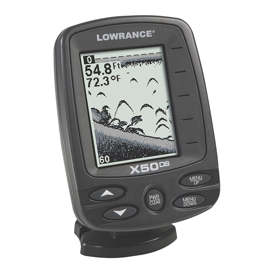
The unit sounds a tone when you press any key. This tells you the unit has accepted a command. Numbers in the figure correspond to key ex- planations below: Lowrance X50 DS. 1. PWR/CLEAR In this manual, the Power/Clear key is referred to as . -
Page 32: Memory
↓ (DOWN) ↑ (UP) this manual. You will use these keys to adjust most features and functions on the X50 DS. Memory This unit has permanent memory that saves the following user settings when power is turned off: Units of Measure, Temp Size, Depth Size, Fish I.D. -
Page 33: Display
Display The lights will flash for about 10 seconds when the unit is turned on. The backlight menu will appear on the screen. Use the keys to ARROW turn the backlight on or off. Press to clear the menu from the screen. -
Page 34: Depth Range
Digital depth Surface clutter Water Temp Bait fish Structure or cover Bottom signal Fish arches Depth range at bottom of Grayline depth scale Full Chart page, showing digital depth (above) and temp (below). The Fish I.D. feature is turned off. Depth Range When turned on, the unit automatically adjusts the depth range ac- cording to water conditions. -
Page 35: Zoom
Zoom The zoom feature enlarges all images on the screen by doubling the size of the echoes (a 2X zoom). For example, if the current auto depth range is 0 to 60 feet, Zoom will show an enlarged view of the water column from 30 feet to 60 feet, always keeping the bottom in view. -
Page 36: Sensitivity
Enlarged fish arches Zoom Range menu with the 40-80 foot zoom selected. You can select from these zoom size ranges: 0-10, 5-15, 10-20, 15-30, 20- 40, 30-60, 40-80, 50-100, 75-150, 100-200, 150-300, 200-400, 300-600, 400-800, 500-1000, 750-1500 and 1000-2000. Sensitivity Sensitivity adjusts the way echoes will be displayed on the screen. - Page 37 To adjust sensitivity in Auto Mode: Repeatedly press until the menu appears. Make sure sen- MENU ENSITIVITY sitivity is set to Auto, then press to access the sensitivity MENU UP scroll bar. Press to increase the sensitivity, to decrease it. When it is set ↑...
-
Page 38: Grayline
® Grayline Grayline lets you distinguish between strong and weak echoes. It al- lows you to tell the difference between a hard and soft bottom. For ex- ample, a soft, muddy or weedy bottom returns a weaker signal which is shown with a narrow line or no gray line at all. -
Page 39: Chart Speed
Wider Thin or no Grayline Grayline A small amount of Grayline indicates a soft bottom (left), probably sand or mud. More Grayline indicates a harder, rocky bottom (right). Press to increase Grayline, to decrease it. Echoes scrolling on the ↑... -
Page 40: Frequency
sonar signal cone, the image appears on the screen as a long line in- stead of a fish arch. Reducing the chart speed may result in a shorter line that more closely resembles a regular fish return. To adjust Chart Speed, repeatedly press until the MENU HART... - Page 41 The Fish I.D. feature displays symbols on the screen in place of the ac- tual fish echoes. There are three symbol sizes: small, medium and large. These show the relative size between targets. In other words, it displays a small fish symbol when it thinks a target is a small fish, a medium fish symbol on a larger target and so forth.
-
Page 42: Fishtrack
Fish I.D. can also be useful when you want to screen out some of the so- nar detail gathered by your unit. For example, it can help cut through the clutter of suspended bubbles caused by wave action or boat wakes. To turn Fish I.D. -
Page 43: Depth Alarms
Fish Alarm menu. Depth Alarms The depth alarms are triggered only by the bottom signal. No other echoes will activate these alarms. The depth alarms consist of a shal- low and a deep alarm. The shallow alarm sounds an alarm tone when the bottom goes shallower than the alarm's setting. -
Page 44: Deep Alarm
any of the previously entered numbers, press . Press MENU UP return to the Shallow Alarm menu. Use to select , which will turn ↑ on the alarm, then press to clear the menu. When the bottom depth becomes more shallow than the alarm’s setting, an alarm will sound and a message will appear on the screen. -
Page 45: Noise Rejection And Asp
Battery Alarm menu (left). Low Battery Alarm Value (right). Press the . The Low Battery Alarm Value dialog box will ↓ ALUE appear. Input a voltage value between 7 and 18 volts. Use the keys ↑ ↓ to enter the first number in the dialog box, then press MENU DOWN move to the next digit. - Page 46 Noise Rejection menu. The ASP noise rejection feature is especially useful because, typically, it lets you operate the boat at all speeds without adjusting the sensi- tivity or other controls. The ASP feature has three settings — Off, Low and High. When first turned on, noise rejection is set on low.
-
Page 47: Depth Display
Depth Display Depth may be displayed on the screen in a small, medium or large size or can be turned off completely. To display Depth: Repeatedly press until the menu appears. Use to select ↑ ↓ MENU EPTH the size of the depth display. Press to clear the menu. -
Page 48: Voltage
Voltage The Voltage menu allows you to display battery voltage on the screen in a small or medium size or can be turned off completely. To display battery voltage: Repeatedly press until the menu appears. Use to se- ↑ ↓ MENU OLTAGE lect the size of the voltage display. -
Page 49: Set Language
Simulator menu (left). Languages menu (right). To use the simulator, repeatedly press until the menu MENU IMULATOR appears. Press to turn it on and press to clear the menu. Repeat ↑ the steps above to turn it off. The simulator automatically will be turned off when you power off the unit. -
Page 50: Troubleshooting
Troubleshooting If your unit is not working, or if you need technical help, please use the following troubleshooting section before contacting the factory cus- tomer service department. It may save you the trouble of returning your unit for repair. For contact information, refer to the last page, just inside the back cover of this manual. - Page 51 3. The water may be deeper than the sonar's ability to find the bottom. If the sonar can't find the bottom signal while it's in the automatic mode, the digital sonar display will flash continuously. It may change the range to limits far greater than the water you are in.
- Page 52 vere cases, it can completely cover the screen with black dots, or cause the unit operate erratically, or not at all. To eliminate or minimize the effects of electrical noise, first try to de- termine the cause. With the boat at rest in the water, the first thing you should do is turn all electrical equipment on the boat off.
- Page 53 LOWRANCE ELECTRONICS FULL ONE-YEAR WARRANTY "We," "our," or "us" refers to LOWRANCE ELECTRONICS, a division of LEI, the manu- facturer of this product. "You" or "your" refers to the first person who purchases this product as a consumer item for personal, family, or household use.
-
Page 54: How To Obtain Service
800-324-1354 8 a.m. to 5 p.m. Central Standard Time, M-F Lowrance Electronics may find it necessary to change or end our ship- ping policies, regulations, and special offers at any time. We reserve the right to do so without notice. -
Page 55: Accessory Ordering Information
Accessory Ordering Information for all countries To order Lowrance GPS accessories such as computer cables or MMC cards, please contact: 1) Your local marine dealer or consumer electronics store. Most quality dealers that handle marine electronic equipment or other consumer electronics should be able to assist you with these items. - Page 56 Visit our web site: Lowrance Pub. 988-0151-431 © Copyright 2006 All Rights Reserved Printed in USA 032106 Lowrance Electronics, Inc.
Need help?
Do you have a question about the X50 DS and is the answer not in the manual?
Questions and answers