
Related Manuals for Lowrance X51


Summary of Contents for Lowrance X51
- Page 1 Pub. 988-0105-951 www.lowrance.com X51 and X58DF Fish-finding & Depth Sounding Sonars Installation and Operation Instructions...
- Page 2 Lowrance Electronics, Inc. Marine-Tex is a trademark of Illinois Tool Works Inc. Lowrance Electronics may find it necessary to change or end our policies, regulations, and special offers at any time. We reserve the right to do so without notice. All features and specifications subject to change without notice.
-
Page 3: Table Of Contents
Introduction ... 1 Capabilities and Specifications: X51 and X58DF... 1 Installation... 2 Transducer Installation... 2 Recommended Tools and Supplies ... 3 Selecting a Transducer Location ... 3 Shoot-Thru-Hull vs. Transom Mounting ... 5 Transom Transducer Assembly and Mounting ... 5 Trolling Motor Installation (Single-Frequency only) ... - Page 4 System Setup ... 44 Backlights... 44 Display Contrast ... 44 Depth Units of Measure... 45 Temperature Units of Measure ... 46 Speed and Distance Log Units of Measure ... 46 Reset Distance Log... 47 Preset Unit (Reset All Options)... 47 System Info...
-
Page 5: Introduction
( However, if you want to fine-tune your unit, press the The X51 and X58DF have several powerful features you can control by scrolling through easy-to-use menus with the arrow and menu keys. -
Page 6: Installation
These instructions cover Sonar comes packed with the X58DF. It has 35°/12° cone angles. Single frequency models for X51 with a 20° cone angle are sold separately. Both models offer a wide fish detection area of up to 60º... -
Page 7: Recommended Tools And Supplies
Remember, the transducer installation is the most critical part of a sonar installation. Recommended Tools and supplies If you prefer the option of routing the cable through the transom, you will need a 1"... - Page 8 If the transducer is not placed in a smooth flow of water, interference caused by bubbles and turbulence will show on the sonar's display in the form of random lines or dots whenever the boat is moving.
-
Page 9: Shoot-Thru-Hull Vs. Transom Mounting
Transducer centerline Align transducer centerline with hull bottom. However, there are times when you may need to adjust the transducer slightly higher or lower. (The slots in the mounting brackets allow you to loosen the screws and slide the transducer up or down.) If you fre- quently lose bottom signal lock while running at high speed, the trans- ducer may be coming out of the water as you cross waves or wakes. - Page 10 The following instructions sometimes vary depending on the mounting bracket that came with your transducer. Single frequency Skimmers come with a one-piece stainless steel bracket, while dual frequency Skimmers come with a two-piece plastic mounting bracket. Use the set of instructions that fits your model.
- Page 11 Transducer Transducer bracket Ratchet Ratchet Add ratchets to bracket and transducer. 2. Aligning the transducer on the transom. A. One-piece bracket: Slide the transducer between the two ratch- ets. Temporarily slide the bolt though the transducer assembly and hold it against the transom. Looking at the transducer from the side, check to see if it will adjust so that its face is parallel to the ground.
- Page 12 B. Two-piece bracket: Assemble the transducer and bracket as shown in the following figure. Temporarily slide the bolt though the transducer assembly but don't tighten the nut at this time. Hold the assembled transducer and bracket against the transom. Looking at the transducer from the side, check to see if it will adjust so that its face is parallel to the ground.
- Page 13 B. Two-piece bracket: Once you determine the correct position for the ratchets, assemble the transducer as shown in the figure in step 2B. Don't tighten the lock nut at this time. 4. Drilling mounting holes. Hold the transducer and bracket assembly against the transom. The transducer should be roughly parallel to the ground.
- Page 14 Electrical noise from the engine's wiring, bilge pumps, VHF radio wires and cables, and aerators can be picked up by the sonar. Use cau- tion when routing the transducer cable around these wires.
-
Page 15: Trolling Motor Installation (Single-Frequency Only)
(not included) to attach the transducer cable to the troll- ing motor shaft. Make sure there is enough slack in the cable for the motor to turn freely. Route the cable to the sonar unit and the trans- ducer is ready for use. -
Page 16: Transducer Orientation And Fish Arches
The transducer installation inside a fiberglass hull must be in an area that does not have air bubbles in the resin or separated fiberglass lay- ers. The sonar signal must pass through solid fiberglass. A successful Partial fish arches Proper transducer angle... - Page 17 Next, take the transducer out of the water and place it in the water in the sump of the boat. Observe the sonar signal to see if there is a no- ticeable decrease in sensitivity. The second bottom signal may disap- pear and the bottom signal may decrease in intensity.
- Page 18 cation that shot through the hull the best and follow the instructions on the following pages for a shoot-thru-hull mounting. Transducer location (high speed) Shoot-thru-hull transducer locations for high speed or trolling speed operation. Shoot-thru-hull Installation 1. Make sure the area is clean, dry and free of oil or grease, then sand both the inside surface of the hull and the face of the transducer with 100 grit sandpaper.
-
Page 19: Speed/Temperature Sensors
Speed/Temperature Sensors The X51 and X58DF can accept as many as two temperature sensors, which can be used to monitor the temperature of surface water, a live well or some other location. These units can also accept an optional speed sensor for showing speed and distance traveled. - Page 20 X51 or X58DF with external speed sensor. A temperature sensor is built into the transducer. MY-4X Cable X51 using a transducer without built-in temperature sensor. In this example, an external temperature sensor is used. X51 or X58DF rear view X51 or X58DF...
-
Page 21: Speed Sensor Installation
MY-4X Cable X51 or X58DF with external combination speed and temperature sensor. Speed Sensor Installation Though only the X58DF comes packed with a speed sensor, both units are capable of displaying speed and distance traveled. If you wish to purchase an optional additional sensor for your unit, refer to the acces- sory ordering information inside the back cover of this manual. -
Page 22: Power Connections
This will help ensure a smooth water flow. Route the sensor's cable through or over the transom to the sonar unit. If you need to drill a hole in the transom to pass the connector through, the required hole size is 7/8". -
Page 23: Mounting The Sonar Unit: In-Dash, Bracket Or Portable
To unit Power connections for the X51 and X58DF sonar unit. If possible, keep the power cable away from other boat wiring, espe- cially the engine's wires. This will provide the best isolation from elec- trical noise. If the cable is not long enough, splice #18 gauge wire onto it. -
Page 24: Bracket Installation
Cut on line R 6.35 [0.25] In-dash mounting template for X51 and X58DF sonars, showing dimen- sions. NOTE: The figure above is not printed to scale. A scaled template is available for free download from our web site, www.lowrance.com. Bracket Installation Mount the unit in any convenient location, provided there is clearance when it’s tilted for the best viewing angle. -
Page 25: Portable Sonar Installation
[5.20] Front view (left) and side view (right) showing dimensions of X51 and X58DF sonar unit when mounted on gimbal bracket. If you wish, you can fill in the hole around the cables with a good ma- rine caulking compound. (Some marine dealers stock cable hole covers to conceal the opening.) No matter what type of installation you prefer,... - Page 26 You can use your X51 or X58DF on your boat or take it to the dock, on a float tube, on an ice fishing trip or use it as a second sonar in a friend's boat. The PPP-10 Portable Power Pack can be used with eight "D" cell alkaline batteries (not included) or an optional sealed, rechargeable battery.
-
Page 27: Operation And Features
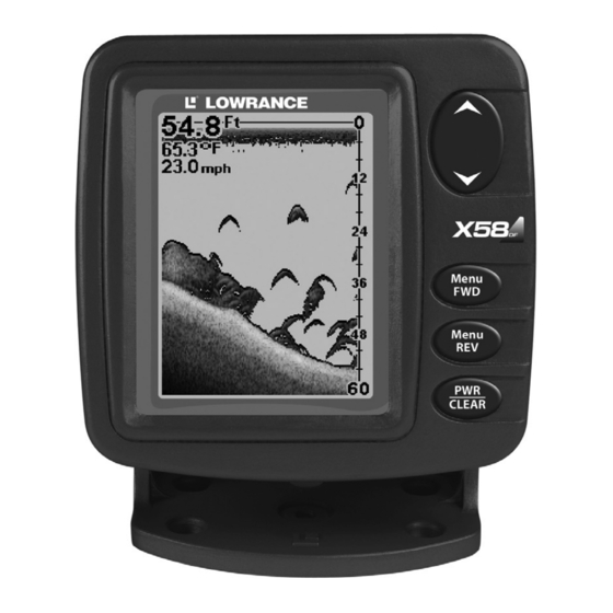
The unit sounds a tone when you press any key. This tells you the unit has accepted a command. Numbers in the photo correspond to key ex- planations below: Lowrance X58DF Sonar, front view, showing screen and keyboard. 1. PWR/CLEAR (power and clear) This key appears in the manual text simply as turn the unit on and off. -
Page 28: Up And Down Arrows
. Use DOWN ARROW UP ARROW these keys to adjust virtually every feature and function on the sonar unit. MEMORY This unit has permanent memory that saves all user settings, even when power is removed. It does not require, nor does it use an internal backup battery, so you never have to worry about replacement batteries. -
Page 29: Display - Opening Screen
If you don't want to wait, press the screen. When the sonar unit is first turned on and the backlight menu disap- pears, the display screen shows the Full Chart Page, or mode. The Fish I.D. feature is off. The depth range shows on the depth scale on the right side of the screen. -
Page 30: Screen Display Modes Or Pages
Chart is stopped at right, and "Stopped" warning message appears. SCREEN DISPLAY MODES or PAGES The X51 has four screen display modes, or "Pages:" Full Chart page, Split Chart page, Large Digital page and Flasher page. The X58DF also has a Dual Frequency page. -
Page 31: Split Chart
The line at the top of the screen represents the surface. The bottom depth (as determined by the digital sonar) shows in the upper left corner. If your speed sensor is con- nected, digital displays for speed and temperature will also be shown. -
Page 32: Dual-Frequency Split Chart (X58Df Only)
DUAL-FREQUENCY SPLIT CHART (X58DF only) This page shows sonar data from the 50 kHz transducer element on the left side of the screen and data from the 200 kHz transducer on the right side. All other functions and features are the same as the Full Chart page. -
Page 33: Lrg Digital (Large Digital)
A speed sensor is included with the X58DF. FLASHER The Flasher page represents a flasher style sonar. A circular dial shows all returning echoes at a high screen refresh rate. It uses the Grayline feature to show weaker targets as shades of gray. The bottom depth is also shown as a digital display in the center of the circle, while tem- perature and speed are shown at the bottom. -
Page 34: Range
RANGE When turned on for the first time, the unit automatically adjusts the depth range according to water conditions. It always keeps the bottom displayed in the lower portion of the screen. You can over-ride the automatic range control and manually select a range. To do this, press MENU keys to select the desired range. -
Page 35: Zoom
To set upper and lower limits, press pears. Press DOWN ARROW open the Upper Limit menu. Use the arrow keys to select the upper limit. In the example above, we have selected 10 feet. With the upper limit set, press the arrow keys to select the lower limit. - Page 36 NOTE: Using the Zoom command while in auto Range mode will always enlarge the echoes near the bottom, because auto Range always keeps the bottom displayed in the lower portion of the screen. When you Zoom in manual Range mode, echoes are enlarged near the middle of the displayed range.
-
Page 37: Sensitivity
SENSITIVITY Sensitivity controls the unit's ability to pick up echoes. If you want to see more detail, try increasing the sensitivity, a little at a time. There are situations when too much clutter appears on the screen. Decreasing the sensitivity can reduce the clutter and show the strongest fish ech- oes, if fish are present. - Page 38 you from turning sensitivity down too low to allow automatic bottom tracking. When you change the setting with auto turned on, the unit will continue to track the bottom and make minor adjustments to the sensi- tivity level, with a bias toward the setting you selected. Adjusting sensitivity in Manual Sensitivity Mode is similar to driving a car without cruise control —...
-
Page 39: Grayline
Since Grayline shows the difference between strong and weak signals, adjusting the sensitivity may also require a different Grayline level. The level chosen by the sonar unit at power on is usually adequate for most conditions. Experiment with your unit to find the Grayline setting that's best for you. -
Page 40: Fish I.d
At left, underwater scene in normal fish arch mode. Right, Fish I.D. Fish I.D. is an easier way for a sonar novice to recognize a fishy signal return when he sees it. However, locating fish by symbol only has some limitations. -
Page 41: Fishtrack
Does that mean Fish I.D. is broken? No — the feature is simply inter- preting sonar returns in a specific way to help take some of the work out of reading the screen. Remember: Fish I.D. is one of the many tools we provide so you can analyze your sonar returns for maximum fish finding information. -
Page 42: Fishreveal
FISHREVEAL When displaying actual sonar returns, the FishReveal feature helps show fish targets hidden by surface clutter, thermoclines, weed beds and other cover with 10 levels of gray tones. Normal operation (with FishReveal turned off) shows the weakest ech- oes as black and the strongest in light gray. Since all weak echoes are black, fish arches show boldly against the white background. -
Page 43: Chart Scroll Speed And Hyperscroll
40 percent. When you are stationary and a fish swims through the sonar signal cone, the image appears on the screen as a long line in- stead of a fish arch. Reducing the chart speed may result in a shorter... -
Page 44: Noise Reject And Asp (Advanced Signal Processing)
ASP is an effective tool in combating noise. In sonar terms, noise is any undesired signal. It is caused by electrical and mechanical sources such as bilge pumps, engine ignition systems and wiring, air bubbles passing over the face of the transducer, even vibration from the engine. -
Page 45: Alarms
ALARMS The sonar unit has two different types of alarms, fish and depth. Fish Alarm The Fish Alarm sounds a tone when a fish symbol appears on the screen. The default setting is on, but the Fish I.D. feature must be turned on for fish alarms to work. -
Page 46: Shallow And Deep Alarms
To turn off the fish alarm without turning off fish symbols, press MENU until appears. Press to select , then DOWN DOWN ARROW LARM press to clear the menu. Repeat the above steps to turn the alarm back on, but press to select before clearing the menu. - Page 47 Press to increase the shallow alarm's depth setting or press UP ARROW to decrease it. The number in the shallow alarm’s menu DOWN ARROW box shows the current shallow alarm setting. When the number reaches the desired setting, press depth goes shallower than the alarm’s setting, an alarm tone sounds and a message box appears on the screen.
-
Page 48: System Setup
SYSTEM SETUP To customize the display, press until the MENU DOWN YSTEM ETUP menu appears, then press . The display contrast, units of UP ARROW measure, temperature, and system information screens are all under this menu. The Contrast menu appears first. Press the MENU UP keys to cycle through the menus. -
Page 49: Depth Units Of Measure
To adjust the contrast, press until the menu ap- MENU DOWN YSTEM pears, press , and the menu appears. To decrease UP ARROW ONTRAST screen contrast, press the key. Press the DOWN ARROW UP ARROW to increase screen contrast. The bar graph in the Contrast menu box shows a graph of the contrast. -
Page 50: Temperature Units Of Measure
TEMPERATURE UNITS OF MEASURE This unit can show the temperature (if a temperature sensor is attached) in degrees Fahrenheit or Celsius. To change the unit of measure, press until the menu appears. Press , then MENU DOWN UP ARROW YSTEM press until the menu appears. -
Page 51: Reset Distance Log
RESET DISTANCE LOG You can reset the distance log to zero with this command. Press MENU until appears, then press . Press until DOWN UP ARROW MENU YSTEM menu appears. Press and the log returns to UP ARROW ESET zero. Press to clear the menu. -
Page 52: System Info
SYSTEM INFO To show the operating software system information, press MENU DOWN until the menu appears, then press . Press UP ARROW MENU DOWN YSTEM until the screen appears. Press to clear the screen. YSTEM System Info screen. SIMULATOR This unit has a built-in simulator that shows a simulated bottom signal with fish signals. -
Page 53: Chart Setup
If you turn on your unit before attaching a transducer, it may enter a demo mode. The words "demo mode" flash on the bottom of the screen and a sonar chart plays much like the simulator. Unlike the simulator, the demo mode is for demonstration only, and will auto- matically stop as soon as you turn on the unit with a transducer at- tached. -
Page 54: Frequency (Change Transducer Frequency - X58Df Only)
This in turn can reduce the amount of detail seen on the sonar chart. Try this command only if you are in deep water, traveling at high speed, and notice a reduction in detail on the sonar chart. -
Page 55: Digital Data Size For Depth, Temperature, Speed, And Distance Log
There is a common exception to these rules of thumb. Some fishermen on freshwater lakes (or the ocean) using downriggers like to see them on the sonar. In many of those cases, you'll see a 50 kHz transducer frequency in use because the wider cone angle lets them watch the bait. -
Page 56: Scales
Menus for changing digital number size. SCALES The depth scale between the upper and lower limit on the right side of the screen can be turned on or off. The default is on. Scales menu, with scale on (left) and off (right). With the scale off, only the upper and lower limits (zero and 60 in this case) are displayed To turn the scale off, press press... -
Page 57: Troubleshooting
Unit freezes, locks up, or operates erratically: 1. Electrical noise from the boat's motor, trolling motor, or an accessory may be interfering with the sonar unit. Rerouting the power and trans- ducer cables away from other electrical wiring on the boat may help. - Page 58 1. The transducer may be in turbulent water. It must be mounted in a smooth flow of water in order for the sonar to work at all boat speeds. Air bubbles in the water disrupt the sonar signals, interfering with its ability to find the bottom or other targets.
- Page 59 For example, turn on the bilge pump and view the sonar display for noise. If no noise is present, turn the pump off, then turn on the VHF radio and transmit.
- Page 60 Notes...
-
Page 61: Warranty And Service Information
LOWRANCE ELECTRONICS FULL ONE-YEAR WARRANTY "We," "our," or "us" refers to LOWRANCE ELECTRONICS, INC., the manufacturer of this product. "You" or "your" refers to the first person who purchases this product as a consumer item for personal, family or household use. -
Page 62: How To Obtain Service
…in the USA: We back your investment in quality products with quick, expert service and genuine Lowrance parts. If you're in the United States and you have technical, return or repair questions, please contact the Factory Customer Service Department. Before any product can be returned, you must call customer service to determine if a return is necessary. -
Page 63: Accessory Ordering Information For All Countries
Accessory Ordering Information for all countries To order Lowrance GPS accessories such as computer cables or MMC cards, please contact: 1) Your local marine dealer or consumer electronics store. Most quality dealers that handle marine electronic equipment or other consumer electronics should be able to assist you with these items. -
Page 64: Visit Our Website
Visit our web site: Lowrance Pub. 988-0105-951 © Copyright 2002 All Rights Reserved Printed in USA 092402 Lowrance Electronics, Inc.
Need help?
Do you have a question about the X51 and is the answer not in the manual?
Questions and answers