Advertisement
Quick Links
Advertisement

Related Manuals for Jumbuck Stardom II


Summary of Contents for Jumbuck Stardom II
-
Page 2: For Outdoor Use Only
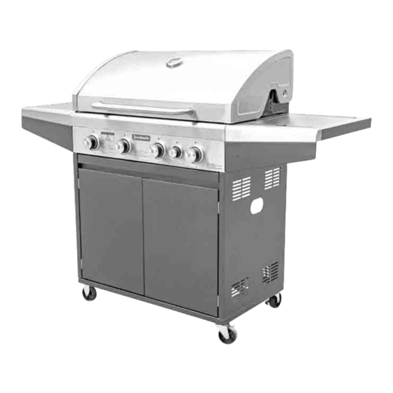
BBQ ASSEMBLY & OPERATION INSTRUCTIONS 4 BURNER WITH SIDE BURNER – MODEL HS-20401 WARNING Important! Please read these instructions carefully before use! FOR OUTDOOR USE ONLY DO NOT OPERATE THIS APPLIANCE BEFORE READING THE INSTRUCTION BOOKLET DO NOT PLACE ARTICLES ON OR AGAINST THIS APPLIANCE DO NOT STORE CHEMICALS OR FLAMMABLE MATERIALS OR SPRAY AEROSOLS NEAR THIS APPLIANCE DO NOT OPERATE THIS APPLIANCE INDOORS... - Page 4 Read these assembly instructions before removing the contents of the carton. MAXIMUM HOOD DOWN SETTING - BURNERS ON LOW DO NOT OPERATE THE BBQ WITH ALL BURNERS ON HIGH AND THE HOOD DOWN.
- Page 5 How to connect and use the new LCC27 LPG Connection* * Fitted to Australia delivered BBQs only. Introduction regulator connection*, recently introduced by the Australian Government. hand wheel. d to an LPG cylinder with the new LCC27 valve, as shown right. ads.
-
Page 6: For Your Safety
FOR YOUR SAFETY FOR YOUR SAFETY 1. Do not store or use gasoline or other If you smell gas: 1. Shut off gas to the appliance at the flammable vapors or liquids in the cylinder. vicinity of this or any other appliance. 2. - Page 7 IMPORTANT This appliance shall only be used in an above ground open-air situation with natural ventilation, without stagnant areas, where gas leakage and products of combustion are rapidly dispersed by wind and natural convection. WARNING A strong gas smell or the hissing sound of gas indicates a serious problem with your BBQ or the LPG gas cylinder.
-
Page 8: Specification
SPECIFICATION REGULATOR & HOSE ASSEMBLY (Supplied with BBQ) : 2.75kPa, LCC27 regulator and 8mm ID, Class A hose with 3/8SAE Female outlet. AGA approved. Burner Configuration Table - Universal LPG BURNERS NOMINAL GAS TEST POINT INJECTOR CONSUMPTION PRESSURE SIZE 11MJ/h (per burner) ULPG @ 2.75kPa 0.92mm Side... - Page 9 Part list...
- Page 10 1. Hood crossbeam - 2. Hood 3. Warming rack 4. Hotplate rear 5. Cooking grill 6. Flame tamer x 2 7. Firebox side panel - 8. Firebox left 9. Hood handle 10. Control knob x 4 11. Side burner knob 12.
- Page 11 17. Grease tray guide - 18. Grease tray guide - 19. Left side front 20. Left side front panel left right panel - upper - lower 21. Cabinet side panel - 22. Cabinet bottom 23. Door hinge x 4 24. Magnet plate Left panel 25.
- Page 12 33. Right side front 34. Right side front 35. Side burner 36. Side burner trivet panel - lower panel - upper 37. Right side table 38. Firebox side panel 39. Firebox rear panel 40. Grease guide plate - right 41. Base weight...
- Page 14 NOTE: Always wear gloves during assembly of this BBQ. Assemble the BBQ on a flat level surface Do not fully tighten the cabinet fasteners until the BBQ is fully assembled, as this will enable straightening / squaring of the assembly at the end. STEP 1 Assemble the ‘Base weight’...
- Page 15 STEP 3 Assemble the ‘Cabinet side panel - Left’ (21) and ‘Cabinet side panel - Right’ (29), ‘Cabinet back panel’ (12) and ‘Magnet plate’ (24) to the ‘Cabinet bottom panel’ using Screw (A) 14pcs as shown. Note: Do not fully tighten the cabinet fasteners until the BBQ is fully assembled, as this will enable straightening / squaring of the assembly at the end.
- Page 16 STEP 5 Assemble the ‘Grease guide plate’ (40) 2pcs on the firebox (8) using screw (E) 4pcs as shown. NOTE: The trays need to be installed on a downward angle towards the center of the BBQ. STEP 6 Assemble the ‘Firebox side panel - left’ (7) and ‘Firebox side panel - right’ (38) to the ‘Firebox’ using Screw (E) 6pcs as shown.
- Page 17 STEP 7 Assemble the ‘Firebox rear panel’ (39) to the ‘Firebox’ using Screw (D) 5pcs and Flange nut (H) 4pcs as shown. NOTE: Do not over tighten the nuts in this step, or you may damage the vitreous enamel coating. STEP 8 Insert ‘Control knob’...
- Page 18 STEP 9 Assemble the ‘Firebox’ to the cabinet using Screw (A) 4pcs as shown. Note: Before mounting remove the regulator hose, ignitor lead and side burner hose from behind the gas knob fascia panel When mounting ensure that the stainless steel hose is located in the cutout in the ‘Separation panel’...
- Page 19 STEP 10 Assemble the ‘Cabinet crossbeam’ (30) on the cabinet by Screw (A) 4pcs as shown. Note: Ensure that the stainless steel hose is located in the cutout between the ‘Cabinet crossbeam’ and the ‘Separation panel’.
- Page 20 STEP 11 Assemble the ‘Door hinge’ (23) 4pcs to the ‘Left door’ (25) and ‘Right door’ (26) using Screw (J) 8pcs as shown. Assemble the ‘Left door’ and ‘Right door’ to the cabinet using Screw (J) 8pcs as shown.
- Page 21 STEP 12 Assemble the ‘Left side front panel - upper (19) to the ‘Left side front panel - lower’ (20) and the ‘Right side front panel - upper’ (34) to the ‘Right side front panel - lower’ (33) using Screw (E) 6pcs as shown. STEP13 Assemble the ‘Side table bracket - A’...
- Page 22 STEP 14 Assemble the side panel front to the ‘Left side table’ and ‘Right side table’ using Screw (A) 6pcs as shown. STEP 15 Assemble the ‘Side burner’ (35) to the ‘Right side table’ (37) using Screw (E) 3pcs and Nut (G) 3pcs as shown.
- Page 23 STEP 16 Assemble the completed ‘Left side table’ and ‘Right side table’ to the firebox using Screw (A) 12pcs as shown, 6pcs per side. NOTE: keyhole slot screws are already mounted in fire box and may need to be backed off for initial fitting of side table.
- Page 24 STEP 17 Assemble the ‘Injector bracket’ to the ‘Right side table’ using Screw (D) 2pcs as shown. Note: Insert the injector into the side burner tube. Finally connect the ignition wire to the bottom of the ‘Side burner’ assembly Note: Locate the SS gas hose so it is not visibly hanging down below the side table.
- Page 25 STEP 18 Assemble the ‘Hood handle’ (9) to the ‘Hood’ (2). Note: The screws (2pcs) are already located in the ‘Hood handle’ Assemble the ‘Hood rear panel’ (1) to the ‘Hood’ (2) using Screw (K) 2pcs and Screw(O) 4pcs as shown.
- Page 26 STEP 19 Assemble the complete hood on the firebox using ‘Hinge Pin’ (L) and ‘R pin’ (M) 2pcs as shown. STEP 20 Insert the ‘Flame tamer’ (6) 2pcs and ‘Side burner trivet” (36) on the firebox and side burner as shown. Note: Flame tamers are to be located under the ‘cooking grill’...
- Page 27 STEP 21 Insert the ‘Warming rack’ (3) ‘Cooking grill’ (5) and ‘Hotplate’ (4) into the firebox as shown. STEP 22 Assemble the ‘Grease tray handle’ (31) to the ‘Grease tray’ (16) using Screw (D) 2pcs and Flange nut (H) 2pcs as shown.
- Page 28 STEP 23 Insert the complete grease tray on the firebox as shown. Fully assembled...
- Page 29 Outdoor Areas BBQ LOCATION - Any enclosure in which the appliance is installed or used shall comply with one of the following: An enclosure with walls on all sides, but at least one permanent opening at ground level and no overhead cover. Within a partial enclosure that includes an overhead cover and no more than two walls.
- Page 30 Both ends open OUTDOOR AREA-EXAMPLE 3 Open sides at least 25% of total wall area 30% or more in total of the remaining wall area is open and unrestricted OUTDOOR AREA-EXAMPLE 4 Open sides at least 25% of total wall area 30% or more in total of the remaining wall area is open and unrestricted...
-
Page 31: Leak Testing
CONNECTION TO LPG CYLINDER LEAK TESTING This should be done the first time you connect up the BBQ, and again each use. Always inspect the hose before each use. Connect the regulator to the LPG cylinder and tighten the connection. Turn the gas on at the cylinder, or make sure gas is available to the BBQ, but do not turn the burners on. - Page 32 CONNECTION TO NATURAL GAS This BBQ has been configured for use with LPG from a gas cylinder. If you want to connect this BBQ to a permanent Natural Gas supply, the following steps must be undertaken. 1/ Contact a licensed plumber or gas fitter and arrange a quote to convert this BBQ to Natural Gas and supply any pipework necessary to bring a natural gas supply line to the BBQ installation area.
-
Page 33: Lighting Procedure
LIGHTING PROCEDURE Lighting the BBQ is easy, but must be done with due care. Make sure the LPG cylinder is filled. Make sure that gas is turned on at the cylinder, or that gas is available to the BBQ. ... - Page 34 CONTROLLING THE FLAMES The knobs have three basic positions. You can achieve any flame height between low and high by rotating the knob between these positions. High High High High Note: ‘Light back’ is a situation where the flame burns inside the burner, towards the front, recognized by a sharp roaring sound coming from the burner.
-
Page 35: After Use
BBQ TIPS Before cooking, coat the hotplate with oil. This will prevent food from sticking. Light the burners and leave on high for about 3~5minutes to warm the BBQ up. Avoid continually turning the meat over. When cooking internal juices rise to the surface of the meat and then settle. -
Page 36: Periodic Cleaning
PERIODIC CLEANING Your BBQ will look better and last longer if you keep it clean. You should check the burners periodically for any sort of blockage. To do this, remove and inspect them. If any of the holes are clogged, gently tap the burner onto a hard surface to remove residue. Use a wire brush to unclog the holes. -
Page 37: Burner Maintenance
BURNER MAINTENANCE To reduce the chance of “ FLASH-BACK’ the procedure below should be followed at least once a month in late summer or early autumn when spiders are most active or when your BBQ has not been used for a period of time. 1. - Page 38 Use an air hose to force air through each burner tube. The forced air should pass debris or obstructions through the burner and out the ports. In addition please also complete the following steps to help prolong burner life. 1. Use a wire brush to clean the entire outer surface of each burner until free of food residue, and dirt 2.
-
Page 39: Care And Maintenance
IMPORTANT This product is for outdoor use only. Do not use indoors. Do not use below ground level. Do not store gas cylinders below ground level. LP gas is heavier than air so if a leak occurs the gas will collect at a low level and could ignite in the presence of a flame or spark. - Page 40 How to care for Stainless Steel and keep your BBQ looking great There is a common misconception that Stainless Steel does not rust, however this is not entirely true. The use of harsh cleaners on stainless steel strip the metal of any oil or protective agents which may prevent corrosion.
-
Page 41: Product Warranty
PRODUCT WARRANTY Thank you for purchasing one of our quality Jumbuck products. Your Jumbuck product is covered against defects for a period of 12 months for parts and labour, repair or replacement. This warranty excludes surface rust and damage caused by abuse or neglect. -
Page 42: Installation Conditions
Purchased from………………………………... Any repair does not extend the warranty period. Location……………………………………….. Any parts other than original Jumbuck parts will void this warranty. Model Name and Number…………………….. INSTALLATION CONDITIONS Date of Manufacture…………………………… All installations must conform to the Receipt number………………………………...
Need help?
Do you have a question about the Stardom II and is the answer not in the manual?
Questions and answers
Can’t see where grease tray guides screw into
The grease tray guides on the Jumbuck Stardom II screw into the cabinet using Screw (J) 4pcs.
This answer is automatically generated